ScienceDirect
Materials Today: Proceedings 19 (2019) 1910–1917 www.materialstoday.com/proceedings
2214-7853 © 2019 Elsevier Ltd. All rights reserved.
Selection and/or Peer-review under responsibility of INTERNATIONAL CONGRESS ON SEMICONDUCTOR MATERIALS AND DEVICES.
ICSMD-2017
Evaluation of Electromagnetic Field Data of a Designed Microstrip
Patch Antenna Structure According to Type of Substrate Materials
and Their Thicknesses
Rabia Top
a,*, Seyfettin Sinan Gültekin
b, Dilek Uzer
baKaramanoglu Mehmetbey University, Department of Electrical and Electronics Engineering, Karaman, Turkey bSelcuk University, Department of Electrical and Electronics Engineering, Konya, Turkey
Abstract
Substrate material used in microstrip antenna structures fully impact the performance of antenna and applications of it. In this work, simulations are carried out for microstrip antenna structure used in biomedical applications. Heart vessel structure used for determining heart diseases is modelled in Ansoft HFSS program. Simulations are implemented with and without occlusion in heart vein. Antenna structure is simulated with different substrate materials and different thicknesses of them. After simulations, various electromagnetic field data are obtained and evaluated for dissimilar substrate materials and thickness of them.
© 2019 Elsevier Ltd. All rights reserved.
Selection and/or Peer-review under responsibility of INTERNATIONAL CONGRESS ON SEMICONDUCTOR MATERIALS AND DEVICES.
Keywords: Substrate material; heart; microstrip antenna; HFSS
1. Introduction
Microstrip patch antenna structure contains two conductive and one dielectric materials. Dielectric material between two conductive layers is very important to design a perfect microstrip antenna. This material is defined as substrate. For substrate, several materials are able to use such as air, Teflon, glass and silicon etc. Conductive layers might be materials like copper and aluminum etc. The one of these layers is defined patch radiating part and the
* Corresponding author. Tel.: +90 332 223 20 42; fax: +90 332 241 0635.
other is defined ground plane. Especially the design and dimensions of patch are important to get desired operating frequency. At the same time, the thickness and permittivity of substrate materials play a vital role to obtain resonance frequency.
In Turkey and in the world, the most of death causes are related to the circulatory system. The biggest rate of these causes is heart failures. In a study executed in 2016 by Turkey Statistical Institution 39.8% of death causes is from the circulatory system and the greatest rate in this percentage is showed to be originated in heart failures [1]. The cardiac occlusion is one of the basic parameter on heart diseases. The detection of cardiovascular obstruction without surgery and without tomography has important developments in the name of humanity. Especially when considering human life, the importance of early diagnosis of cardiovascular occlusion increases.
There are countless studies about biomedical microstrip antennas in the literature. Antennas especially are used as solution-oriented. When it comes to human life, importance of such works quite increases. There are a lot of study that antennas are able to be used as in-body, on-body and off-body. Nowadays the application areas of biomedical antennas particularly contain biosensors used as implantable, wearable or etc. [2-8]. Microstrip antennas are mostly preferred because of its cost, size, lightness, easy design and etc. in biomedical applications [9-11]. Such antennas are especially used in detection of diseases.
The purpose of work is to show that a design of microstrip patch antenna with different substrate materials and their thickness is capable of detection of cardiac occlusion in heart veins. By taking account occlusion situation of heart vein, a design is realized. 5.8 GHz is selected as operating frequency due to Industrial, Scientific and Medical (ISM) frequency band. For design and simulation, eliptic probe-fed microstrip patch antenna is used. Microstrip antennas particularly in in-body applications mostly are used to prefer due to some advantages like their dimensions, cost, ease of use and etc. All materials included human body have different permittivity, conductivity and permeability according to operating frequency. At 5.8 GHz, heart vein and occlusion fat used in model have different electrical properties. These values are obtained from [12]. By looking if there is the presence of modelled occlusion in heart vein or not, simulations are implemented in High Frequency Structural Simulator (HFSS). Cardiac occlusion in heart vein are to dissimilar electromagnetic field values in the presence of different substrate materials. That situation shows a useful study based on detecting the presence of cardiac occlusion. Differences of electric field distribution values are obtained by simulating different substrate materials. Both of them are mostly used to design microstrip patch antenna structures because of some advantages. One of them is FR-4 and the other is RT/Duroid 5880. By changing their thicknesses, different electric field values are got on the situation of with occlusion and without occlusion in heart vein. And comparing all designs, the biggest difference is determined between antenna structures.
2. Substrate Materials
2.1. FR-4
FR-4 is a one of the printed circuit boards using epoxy laminates as substrate. FR-4 is both versatile and well-accepted as a standard material for PCB manufacture. FR-4 functions well as an electrical insulator, and has a good strength-to-weight ratio, and is flame resistant [13]. Table 1 shows the some data of FR-4 datasheet. This material mostly is used for microstrip patch antenna designs because of available easy, cost and etc.
Table 1. FR-4 Datasheet [14]. Dielectric Constant – 1 MHz 4.7 Dissipation Factor – 1 MHz 0.014 Q Resonance – 1 MHz >75 Q Resonance – 50 MHz >95 Arc Resistance 125 s Glass Transition Temperature 135 Deg. C Temperature Index 130 Deg. C
2.2. RT/Duroid 5880
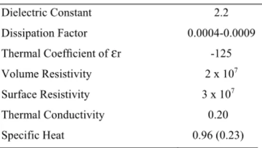
RT/Duroid 5880 high frequency laminates are PTFE (Politetrafloretilen) composites. The dielectric constant of this material is low, and low dielectric loss make it well suited for high frequency/ broad band applications where dispersion and losses need to be minimized. RT/Duroid 5880 laminates are easily cut, sheared and machined to shape, and resistant to all solvents and reagents normally used in etching printed circuits or plating edges and holes. RT/Duroid 5880 laminates have the lowest electrical loss of any reinforced PTFE material, low moisture absorption, are isotropic, and have uniform electrical properties over frequency[15]. Table 2 shows the some data of RT/Duroid 5880 datasheet. This material also usually is used to design microstrip patch antenna designs.
Table 2. RT/Duroid 5880 Datasheet[16]. Dielectric Constant 2.2 Dissipation Factor 0.0004-0.0009 Thermal Coefficient of ɛr -125 Volume Resistivity 2 x 10⁷ Surface Resistivity 3 x 10⁷ Thermal Conductivity 0.20 Specific Heat 0.96 (0.23) 3. Antenna Design
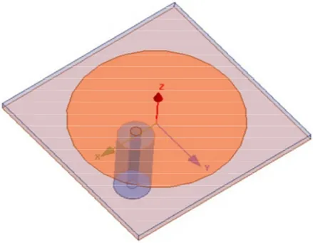
For this work, cylindrical probe fed microstrip patch antenna structure is selected (Fig. 1). Antenna parameters like dimensions are determined according to operating frequency (5.8 GHz) and selected substrate materials. So when each different substrate material and its thicknesses are used, dimensions of the antenna structure changes.
Table 3 shows that the antenna dimensions according to different thicknesses of different substrate materials. For each substrate material, three thicknesses are selected as about equal to each other’s.
Table 3. Antenna dimensions according to different thicknesses of different substrate materials.
Substrate material FR-4 RT/Duroid 5880
Substrate thickness 0.8 mm 1.6 mm 3.2 mm 0.787 mm 1.575 mm 3.175 mm
Substrate dimensions 1.7 cm 2.1 cm 3 cm 2.2 cm 2.7 cm 3.4 cm
Patch dimensions 1.4 cm 1.4 cm 1.25 cm 2 cm 2 cm 1.8 cm
4. Modelled Heart Vein
The permittivity and conductivity of heart vein and fat that used to model the occlusion are 38.2 F/m, 4.3 S/m and 4.95 F/m and 0.29 S/m at 5.8 GHz, respectively[12]. Each of heart vein and its occlusion are modelled as cylindrical structure (Fig. 2). Radius of heart vein is 25 mm and its length is 70 mm. The length of occlusion is the same of heart vein and its radius is 10 mm. Modelled heart structure exactly is placed on patch area of the antenna. Fig. 2 shows the position of heart vein and its occlusion.
5. Simulations and Evaluation
Total twelve simulations are implemented in HFSS program with and without occlusion in heart vein. Three thicknesses of substrate materials are selected to simulate the designs. Electric field data obtained without occlusion are different from electric field values with occlusion. These differences are important to detect if cardiac occlusion is there or not. The maximum electric field values are indicated by a rectangle.
Fig. 1. Proposed microstrip patch antenna design.
Fig. 2. Modelled heart vein.
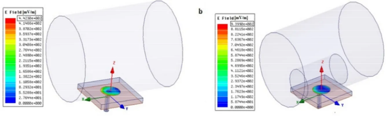
Fig. 3 shows electric field data obtained with and without occlusion for 0.8 mm FR-4 laminate. While there is no occlusion, maximum electric field value is got 3.6 V/m. With occlusion, maximum electric field value is obtained 6.6 V/m. Difference of electric field data is found as 3 V/m. This difference is important to determine whether there is cardiac occlusion or not.
Fig. 4 shows electric field data obtained with and without occlusion for 1.6 mm FR-4 laminate. While there is no occlusion, maximum electric field value is got 1.33 V/m. With occlusion, maximum electric field value is obtained 2.58 V/m.
Fig. 3. Obtained electric field value for 0.8 mm FR-4 laminate (a) without occlusion; (b) with occlusion.
Fig. 4. Obtained electric field value for 1.6 mm FR-4 laminate (a) without occlusion; (b) with occlusion.
Fig. 5 shows electric field data obtained with and without occlusion for 3.2 mm FR-4 laminate. While there is no occlusion, maximum electric field value is got 0.45 V/m. With occlusion, maximum electric field value is obtained 0.94 V/m.
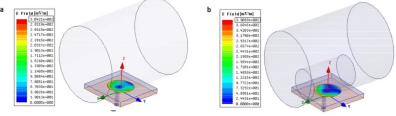
Fig. 6 shows electric field data obtained with and without occlusion for 0.787 mm RT/Duroid 5880 laminate. While there is no occlusion, maximum electric field value is got 2.34 V/m. With occlusion, maximum electric field value is obtained 3.6 V/m.
Fig. 7 shows electric field data obtained with and without occlusion for 1.575 mm RT/Duroid 5880 laminate. While there is no occlusion, maximum electric field value is got 0.83 V/m. With occlusion, maximum electric field value is obtained 1.27 V/m.
Fig. 8 shows electric field data obtained with and without occlusion for 3.175 mm RT/Duroid 5880 laminate. While there is no occlusion, maximum electric field value is got 0.3 V/m. With occlusion, maximum electric field value is obtained 0.39 V/m.
Fig. 5. Obtained electric field value for 3.2 mm FR-4 laminate (a) without occlusion; (b) with occlusion.
There is a chart that is another present of different electric field data according to different thicknesses of different substrate materials (Fig. 9). As seen from chart, electric field values increases in the situation of presence of cardiac occlusion. Also as the thickness of substrate material increases, obtained electric field values are reduced.
Fig. 6. Obtained electric field value for 0.787 mm RT/Duroid 5880 laminate (a) without occlusion; (b) with occlusion.
Fig. 8. Obtained electric field value for 3.175 mm RT/Duroid 5880 laminate (a) without occlusion; (b) with occlusion.
Fig. 9. Another present of different electric field data according to different thicknesses of different substrate materials.
6. Conclusion
Cylindrical probe fed microstrip patch antenna structure is implemented to detect cardiac occlusion. Antenna designs formed with different substrate materials and their different thicknesses are evaluated to determine the best performance inside them. Three thicknesses from two substrate materials are selected and simulations are done according to this situation. Antenna parameters are defined by using operating frequency and dielectric material in the content. 5.8 GHz is selected as operating frequency allowed in biomedical applications between ISM frequency spaces. With obtained primary radiation and reflection data, the efficiency of antenna performance is presented. Proposed antenna, both heart vein and its occlusion are modelled as thinking the occlusion. Because cardiac occlusion is one of the main reasons for the onset of heart conditions and the degree of occlusion plays a vital role, simulations have been done by modelling cardiac vessel occlusion. With the simulation of model, obtained electric field values are evaluated. Each simulation result has a different electric field value. And the different field data are important to determine the presence of cardiac occlusion. As considering the field values according to simulation results, 0.8 mm FR-4 laminate design has the best performance for this work because of the biggest difference that is 3 V/m of obtained electric field values. But 3.175 mm RT/Duroid 5880 laminate design is the worst design for this study. Because the difference of field values with and without occlusion is almost absent.
References
[1] T. İ. Kurumu, "Ölüm nedeni istatistikleri, 2016," in Türkiye İstatistik Kurumu Haber Bülteni vol. 24572, ed, 2017.
[2] J. P. Dieffenderfer et al., "Wearable wireless sensors for chronic respiratory disease monitoring," in Wearable and Implantable Body Sensor
Networks (BSN), 2015 IEEE 12th International Conference on, 2015, pp. 1-6: IEEE.
[3] T. Karacolak, A. Z. Hood, and E. Topsakal, "Design of a dual-band implantable antenna and development of skin mimicking gels for continuous glucose monitoring," IEEE Transactions on Microwave Theory and Techniques, vol. 56, no. 4, pp. 1001-1008, 2008.
[4] S. Vaddiraju, M. Kastellorizios, A. Legassey, D. Burgess, F. Jain, and F. Papadimitrakopoulos, "Needle-implantable, wireless biosensor for continuous glucose monitoring," in Wearable and Implantable Body Sensor Networks (BSN), 2015 IEEE 12th International Conference on, 2015, pp. 1-5: IEEE.
[5] J. Kim and Y. Rahmat-Samii, "Implanted antennas inside a human body: Simulations, designs, and characterizations," IEEE Transactions on
microwave theory and techniques, vol. 52, no. 8, pp. 1934-1943, 2004.
[6] R. Chávez-Santiago, C. Garcia-Pardo, A. Fornes-Leal, A. Vallés-Lluch, I. Balasingham, and N. Cardona, "Ultra wideband propagation for future in-body sensor networks," in Personal, Indoor, and Mobile Radio Communication (PIMRC), 2014 IEEE 25th Annual International
Symposium on, 2014, pp. 2160-2163: IEEE.
[7] A. Alomainy et al., "Statistical analysis and performance evaluation for on-body radio propagation with microstrip patch antennas," IEEE
Transactions on Antennas and Propagation, vol. 55, no. 1, pp. 245-248, 2007.
[8] P. S. Hall and Y. Hao, "Antennas and propagation for body centric communications," in Antennas and Propagation, 2006. EuCAP 2006.
First European Conference on, 2006, pp. 1-7: IEEE.
[9] M. Nalam, N. Rani, and A. Moha, "Biomedical application of microstrip patch antenna," Int J Innov Sci Mod Eng, vol. 2, no. 6, pp. 319-327, 2014.
[10]P. Soontornpipit, C. M. Furse, and Y. C. Chung, "Design of implantable microstrip antenna for communication with medical implants," IEEE
Transactions on Microwave theory and techniques, vol. 52, no. 8, pp. 1944-1951, 2004.
[11]S. Samal, S. Dwari, A. Dutta, and S. P. Reddy, "A Microstrip Patch antenna for biomedical applications at 2.45 GHz," in Computers and
Devices for Communication (CODEC), 2012 5th International Conference on, 2012, pp. 1-4: IEEE.
[12]I. f. A. P. Italian National Research Council. Dielectric Properties of Body Tissues. Available: http://niremf.ifac.cnr.it [13] S. Circuits, "FR-4 PCB Materials."
[14] Farnell. FR-4 Datasheet. Available: https://www.farnell.com/datasheets/1644697.pdf
[15] R. Corporation. RT/duroid 5880 Laminates. Available: http://www.rogerscorp.com/acs/products/32/rt-duroid-5880-laminates.aspx
[16] R. Coorporation. RT/duroid 5880 Datasheet. Available: http://www.rogerscorp.com/documents/606/acs/RT-duroid-5870-5880-Data-Sheet.pdf