IMPROVE CONTROL STRATEGY FOR POWER
SHARING IN ISLANDED MICROGRID
2021
MASTER THESIS
ELECTRICAL & ELECTRONICS
ENGINEERING
AIMEN M. ALSHIREEDAH
THESIS ADVISOR
IMPROVE CONTROL STRATEGY FOR POWER SHARING IN ISLANDED MICROGRID
Aimen M. ALSHIREEDAH
T.C.
Karabuk University Institute of Graduate Programs
Department of Electrical & Electronics Engineering Prepared as
Master Thesis
Thesis Advisor
Assoc. Prof. Dr. Ziyodulla YUSUPOV
KARABUK April 2021
ii
I certify that in my opinion the thesis submitted by Aimen M. ALSHIREEDAH titled “IMPROVE CONTROL STRATEGY FOR POWER SHARING IN ISLANDED MICROGRID” is fully adequate in scope and in quality as a thesis for the degree of Master of Science.
Assoc. Prof. Dr. Ziyodulla YUSUPOV ... Thesis Advisor, Department of Electrical-Electronics Engineering
APPROVAL
This thesis is accepted by the examining committee with a unanimous vote in the Department of Electrical & Electronics Engineering as a Master of Science thesis. April 9, 2021
Examining Committee Members (Institutions) Signature
Chairman : Assist. Prof. Dr. Ozan GÜLBUDAK (KBU) ...
Member : Assoc. Prof. Dr. Ziyodulla YUSUPOV (KBU) ...
Member : Assist. Prof. Dr.Adem DALCALI (BANU) ...
The degree of Master of Science by the thesis submitted is approved by the Administrative Board of the Institute of Graduate Programs, Karabuk University.
Prof. Dr. Hasan SOLMAZ ...
iii
“I declare that all the information within this thesis has been gathered and presented in accordance with academic regulations and ethical principles and I have according to the requirements of these regulations and principles cited all those which do not originate in this work as well.”
iv ABSTRACT
M. Sc. Thesis
IMPROVE CONTROL STRATEGY FOR POWER SHARING IN ISLANDED MICROGRID
Aimen M. ALSHIREEDAH
Karabük University Institute of Graduate Programs
The Department of Electrical and Electronic Engineering
Thesis Advisor:
Assoc. Prof. Dr. Ziyodulla YUSUPOV April 2021, 84 pages
Distributed energy resources are expected to play a vital role to meet the future energy demand response in power system and for the development of Microgrid concept. In the last years, Microgrid as basic part of Smart Grid is being more attractive. It is becoming not only an addition but also an alternative for low and medium distribution network of conventional power systems. Unlike to conventional power systems microgrid operates in two modes, i.e., grid-connected and island modes. Therefore, control strategies of microgrid differs from power systems, too.
The modeling, control design and stability analysis for parallel inverters in the islanded microgrid are considered in this research work. Primary control strategy of microgrid is studied and based on investigations parallel connected inverters technique is proposed to improve microgrid control strategy for island mode operation.
v
The differences in the type of output impedance (inductor/resistor) of parallel inverters can affect the accuracy of power-sharing and thus destabilize the system. The dissertation studies this phenomenon by utilizing the Bode plot technique. The controller based on virtual impedance is proposed to enhance the stability of the system.
This thesis proposes improved method of controlling reactive power-sharing. The results of the simulation are implemented in MATLAB/Simulink to verify the validity of the theoretical analysis, robustness and efficiency of the proposed controllers. The results of proposed method have compared with a conventional method.
Key Words : Microgrid, distributed generation, reactive power sharing, droop control, island mode, virtual impedance.
vi ÖZET Yüksek Lisans Tezi
ADA MİKRO ŞEBEKEDE GÜÇ PAYLAŞIMI İÇİN KONTROL STRATEJİSİNİN GELİŞTİRİLMESİ
Aimen M. ALSHIREEDAH
Karabük Üniversitesi Lisansüstü Eğitim Enstitüsü
Elektrik ve Elektronik Mühendisliği Anabilim Dalı Tez Danışmanı:
Doç. Dr. Ziyodulla YUSUPOV Nisan 2021, 84 sayfa
Gelecekte güç sisteminde enerji talebinin karşılanması ve Mikro Şebeke konseptinin geliştirilmesi için dağıtılmış enerji kaynaklarının hayati bir rol oynaması beklenmektedir. Son yıllarda, Akıllı Şebekenin temel parçası olan Mikro Şebeke daha çekici hale gelmektedir. Geleneksel güç sistemlerinin düşük ve orta dağıtım ağları için sadece bir ek değil, aynı zamanda bir alternatif haline gelmektedir. Geleneksel güç sistemlerinden farklı olarak mikro şebeke iki moda çalışır, yani şebekeye bağlı ve ada modları. Bu nedenle, mikro şebekenin kontrol stratejileri de güç sistemlerinden farklıdır.
Ada mikro şebekedeki paralel eviricilerin modellemesi, kontrol tasarımı ve kararlılık analizi bu araştırma çalışmasında dikkate alınmıştır. Mikro şebekenin birincil kontrol stratejisi incelenmiştir ve araştırmalara dayalı olarak, ada modu işletimi için mikro
vii
şebeke kontrol stratejisini iyileştirmek için paralel bağlı invertörler tekniği önerilmiştir.
Paralel eviricileri çıkış empedansının (indüktör /direnç) tipindeki farklılıklar, güç paylaşımının doğruluğunu etkileyebilir ve böylece sistemi kararsız hale getirebilir. Tezde Bode diagramini kullanarak bu fenomen incelenmiş. Sanal empedansa dayalı bir kontrolör mikro şebeke sisteminin kararlılığını artırmak için önerilmiştir.
Bu tez, reaktif güç paylaşımını kontrol etmek için geliştirilmiş bir yöntem önermektedir. Simülasyonun sonuçları, önerilen kontrolörlerin teorik analizinin, sağlamlığının ve verimliliğinin geçerliliğini doğrulamak için MATLAB/Simulink'te uygulanmış. Önerilen yöntemin sonuçları geleneksel bir yöntemle karşılaştırıldı.
Anahtar Kelimeler : Mikro şebeke, dağıtılmış üretim, reaktif güç paylaşımı, düşüş kontrolü, ada modu, sanal empedans.
viii
ACKNOWLEDGMENT
Firstly, I would like to express my sincere gratitude to my supervisor Assoc. Prof. Dr. Ziyodulla YUSUPOV for his continued support to me to finish my master's degree, thanks for his motivation, enthusiasm, patience, also always his door was open to me for any trouble or question related to my research and he steered me in the right direction for writing my thesis paper .
My sincere thanks also to my parents, children, and my family, and I must express my profound gratitude to my wife for the unfailing support to me throughout my years of study. This fulfillment would not have been possible without them.
ix CONTENTS Page APPROVAL ... ii ABSTRACT ... iv ÖZET... vi ACKNOWLEDGMENT ... viii CONTENTS ... ix
LIST OF FIGURES ... xii
LIST OF TABLES ... xvi
PART 1 ... 1
INTRODUCTION ... 1
1.1. CONCEPT OF MICROGRID ... 1
1.2. THE RESEARCH PROBLEM ... 4
1.3. THESIS OBJECTIVES ... 5
1.4. CONTRIBUTION ... 5
1.5. THESIS ORGANIZING ... 5
PART 2 ... 6
THE ARCHITECTURE AND PROPERTIES OF MICROGRID ... 6
2.1. INTRODUCTION ... 6
2.2. THE ARCHITECTURE OF MICROGRID ... 7
2.3. OPERATION MODES OF THE MICROGRID ... 9
2.3.1. Island Mode ... 9
2.3.2. Connected to Grid ... 9
2.4. THE COMPONENTS OF THE MG ... 10
2.4.1. Distributed Generators ... 10
2.4.2. Storage Systems ... 11
2.4.3. Loads... 12
2.4.4. Control Unit ... 13
x Page 2.5.1. AC Microgrid... 13 2.5.2. DC Microgrid... 14 2.5.3. Hybrid Microgrid ... 15 2.6. CONCLUSION ... 16 PART 3 ... 17
INVERTER BASED MICROGRID CONTROL TECHNIQUES ... 17
3.1. HIERARCHICAL CONTROL OF MICROGRID ... 17
3.2. CONCEPT OF DROOP CONTROL ... 19
3.3. DROOP CONTROL IMPROVEMENTS ... 25
3.3.1. Sharing of the Load ... 25
3.3.1.1. Power-Sharing Dynamic ... 25
3.3.1.2. Power Calculation ... 26
3.3.1.3. The Load Sharing Accuracy ... 26
3.3.2. Regulating Frequency and Voltage ... 27
3.3.3. Virtual Impedance ... 27
3.3.4. Sharing Current Harmonics ... 29
3.3.5. Power-Sharing ... 29
3.4. CONCLUSION ... 33
PART 4 ... 35
THE EFFECT OF VIRTUAL IMPEDANCE ON INVERTER’S CONTROL TOPOLOGIES ... 35
4.1. INTRODUCTION ... 35
4.2. VOLTAGE AND CURRENT CONTROL LOOPS ... 36
4.2.1. Outer Voltage Control Loop ... 36
4.2.2. Inner Current Control Loop ... 37
4.3. SINGLE-LOOP VOLTAGE CONTROLLER ... 38
4.4. DOUBLE-LOOP VOLTAGE CONTROLLER ... 43
4.5. DROOP CONTROL BLOCK DIAGRAM ... 46
4.6. PROPOSING OF THE VIRTUAL IMPEDANCE ... 48
xi
Page
4.8. CONCLUSION ... 55
PART 5 ... 57
IMPROVING ACCURACY REACTIVE POWER SHARING BETWEEN PARALLEL INVERTERS IN ISLANDED MICROGRID ... 57
5.1. INTRODUCTION ... 57
5.2. ANALYSIS OF SMALL-SIGNAL OF SHARING REACTIVE POWER ... 58
5.3. THE PROPOSED CONTROLLER ... 63
5.4. RESULTS OF SIMULATION ... 66 5.5. CONCLUSION ... 73 PART 6 ... 75 6.1. CONCLUSION ... 75 6.2. FUTURE WORK ... 76 REFERENCES ... 77 RESUME ... 84
xii
LIST OF FIGURES
Page
Figure 1.1. Microgrid structure ... 2
Figure 1.2. Inverter structure including 6 IGBT and LCL ... 3
Figure 2.1. An instance of the microgrid ... 7
Figure 2.2. Microgrid architecture ... 8
Figure 2.3. Components of the MG ... 10
Figure 2.4. AC MG with critical and non-critical loads ... 14
Figure 2.5. DC microgrid ... 15
Figure 2.6. Hybrid microgrid ... 16
Figure 3.1. Hierarchical control structure of MG ... 18
Figure 3.2. The Microgrid control structure... 19
Figure 3.3. Schematic diagram of master-slave control. ... 20
Figure 3.4. Control of power flow between two nodes. ... 21
Figure 3.5. The connection two inverters with the load in island-mode. ... 22
Figure 3.6. Relationships Q-V and P-ω ... 23
Figure 3.7. Block diagram of droop controller. ... 24
Figure 3.8. Structuring secondary control. ... 27
Figure 3.9. Block diagram of small-signal injection technique. ... 30
Figure 3.10. Proposed the Q-V dot controller. ... 31
Figure 3.11. Reactive power-sharing by using online voltage drop value. ... 32
Figure 3.12. Proposed robust droop controller against calculation and components mismatch. ... 33
Figure 4.1. General microgrid structure. ... 36
Figure 4.2. Outer voltage control loop. ... 36
Figure 4.3. The inner current control loop. ... 37
Figure 4.4. Voltage and current control loops... 37
Figure 4.5. Control block of each inverter module. ... 38
Figure 4.6. The general structure of the inverter, including the LCL filter. ... 39
xiii
Page
Figure 4.8. The output sinusoidal voltage waveform is divided before filtering. ... 40
Figure 4.9. Sinusoidal output voltage waveform with high-quality... 40
Figure 4.10. The output current waveform. ... 41
Figure 4.11. Minimizing error between signal desired and output voltage measure 41 Figure 4.12. The basic single-loop voltage controller model... 42
Figure 4.13. Bode-plot of the single-loop voltage controller. ... 43
Figure 4.14. The basic double-loop voltage controller model. ... 43
Figure 4.15. Double loop voltage controller's Bode plot. ... 44
Figure 4.16. Output Impedance Bode plot with IL and IC as feedback... 45
Figure 4.17. Droop control block diagram. ... 46
Figure 4.18. Cases of the supposition of output impedance for droop control. ... 47
Figure 4.19. Block diagram of Virtual Impedance with droop control. ... 48
Figure 4.20. Dual-loop voltage controller model including virtual impedance. ... 49
Figure 4.21. Bode plot for output impedance ... 51
Figure 4.22. Single line diagram of parallel inverters of MG. ... 52
Figure 4.23. MG parallel inverters in MATLAB/Simulink. ... 53
Figure 4.24. Active power and current responses. ... 55
Figure 5.1. Structure of microgrid, including converters. ... 58
Figure 5.2. Simple islanded-microgrid consisting of two inverters parallel. ... 59
Figure 5.3. Case of supposition of inductive output impedance for droop control. 60 Figure 5.4. Influence the sharing of reactive power through voltage drop. ... 61
Figure 5.5. Proposed controller scheme: (a) Phase 1; (b) Phase 2. ... 64
Figure 5.6. Scheme of communication for proposed controller... 66
Figure 5.7. Simulation network. ... 67
Figure 5.8. Power-sharing of inverters utilizing conventional droop control for high, medium and low loads. ... 69
xvi
LIST OF TABLES
Page
Table 2.1. Comparison of MG properties with conventional power grid. ... 6
Table 2.2. Typical characteristics for common DG sources ... 11
Table 2.3. Basic storage devices' characteristics ... 12
Table 3.1. Active /reactive power in paralleled inverters ... 22
Table 3.2. Impedance values of the typical lines. ... 25
Table 4.1. Characteristics of Droop controller for active / reactive power. ... 47
Table 4.2. MG system parameters... 52
Table 5.1. Parameter values of the Simulation. ... 68
Table 5.2. Summary of comparing simulation results between the traditional controller and proposed controller for reactive power sharing. ... 73
1 PART 1
INTRODUCTION
1.1. CONCEPT OF MICROGRID
The attention to distributed generation systems (DG) is growing rapidly, as enormous power plants have become less viable due to increased fuel prices, its finite availability and knowledge of the adverse effects of burning fossil fuels on humans and the environment also rigid environmental regulations [1]. Furthermore, the latest technological advances to small generators, energy storage devices and power electronics offered new opportunities related to distributed energy resources in distributed level. There are several disadvantages to the traditional central power generation system. First, power plants rely significantly on fossil fuels, which increases carbon dioxide emissions and wastes heat. Second, a big amount of electricity is generated in one place and transmitted using expensive transmission lines and transformers. Third, these latter because several problems including voltage droop and power loss. Fourth, traditional centralized power generation cannot provide economically appropriate solutions to supply electricity poor and remote communities. Integration of renewable energy (like wind, solar energy) help reduce carbon dioxide emission from energy sources dependent on fossil fuels, reduce losses in transmission, reduce voltage variance, mitigate peak loads and improve supply reliability. On the other hand, excess penetration to DG sources (especially in distribution networks) can cause issues like voltage rising, voltage and frequency instability, and lack of coordination between protection [2,3]. These problems are mitigated by combining multiple DG sources and loads and implementing a controller on them, and this is called a microgrid (MG), as shown in Figure 1.1.
2
Figure 1.1. Microgrid structure [4].
There are several advantages to the MG, such as high reliability, high controllability and high-power quality. MG is a small power system where the generation and distribution of electricity to the consumer execute locally [5].
MG includes DG sources like photovoltaic modules (PV), wind turbine, gas microturbines, and also energy storage systems (battery, flywheel, supercapacitors) to provide power for loads [6]. These DG sources cannot be easily connected with the utility grid in direct current (PV and batteries) or in alternating current with variable frequency (wind turbine/gas microturbines). Electronic power converters therefore necessary to link these DGs with the grid. Network interface inverters are connected to an AC bus in parallel, which will be connected to a utility grid through a static transfer switch. The load is tied to a microgrid side through the static transfer switch (STS). The MG is operating in two modes: grid connecting mode and an island (stand-alone mode). While the MG is in on-grid mode, is able to export or import electricity
3
from the grid, which acts as a manageable source or load. Further, the grid defines MG's apparent power flow to minimize imported electricity from the main grid. In the other mode (island mode), the MG is designed to operate in an isolated mode, when the grid is isolated (STS open) because of emergencies, fault, or natural disasters, all electricity is supplied by power sources that are locally available in the MG [7].
A vital part of any MG is the inverter, which is founded on power electronics consisting of semiconductor components with high-frequency switching and low-pass filter as seen in Figure 1.2. An inverter input is a direct current which is produced via the DC coupling capacitor, whereas the output is alternating current, which is generated at the inverter output. The switching devices, Insulated-gate bipolar transistor (IGBT), that through a voltage regulator, it receives control signals, then generates pulse width modulation signal (PWM) which is associated with a reference voltage. The switching tool's AC output produces several harmonic signals that arise from switching so the LCL filter was used to minimize harmonics and generate the power signal of the sine wave.
Figure 1.2. Inverter structure including 6 IGBT and LCL [8].
The major emphasis of this study is to improve control strategy technics for droop control-based inverters in island position that shape a microgrid. High reliability, stability and robustness should be supported by the control system against the sudden change in load and also the unequal output impedance between DG units due to the difference of cables length among all paralleled inverters), that lead to inaccurate
4
droop control, especially with regard to reactive power-sharing (Q). Frequency and voltage stabilization must be maintained, so the accuracy of power-sharing among all paralleled inverters is important to reach high stability. Inaccuracy power-sharing could get to undesirable circulating power flow. Also since the power-sharing is load-dependent, thus the total power of the parallel inverters have to be more than or equal to the demanded load in order for to stability is achieved [9]. Using traditional droop control, accurate active power-sharing could easily be accomplished since the frequency of the system could be viewed as virtual communication bond among the inverters. Q-sharing in island microgrid, however, rely on output voltages that may differ from point to point relying on interconnecting cables' impedances and the place each inverter. Prior research has shown that the communication bond among inverters and the supervisory controller, through sensing those voltage nodes, has an essential role to maintain precise reactive power-sharing. The lack of this contact, however, could get to instability. Some literature addressed the effect of the difference in the type of output impedances of parallel inverters and revealed that this could generate resonance and make instability. However, the emphasized effect of various feedback signals of the loop of voltage control on the shape of output impedances is not clarified well thus for getting robust controllers against this issue, further work is still required.
1.2. THE RESEARCH PROBLEM
A natural problem for inverters operates in parallel in the islanded microgrid is how to accurately share the load between them. In paralleled inverters, the droop control was invariably the first option. When using this traditional technique against the sudden change in load and also the unequal output impedance between DG units, although real sharing in island MG is usually accurate, it is inaccurate for reactive power-sharing so causes instability [10]. In addition, the different nature of the output impedances of paralleled inverters that relies on different voltage controllers of inverters has shown that these may perform resonance and thus to instability.
5 1.3. THESIS OBJECTIVES
This dissertation is concerned on basic study of techniques for controlling island MG based on droop-control. The dissertation also presents the investigation of equal shared use of reactive / active power among inverters. Moreover, developing a conventional droop control element, demonstrating its strengths and weaknesses, and implementing some feasible solutions such as virtual impedance.
1.4. CONTRIBUTION
The major contribution of this dissertation is designing a controller for a group of connected inverters in parallel in island mode, where the droop control technic is applied to realize power-sharing in the island mode. Adding an improvement to traditional droop control through proposed control makes accuracy reactive power-sharing thus maintaining stability. In addition, Investigations into virtual impedance influence on the stability of inverters connected in parallel. Moreover, the study on the different output impedance natures that affect stability is developed. To improve system stability, voltage controllers with double loops are offered.
1.5. THESIS ORGANIZING
Part 1 presents an introduction to the microgrid. Part 2 introduces the architecture and properties of microgrids. Literature review related to power-sharing techniques; particularly drooping control is presented in Part 3. Part 4 studies the impact virtual impedance on the stability of inverters connected in parallel. Moreover, studies the influence the different nature of the output impedance that relies on different voltage controller of inverters. In Part 5, the inaccuracy of reactive power-sharing is illustrated in island mode, and the controller is proposed to improve system operation. Chapter 6 offers conclusion and future works.
6 PART 2
THE ARCHITECTURE AND PROPERTIES OF MICROGRID
2.1. INTRODUCTION
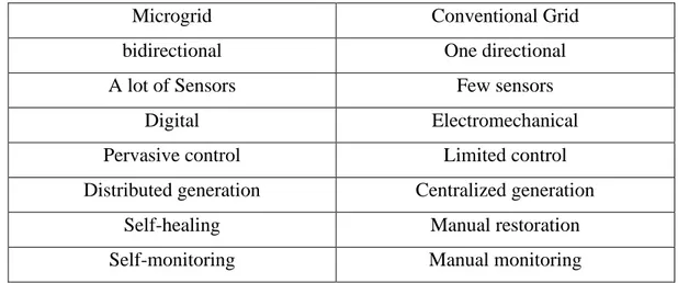
The idiom microgrid (MG) points to the notion of singular subsystems for electrical power that are connected to a number of DERs with a bunch of loads [11]. Renewable energy sources integration help reduce carbon dioxide emission from fossil fuel-based energy sources, reduce transmission losses, reduce voltage variance, mitigate peak loads and improve supply reliability. On the other hand, excess penetration to DG sources (especially in distribution networks) can cause issues like voltage rising, voltage and frequency instability, and lacking coordination between protection. These issues are mitigated by combining multiple DG sources and loads and implementing a controller on them, and this is called a microgrid. In another meaning, the microgrid could be a small power system where creates, distributes, and adjusts the flow of electricity from local DERs to local loads which allows it to connect with the grid or work as stand-alone as shown in Figure 2.1. In the Table 2.1, the properties of MG are compared to the conventional power grid.
Table 2.1. Comparison of MG properties with conventional power grid.
Microgrid Conventional Grid
bidirectional One directional
A lot of Sensors Few sensors
Digital Electromechanical
Pervasive control Limited control
Distributed generation Centralized generation
Self-healing Manual restoration
7
Figure 2.1. An instance of the microgrid [12]. 2.2. THE ARCHITECTURE OF MICROGRID
The fundamental architecture of MG is illustrated in Figure 2.2. This shows that MG systems usually constituted of distributed generation sources, storage systems, distribution systems, communication systems, control and loads. The capacity of MG to connect and disconnect a utility grid a utility grid and work independently and efficiently when needed to support local loads. It is strategically important to design a flexible and suitable architecture of the MG system that functions efficiently in isolated and networked methods [13]. From a grid perspective, the principal feature of MG is it is dealt with as controlled within the electrical system that could act as the single load. From the customer's perspective, MG is advantageous because it can meet their need for electricity and heating locally, deliver uninterrupted electricity and improve electricity quality.
8
9
2.3. OPERATION MODES OF THE MICROGRID
One of the microgrid's characteristics is that it is running in two modes: connected to the grid and an island (stand-alone mode). Moreover, it can go from one run mode to another one smoothly. This section describes the characteristics of the two modes of operation.
2.3.1. Island Mode
During the MG is not connected to the utility grid due to open STS is opened, it indicates that it is in island mode. This mode requires DERs being sent within the MG in a coordinated manner in order that regulates voltage and frequency. Successful operation on the island also requires the power demand management execution to balance the generation load. Island mode has two situations: intentional and unintentional. The intended island is created based on a pre-planned decision and opens STS at a predetermined time. Typically, preventive measures are undertaken to bring the intended transition from connected to unconnected mode as smoothly as possible. However, the unintentional island may occur due to the sudden failure in the grid. In this case, by continuously monitoring the network condition, STS recognizes the exceptional state and separates MG from the grid, ensuring continuity of supply of local loads and protection of distributed generators and energy storage units consequently, it improves MG reliability.
2.3.2. Connected to Grid
Under this mode, the MG is in on-grid mode, is able to export or import electricity from the grid, which acts as a manageable source or load. Further, the grid defines MG's apparent power flow to minimize imported electricity from the grid. In the other mode (island mode), the MG is designed to operate in an isolated mode, when the grid is isolated (STS open) because of emergencies, fault, or natural disasters, all electricity is supplied by power sources that are locally available in the MG.
10 2.4. THE COMPONENTS OF THE MG
Although the complexity of MG, it can determine its basic components namely prime movers, energy storage system (ESS), load, and control unit, resulting in Figure 2.3.
Figure 2.3. Components of the MG [14]. 2.4.1. Distributed Generators
MG contains various kinds of generation resources in their range, enabling them to utilize available resources such as sun, wind, water, biomass, etc., and some other DGs are conventional. Another type of source is utilized in combine heat and power (CHP) systems like microturbines. Table 2.2 displays some of the standard characteristics of generally utilized DG sources. DG can act as current source (CSI) or voltage source inverter (VCI) depending on mode that it operates in. VSI is mainly utilized for energy storage system, while CSI is used for wind turbines or photovoltaic cells, requiring maximum power tracking algorithm [15].
11
Table 2.2. Typical characteristics for common DG sources [11].
Characteristics Solar Wind Microhydro Diesel CHP
Availability Geographical location dependent Geographical location dependent Geographical location dependent Any time Dependent on source Output power DC AC AC AC AC
GHG emission None None None High Dependent
on source Control Uncontrollable Uncontrollable Uncontrollable Control
lable Dependent on source Typical interface Power electronic converter (DC-DC-AC) Power electronic converter (AC-DC-AC) Synchronous or induction generator None Synchrono -us generator Power flow control MPPT&DC link voltage controls (+P,±Q) MPPT, pitch & Torque control (+P,±Q) Controllable (+P,±Q) Control lable (+P,Q) AVR and governor (+P,±Q)
At the MG level, various technologies are ordinarily installed that contribute efficiently to electricity generation when consumers demand an environmentally friendly production system at reasonable prices. Therefore, renewable energy resources (RERs) are seen as the best means for generating electricity to ride local load demands with less comparable transmission costs and losses, involving the environmental influence on electricity generation.
2.4.2. Storage Systems
Energy storage is modern technology and plays a vital role at MG, it is considered to be one important factor for the succeeded operation of MG, where it balances power demand with generation. Therefore, the system with a number of micro-sources that are designed for operation in island mode should provide storage options for insuring the power balance. Storage devices such as batteries, super capacitors, and flywheels are very significant to compensate for disturbances in the power grid and large load changes [16]. In the event of sudden changes in a grid system, these appliances could conduct as voltage sources. Therefore, a grope of batteries with wind turbines, solar
12
PV, biomass and microturbine are generally installed to store energy. Likewise, hydroelectric and fuel cell plants incorporate flywheel and supercapacitor bank techniques to store power within off-peak times. Table 2.3 presents characteristics of energy storage devices.
Table 2.3. Basic storage devices' characteristics [11].
Basic features Battery Flywheel Super capacitor
Continuous power (W/kg) 50-100 200-500 500-2000
Typical backup time 5-30 min 10-30 sec 10-30 sec
Losses at standby Very low Variable High
Environmental impact Medium-high Low Low
Maintenance 1/year 1/5 year None
Charging efficiency (%) 75-95 90 85-95
Current energy price ($/kWh) 150-800 3000-4000 4000-5000
Service life (year) 5 20 ˃10
2.4.3. Loads
Consumers in MG can be classified into several types of loads, they may be industrial or residential. Furthermore, there is another way to distinguish the loads, which is the need for continuity of electricity in terms of the importance of the loads. These loads could be non-critical or critical, such as hospitals and monitoring rooms, so that these services include priority for critical load and thus ensure the continuity power for them, which increases the reliability factor. Another criterion for rating loads is their linearity. In fact, when the impedance of the load changes with the voltage applied to it, it is classified as non-linear such as rectifier and also motor loads, which causes harmonics in the current and causes distortions in the voltage wave.
13 2.4.4. Control Unit
It is necessary to coordinate the interaction amongst all components in the system so MG can meet the limitations, especially when the transfer process between the two modes to achieve stability and power quality. That is the role of the controller. MG is joined to the network via STS, which is controlled via the MG central control unit (MGCC) and can also denote it as a supervisor unit. The control of each DG unit also contains an overlapping control loop, which together offers stability as well as precise control of active power and also reactive power for both modes.
2.5. TYPES OF MICROGRID
MGs are classified based on a common bus and distributed power of MG (DC, AC (line frequency) or a combination of AC-DC – hybrids microgrids).
2.5.1. AC Microgrid
By leveraging the existing infrastructure of the AC network such as transformers, distribution and protections AC type of MG is more effortless to implement and design. Numerous MG projects around the world have developed depend on that concept. A typical AC MG structure is illustrated in Figure 2.4. AC bus is used near PCC that is usually designated as a power interface between MG and the utility grid. MG is able to be connected in both modes, relying on the operation needs [17]. This type of MG offers the possibility of integrating DG into the network in a simple manner without major changes. Moreover, the wide range of protective devices on the markets enables a high ability for fault management. Furthermore, voltage levels can easily be edited with low frequency transformers. However, AC architecture has certain disadvantages, such as the requirement of synchronization by the DGs also the circulation of reactive power which makes some losses into the network [14]. In this project, the focus is on the AC MGs.
14
Figure 2.4. AC MG with critical and non-critical loads [18]. 2.5.2. DC Microgrid
Figure 2.5, illustrates the DC MG structure. In this architecture, the DC MG is connected with the grid at the PCC node by a two-way electronic converter called interlinking converter (IC) that allows power exchange in both directions. Most DERs operated usually with DC or have the intermediate circuit dc-link at their electronic power interface, while the endpoint connection of ESSs is exclusively direct current. Furthermore, many electricity consumer loads are supplied with direct current. Consequently, integrating these devices into DC microgrids via DC-DC converters is considered a good choice in terms of increasing efficiency, because fewer converting stages required and there is no reactive power generation. In addition, no synchronization operation is required for the DGs connection. The cons of this type are the requirement for DC conversion to AC at the connection point to the grid. Another issue is the protection part for the DC MG network.
15
Figure 2.5. DC microgrid [18]. 2.5.3. Hybrid Microgrid
A sample hybrid MG structure is illustrated in Figure 2.6. It consists of DC and AC networks, and they are interconnected through a two-way main two-way AC-DC main converter. This structure enables loads to be installed on the DC feeder together with the loads installed on the AC feeder [19]. Hybrid MG collects the advantages both of DC and AC MG and has an Exclusive network for each kind. The cons of this type are the protection aspect of DC MG poses a problem. In addition, the management of this structure is also more complex Because of hardware control requirements associated with DC and AC MGs [20].
16
Figure 2.6. Hybrid microgrid [18]. 2.6. CONCLUSION
Renewable energy source integration help reduce carbon dioxide emission from fossil fuel-established energy sources, reduce transmission line losses, reduce voltage variance, mitigate peak loads and improve reliability. On the other hand, excess penetration to DG sources (especially in distribution networks) can cause issues like voltage rising, voltage and frequency instability, and lacking coordination between protection. These issues are mitigated by combining multiple DG sources and loads and implementing a controller on them, and this is named a microgrid. In another meaning, the microgrid could be a small power system where creates, distributes and adjusts the flow of electricity from local DERs to local loads which allows it to connect with the grid or work as stand-alone. The microgrid architecture and components are discussed in depth in this chapter. The majority of current systems are AC, but technological advancements will enable hybrid microgrid architectures to emerge.
17 PART 3
INVERTER BASED MICROGRID CONTROL TECHNIQUES
3.1. HIERARCHICAL CONTROL OF MICROGRID
To develop a flexible and reliable microgrid, the control tasks of MG is divided over levels, namely the primary, secondary and tertiary. These levels separate the control features and create the management system to restore frequency & voltage, compensate reactive power, mode transfer, regulate voltage and share power. In Figure 3.1 the overall hierarchical control shape is introduced, along with a concise overview main tasks of every controller's level [21].
1. Primary control. It performs to maintain voltage and stabilizes frequency of microgrid following the islanding procedure. It is also responsible for regulating V and I according to a specific reference.
2. Secondary control. This level control compensates the deviations in frequency and voltage in the MG distribution network. It offers a mechanism for synchronization to logically bind or disconnect the MG on the grid. In secondary control the MG's voltage/frequency values are tested and the nominal values are restored. However, this control reacts more slowly than the level of primary control. The secondary level is classified as centralized & distributed (decentralized) control, which is discussed in [22].
3. Tertiary Control. Tertiary control is highest level of hierarchical control responsible for improving the operation of the MG and interacting with the distribution.
4. Network to provide a reference of reactive & active power for the units. This level controls the flow of energy between the MG and the utility. It is responsible for the importing/exporting power for MG [23].
18
Figure 3.1. Hierarchical control structure of MG [21].
In [21], a PI controller was proposed to carry out secondary, tertiary control after voltage V, current I and frequency ω were sensed on two sides of the STS, then sent over a low-bandwidth communication. With this type of control level, a smooth transition is made to decrease circulation currents flows. Further work is proposed in [4,24,25] for the management of these tasks.
The actuality that MG has several DGs units that can work in the two modes, this poses several problems that can cause challenges, especially when transferring between operation modes. This section reviews the literature to spotlight key challenges for MG development and recent results of related studies. The work focuses on control strategy, especially on island mode, in relation to voltage regulators, power-sharing, modeling, and stability problems.
Figure 3.2 shows single-line MG diagram, which contains PV system, wind turbine (WT) system, and ESS. The inverter has interfaced with the PCC bus via a power converter and wires. Via the STS which could be operated by the MG central controller (MGCC) and can rather be denoted as a supervisor unit, the MG is associated to the grid. It also sends all DGs configurations and V, ω, and power setpoints over communication’s low bandwidth channel. Moreover, it has the option of deciding the mode transfer of the process from connected to the island-mode as well as vice versa. The control loops of each unit are nested, which offer stability and precise control of power in the two-mode. It should be noted here DC sources are supposed to have a reliable, controlled output in all distributed generators that can be ready for use via
19
DC/AC converters. Within this work, the regulation of direct current sources will not be discussed.
Figure 3.2. The Microgrid control structure [10]. 3.2. CONCEPT OF DROOP CONTROL
In island mode, the goal of MG control is to realize precise power sharing while accurately regulation of the voltage amplitude & frequency. To attain the above objectives, two control methods can be followed:
1. Master – slave control [26, 27]. In order to realize precise power sharing, this control system utilizes high-speed communication among inverters by having one inverter play the master role of VCI to control ω and V of the MG, while other inverters work as CCI (Figure 3.3). The main drawback of this method is to utilize a high-speed communication that is expensive and reduces the
20
system's reliability. Since the entire system will fail if the master unit fails. In addition, a transition between both modes does not smooth [4].
2. Wireless methods that rely on droop control [27–29]. The wireless name is displayed because this method does not require communication among the inverters.
Figure 3.3. Schematic diagram of master-slave control.
In our work we are used droop control wireless method. The parallel wireless architecture relies on the inverter's ability for regulating both the output V and ω at the same time sharing the requirements for apparent power. The droop control is a key of wireless technology [30,31] which is commonly used in traditional systems of power generation. The benefit of this method is no external mechanism of communication between each device and the central monitoring controller may still be utilized for surveillance and administrative problems. Furthermore, the simple implementation allows plug-and-play operation, which simply relies on the local voltage and current. Therefore, the ease of system is increasing.
As mentioned above, the droop control in island mode does not require the communication. The strong of droop control emerges when all inverters need to share power with no need to connect with others according to their rating. The power flow
21
supply system between two inductor-separated voltage sources is shown in Figure 3.4. It shows how the P can be regulated through the phase angle between the voltage signals and the Q by adjusting the amplitude difference between these sources. In practice, since a resistance value can influence performance inductive, output impedance cannot be strictly inductive.
Inverter Voltage Grid Voltage
𝑃 =𝑉𝑖𝑛𝑣𝑉𝑔𝛿 𝑋𝐿 𝛿 = ∫(𝜔𝑖𝑛𝑣− 𝜔𝑔)
Inverter Voltage Grid Voltage
𝑄 =𝑉𝑔(𝑉𝑖𝑛𝑣− 𝑉𝑔) 𝑋𝐿
Figure 3.4. Control of power flow between two nodes.
Figure 3.5 shows two parallel inverters that sharing load. Both inverters are jointed to load via the output impedance. Both the reactive & active power exported by each inverter can be done in one of two ways relying on the type of output impedance.
22
Figure 3.5. The connection two inverters with the load in island-mode.
Output impedance may be either mostly resistive or inductive, which determines how an inverter will control with exporting power. If output impedance of inverter was entirely inductive, P produced relies on phase difference (𝜃) between each inverter output voltage V and 𝑉𝑝𝑐𝑐, while Q, it relies on magnitude variance (𝑉-𝑉𝑝𝑐𝑐). The status will reverse if system impedance is entirely resistive (see Table 3.1).
Table 3.1. Active /reactive power in paralleled inverters [32].
System's Impedance Mainly Inductive 𝒁𝒐=𝒋𝑿 Mainly Resistive 𝒁𝒐=𝑹 Active Power 𝑃 ≅𝑉𝑝𝑐𝑐 𝑉 𝜃 𝑍° 𝑃 ≅ 𝑉(𝑉 − 𝑉𝑝𝑐𝑐) 𝑍° Reactive Power 𝑄 ≅𝑉(𝑉 − 𝑉𝑝𝑐𝑐) 𝑍° 𝑄 ≅ −𝑉𝑝𝑐𝑐𝑉 𝜃 𝑍°
The output impedance in its natural shape is the inductive state in 3-phase lines. This also applies to a single-phase line if an additional grid inductor (long feeder of the grid-side inductor)is used [15]. Therefore, P is controlled pursuant to the phase angle, while Q is controlled via voltage difference as indicated above. Figure 3.6 displays the relationships Q-V and P-ω.
23
(I) Frequency droop characteristic. (II) Voltage droop characteristic. Figure 3.6. Relationships Q-V and P-ω
The function of droop control is evident in achieving good power sharing between inverters by regulating the output power in island-mode, while accurately control the power injection into a grid in the connected mode. Hence, the droop control equations for both modes are as follows:
• Island Mode: 𝜔 = 𝜔∗− 𝐾
𝜔𝑃 (3.1)
𝑉 = 𝑉∗− 𝐾
𝑎𝑄 (3.2)
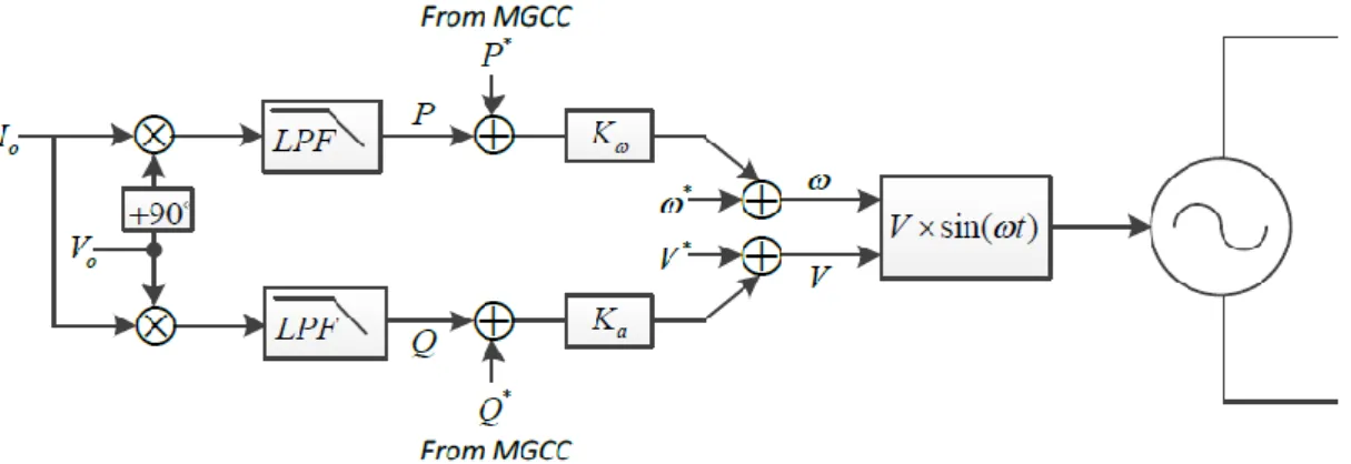
Where: 𝑉∗, 𝜔∗ – voltage & frequency setpoints.
𝐾𝑎, 𝐾𝜔 – Voltage and frequency droop coefficients, respectively. 𝑃, 𝑄 – active power & reactive power.
• Grid-Connected Mode: 𝜔 = 𝜔∗− 𝐾
𝜔(𝑃 − 𝑃∗) (3.3)
24
Where 𝑃∗, 𝑄∗ – the setpoints of exported active / reactive power. These parameters are sent via MGCC, 𝑃 and 𝑄 are measured through a cycle of the essential frequency. This could be done with a low-pass filter by reduced bandwidth [33]. Figure 3.7 displays a droop controller block diagram with measuring filters.
Figure 3.7. Block diagram of droop controller.
While non-communicational way control is the traditional droop form, which lets it further reliable, there are the following drawbacks that restrict its applications [21,34]:
• By utilizing the drooping curve of Figure 3.6 it is illustrated by adjusting the drooping slope to share the reactive force. If we increase it, it will improve the reactive energy sharing but will negatively affect the voltage regulation. Vice versa, there is often trade off since it presents ω and V deviations that are proportional to the Q and P output power.
• Although the dynamics of sharing of power depends on the coefficients of droop control, it also depends on the way of calculating the power as there are low pass filters which lead to additional limits.
• Prior switching back to grid-connected mode, frequency & voltage drop caused by droop control requires a restoration process that reduces seamless transfer mode.
• The droop control uses a purely inductive or purely resistant output impedance assumption, that one in practice is not much precise. Output impedance may be a mixture of the two. This will weaken the decoupling of control loops between reactive & active power since each pure type of output impedance
25
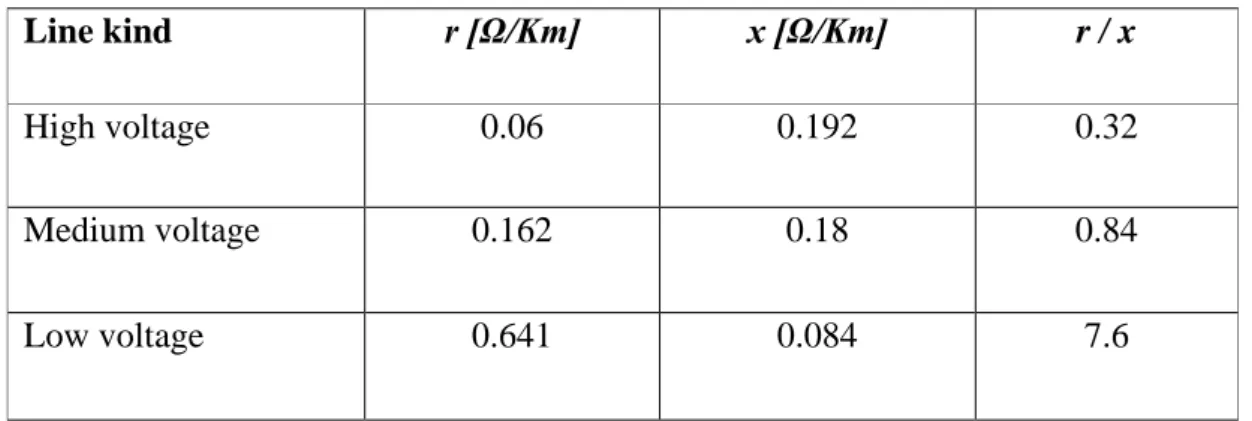
provides a different form of drop control equation, this is also related to distribution network kind (Table 3.2) [35].
• The conventional droop is non-effective if the units provide non-linear load since it is no supportive sharing of harmonic signals.
Table 3.2. Impedance values of the typical lines.
Line kind r [Ω/Km] x [Ω/Km] r / x
High voltage 0.06 0.192 0.32
Medium voltage 0.162 0.18 0.84
Low voltage 0.641 0.084 7.6
3.3. DROOP CONTROL IMPROVEMENTS
Many researchers have been motivated by the significance and value of droop control in MG to work on improving droop control and implementing various solutions to issues caused via their limitations. Some issues on improving droop regulation are considered in this research.
3.3.1. Sharing of the Load
The load sharing in droop control is classified into the following: • Power-sharing dynamic
• Power calculation
• The load sharing accuracy 3.3.1.1. Power-Sharing Dynamic
Solutions have been suggested in various publications [36–38] to improve active & reactive power-sharing transient response in island and grid-connected modes. A unit PID controller was suggested by Guerrero et al. [33] as an alternative on a simple
26
proportional controller in order to enhance dynamic response. Similarly, in order to dampen the transient peak and reduce the circulation currents among inverters, Avelar et al. [39] suggested additional phase loop.
3.3.1.2. Power Calculation
In several studies [39–41], the low-pass filter is also used. Its delayed response, however, affects totality transient of circulation currents and the sharing of power, especially in island-mode. In [4,42] substitute methods were proposed which contain better dynamics, a fast reaction, and less ripple. Moreover, the comparison of many methods is also investigated in [43].
3.3.1.3. The Load Sharing Accuracy
The good accuracy of the power control in the grid connected-mode is achieved thanks to the benefit of the PI controller [4], which removes active & reactive power's steady-state errors. Conversely, in the island's microgrid, this is not easy to execute. The complexity arises from the trade-off between load sharing accuracy and regulation of voltage/frequency. Increasing the gains in droop coefficient to get more precise sharing could degrade control and destabilize a system. A droop control and pair of droop coefficients have proposed to maintain island mode stability at high and low loads in [44]. The new droop controller have been introduced in [45] that makes the droop ratio both P-ω and Q-V non-linear to minimize the drops in voltage and frequency during large load delivery. Moreover, [46] proposed the adaptive droop behavior against large and small loads of steps. Although the high gains needed for better load sharing, an additional loop [38] has suggested to achieve the system's stability. Regulation of the decoupling of virtual (P) and (Q) power by transforming the frame was proposed in [47]. Some researchers have introduced other proposals like [48] that used the generalized integrator of second-order to value the impedance of the grid to replace it in droop control also robust decoupling between (P) and (Q ).
27 3.3.2. Regulating Frequency and Voltage
PCC's voltage & frequency mismatch the MG setpoints in island-mode. Therefore, restoration and regulatory processes are required when the MG reconnects with the grid. In [29,47], the secondary loop was suggested using a PI controller for restoring the needed precise values. The secondary control level is utilized to compensate both frequency & voltage deviations that are caused by primary control in the MG. This control serves to keep the frequency deviations and voltage deviations near-zero or at specified boundaries. However, this control reacts more slowly than the level of primary control [49]. The secondary level is classified as centralized & distributed (decentralized) control, is discussed in [22]. The secondary control' classify ways is clarified in Figure 3.8. The phase drop control was used in [48,49], which lets the frequency is independently on load to be set over time. Furthermore, the authors of [50] enable the operator, via adding an integral gain to real power controller, to tune its controller without affecting frequency control.
Figure 3.8. Structuring secondary control. 3.3.3. Virtual Impedance
The output impedance considers very essentially for good droop control. As mentioned above, when it is no certainty of being purely resistive or inductive or in between, however, it has a negative effect on the decoupling of the P and Q.
28
The purpose of using virtual impedance technique is to solve the power coupling problem owing to the high ratio of R/X in low voltage network [4,50]. This is done by increasing the resistance /inductive of the inverter output impedance without the need to use additional physical resistors/inductors, which adding these physical quantities increases the cost and size. Therefore, the impact of line impedances and network on droop control is reduced. Literature shows recent research to develop a concept of virtual impedance. In [51] a parallel linked virtual resistance impedance control technique is suggested to sharing the current in island-mode. It offers the benefits of a damped system with regard to automatic harmonic sharing and resonance. Inductive virtual impedance is utilized in [33]. A problem for the virtual inductance control scheme, however, is the calculation of the inductor voltage drop that includes differentiation of the line's current. Differentiation could cause high frequency noise amplification, which leads to destabilizing the control scheme of inverter voltage, particularly during the transient. Moreover, virtual impedance reduces the impact of the circulating current between inverters as it supports the soft start process so that it maintains a big impedance in the start and later reduces it to the nominal value in a stable condition [32].
Owing to high load requirements, the inverters should work in parallel, this offers the system redundancy besides the high reliability needed for a flexible MG structure. The powerful design of every inverter so that it can operate in parallel together without disturbances in the system is a parallel inverters' major concern. In general, droop control is executed for the wireless sharing of power among the inverters. However, the different output impedance affects the stability and accuracy of power-sharing. The literature suggests numerous control strategies to address such challenges [4,52–55] However, the emphasized effect of various feedback signals of the loop of voltage control on the shape of output impedances is not clarified well. In this thesis, the voltage controllers for single and double loops and their effect on stability will be studied. In addition, System behavior will analyze by utilizing the Bode plot technique when the capacitor and inductance currents are used as feedback. Furthermore, the differing output impedances of parallel-connected inverters impair stability. A virtual impedance has therefore proposed for stabilizing system and unifying the nature of output impedances.
29 3.3.4. Sharing Current Harmonics
In particular, when providing nonlinear loads in island mode, a method was proposed to deal with nonlinear load-sharing as in [32] by adjustment output voltage bandwidth with supplied harmonic power utilizing the band-pass filter bank, after that, harmonic components of the current signal are extracted and then is re-injected them again in the network. In certain applications, like the UPS system [56], the ohmic output impedance could be a positive for sharing linear and non-linear loads. In [57] a rapid control loop is used, which adjusts the inverters output impedance of in the closed control loop to ensure resistance behavior and to correctly share the harmonic current. In natural output impedance, the impedance of inductive output tends to be more common [32]. In [58], The complex output impedance was shown in which a different design was proposed for a virtual output impedance consisting of a virtual resistor with an HPF-connected virtual inductor. After all, at a nominal frequency, it behaves like an inductor and reflects resistance activity at harmonic frequencies.
3.3.5. Power-Sharing
One of the main concerns of inverters working in parallel is the issue of load sharing. Many techniques used methods based on communication [59–62] to achieve precise load sharing, but those methods require high communication infrastructure bandwidth among all inverters that raises costs and reduces reliability, in addition absence plug-and-play capability. The droop control technique that simulates same synchronous generators behavior [39], introduced the solution so that the inverters work in parallel with no communication mechanism. Accurate active power-sharing could be easily realized utilizing conventional droop control due to parallel inverters are synchronous and have a constant output frequency. On the other hand, to be able the droop controller sharing the reactive power precisely, inverters working in parallel must contain similarly output impedance involving cable impedance and generate similarly output voltage. Even so, in practice, because of the tolerance of parameters in the LC output filter of the inverter, the different lengths of the connection cables, and the inaccuracy of the output voltage control, this cannot be assured. For that reason, conventional drop
30
control has known for its weak Q-sharing performance. Therefore, emphasis will be placed on the reactive power-sharing problem.
A lot of strategies are proposed for improving Q-sharing. An algorithm which is dependent on the injection of an additional control signal has suggested in [63]. The suggested method injects signals at various frequencies (90 Hz, 130 Hz) to transmit information over the same distribution lines about the power shared between the inverters, but this would increase the complication of the control method (Figure 3.10). .
(a)
(b)
31
Chia et al. [64] suggested a technique for compensation of mismatch of lines' impedances, wherein the Q is regulated into proportion with derivative of voltage. Despite minimizing errors in Q-sharing, this method did not realize an even sharing and increases the complication of the system (Figure 3.11).
Figure 3.10. Proposed the Q-V dot controller.
A centralized controller to compensate voltage drop using droop control is suggested in [65]. The entire process, however, is performed in MGCC, and a communication link is used to send all parameters. Losing this communication would result in conventional droop control constraints.
Li et al. [66] suggested an online voltage drop value which happened because of the transmission lines until that improve the gain of the droop control to achieve a precise
Q-sharing in island-mode but the method requires that inverters first work in on-grid
mode to get an appropriate estimate for calculating the new droop gain. Furthermore, the complexity of the controller increases as there are local loads that impact the estimation processes. (Figure 3.12).
32
Figure 3.11. Reactive power-sharing by using online voltage drop value. Zhong (2013) proposes another control system which is strong against errors in calculation and mismatching of components. The control's accuracy does not rely on the impedance of the output. Via a cable link, it continuously tests the load voltage and calculates the variance between this measurement and locally output voltage. In order to obtain an exact sharing of the Q-power, this variance is the input to integrated control system, but this method only acts precisely for inverters and local loads near each other. A wireless connection could be used among the inverters for a remote load point or long distances and any interruption of the communication bond, until for a short time, could cause instability owing to the presence of an integrated controller. In addition, the cable impedances which lead to inaccuracy sharing when the localized output voltage returns are not considered by the controller (Figure 3.13).
33
Figure 3.12. Proposed robust droop controller against calculation errors and components mismatch.
Jincwei et al. [68] suggested the synchronized technique that correctly instructs all units for Q-sharing by using the Q measured in the equation of frequency. This purposely disturbs, however, the precision of P-sharing. Furthermore, the sharing accuracy deteriorates for each load fluctuation after compensation, and therefore the technique must be performed again.
The same authors suggested an online evaluation technique for line impedance in [69, 70] , utilizing PCC voltage and line current harmonics to control the virtual impedance and improve the accuracy of Q-sharing. Even so, both the complexity of the controller and the reliance on harmonic calculations that presume the presence of nonlinear loads during estimation time are increasing.
3.4. CONCLUSION
In this chapter, the latest technologies for the interfacing between renewable energy and technologies of microgrid control in island mode have overviewed. Several techniques adopted communications-based methods to realize good power sharing
34
among parallel inverters but losing this link could be very harmful to the controller performance. The literature review exposed that the droop control technique is a popular method of power-sharing recently without depending on communication link among parallel inverters in island mode. However, it has many deficiencies and is being improved by researches work. It also showed that unifying the type of output impedance among parallel inverters considers very essential for supporting droop control. When it is no certainty of being purely resistive or inductive or in between, however, it has a negative effect on the decoupling of the P and Q power so this can affect the accuracy of power-sharing and thus destabilize. In this thesis, a virtual impedance is therefore proposed to reach the system stability and power-sharing.
35 PART 4
THE EFFECT OF VIRTUAL IMPEDANCE ON INVERTER’S CONTROL TOPOLOGIES
4.1. INTRODUCTION
When making a design for the microgrid control system, it is necessary to achieve stability for each unit in addition to the stability for the entire MG in various conditions of load and system. MG uses inverters to create a connection between distributed generation units (DG) and loads/grid [71,73]. In practical, owing to high load requirements, the inverters should work in parallel, as illustrated in Figure 4.1. This offers the system redundancy besides the high reliability needed for a flexible MG structure. A major challenge of parallel inverters is the robust design of each inverter so that it can operate in parallel together without disturbances in the system. In general, droop control is executed for sharing power wirelessly among the inverters. Nonetheless, unequal output impedance between DG units (due to the difference of cables length among all paralleled inverters) affects the stability and accuracy of power-sharing. The literature suggests numerous control strategies to address such challenges [4,52–55]. However, the emphasized effect of various feedback signals of the loop of voltage control on the shape of output impedances is not clarified well. In this chapter, the voltage controllers for single and double loops and their effect on stability are studied. System behavior is analyzed by using the Bode plot technique when the capacitor and inductor currents are utilized as feedback. Furthermore, differences in the type of output impedance (inductor/resistor) of parallel inverters can affect the accuracy of power-sharing and thus destabilize the system. A virtual impedance has proposed to reach the system stability by unifying the nature of output impedance. Simulation's results are introduced for showing control strategy validity.
36
Figure 4.1. General microgrid structure. 4.2. VOLTAGE AND CURRENT CONTROL LOOPS
4.2.1. Outer Voltage Control Loop
Figure 4.2 reveals the proportional controller-based outer voltage controller loop utilized to compensate error signal of voltage Verror between reference voltage signal
and output voltage signal of inverter for regulation and optimal stability. The voltage-compensated error signal is considered the reference current control Iref for the current control loop.
37 4.2.2. Inner Current Control Loop
Figure 4.3 reveals the internal current control loop based on the PI controller. Reference current Iref is compared with output current Io to produce an error current
Ierror signal which assigned with a PI controller producing PWM signal for full-bridge inverter driving. The benefit of designing an inner loop is having a short settling time and fast harmonic tracking.
Figure 4.3. The inner current control loop.
Slower than the current internal loop is the outer voltage loop. The structure of the double control loop is revealed in Figure 4.4.
Figure 4.4. Voltage and current control loops
The controller must produce a similar voltage setpoint for the inverters using the frequency and voltage droop’s characteristics, with the assumption all inverters connected in parallel have the same output impedance so that they can do load Sharing exactly in proportion with their nominal powers. Figure 4.5 reveals the control block of each inverter module.
38
Figure 4.5. Control block of each inverter module. 4.3. SINGLE-LOOP VOLTAGE CONTROLLER
As mentioned above, the inverter is the linkage between the power sources and loads. Figure 4.6 depicted the general configuration of the inverter with IGBT switches that get modulated sinusoidal wave signals (MSWS) from the unit of voltage controller. The pulse width modulation (PWM) method is common in getting a correct sine wave signal (Figure 4.7). The signal duty cycle produced could somehow be modulated so that the average voltage signal complies with a pure sinusoidal wave utilized in switching control. With sine signal fundamental frequency, this generates high-frequency harmonics (Figure 4.8).
39
Figure 4.6. The general structure of the inverter, including the LCL filter.
Figure 4.7. SPWM Signal. 0 0.001 0.002 0.003 0.004 0.005 0.006 0.007 0.008 0.009 0.01 0 0.1 0.2 0.3 0.4 0.5 0.6 0.7 0.8 0.9 1 PWM SIGNAL
40
Figure 4.8. The output sinusoidal voltage waveform is divided before filtering. LCL filter is utilized to dampen harmonics produced and provide the load with a high-quality signal with low harmonic power (Figure 4.9).
Figure 4.9. Sinusoidal output voltage waveform with high-quality (using LC Filter).
Also, the output current waveform is similar to that of the sinusoidal voltage waveform (see Figure 4.10). 0 0.001 0.002 0.003 0.004 0.005 0.006 0.007 0.008 0.009 0.01 -500 -400 -300 -200 -100 0 100 200 300 400 500 Time, sec V o lt a g e , v
Output voltage wave without (befor) LC filter
0 0.02 0.04 0.06 0.08 0.1 0.12 0.14 0.16 0.18 0.2 -400 -300 -200 -100 0 100 200 300 400 Time, sec V o lt a g e , V
41
Figure 4.10. The output current waveform.
A voltage control loops are utilized in VSI for tracking the input signal desired and also to decrease error between the previous signal desired and output voltage measured as revealed in Figure 4.11.
Figure 4.11. Minimizing the error between the signal desired and output voltage measured.
The proportional controller; 𝑘𝑣; is used in this chapter, propped by the feedforward loop. This loop reduces steady-state errors plus enables a larger bandwidth control. Figure 4.12 displays the LCL filter (physical system) model and the loop for voltage controller. On filter capacitor's terminals, voltage feedback is measured and then
0 0.02 0.04 0.06 0.08 0.1 0.12 0.14 0.16 0.18 0.2 -8 -6 -4 -2 0 2 4 6 8 Time, sec C u rr e n t, A
Sinusoidal output current
0 0.02 0.04 0.06 0.08 0.1 0.12 0.14 0.16 0.18 0.2 -500 -400 -300 -200 -100 0 100 200 300 400 500 Time, (sec) V o lt a g e , (V )
desired input signal measured output voltage
![Figure 2.2. Microgrid architecture [11].](https://thumb-eu.123doks.com/thumbv2/9libnet/5409177.102309/23.892.206.747.145.988/figure-microgrid-architecture.webp)
![Figure 2.3. Components of the MG [14].](https://thumb-eu.123doks.com/thumbv2/9libnet/5409177.102309/25.892.173.783.293.624/figure-components-mg.webp)
![Table 2.2. Typical characteristics for common DG sources [11].](https://thumb-eu.123doks.com/thumbv2/9libnet/5409177.102309/26.892.173.798.170.591/table-typical-characteristics-common-dg-sources.webp)
![Table 2.3. Basic storage devices' characteristics [11].](https://thumb-eu.123doks.com/thumbv2/9libnet/5409177.102309/27.892.163.794.313.697/table-basic-storage-devices-characteristics.webp)