• Sonuç bulunamadı

Implementation of IEEE 802.15.4a Based UWB Systems for Coexistence with Primary Users

N/A
N/A
Protected

Academic year: 2021

Share "Implementation of IEEE 802.15.4a Based UWB Systems for Coexistence with Primary Users"

Copied!
9
0
0

Yükleniyor.... (view fulltext now)

Tam metin

(1)

Implementation of IEEE 802.15.4a Based UWB

Systems for Coexistence with Primary Users

C

¸ a ˘glar Fındıklı, Serhat Erk ¨uc¸¨uk, Mehmet Ertu ˘grul C

¸ elebi

Abstract—Peaceful coexistence is a major implementation issue

for both cognitive radios and ultra wideband (UWB) systems. Accordingly, the UWB impulse radio (UWB-IR) based Wireless Personal Area Network (WPAN) standard IEEE 802.15.4a has suggested using linear combination of pulse to limit interfer-ence to coexisting primary systems. In this paper, motivated by implementing the IEEE 802.15.4a based UWB-IR systems for peaceful coexistence, we consider the implementation of linear combination of pulses as suggested by the standard. Accordingly, we (i) design possible linearly combined pulses that conform to the standard requirements, (ii) consider coherent and noncoherent receiver structures that can be adapted for the physical layer of the IEEE 802.15.4a standard, (iii) investigate the effect of channel models on the system performance, and (iv) study the UWB-IR system performance in the presence of narrowband and orthogonal frequency division multiplexing (OFDM) based wideband primary systems with various band-widths and subcarriers. The study shows that the UWB-IR system performance can be significantly improved by selecting suitable pulses for transmission and employing appropriate filtering techniques at the receiver when the primary system is active. For the implementation of IEEE 802.15.4a based UWB systems complying with coexistence requirements, the results of this study should be carefully considered.

Keywords—Ultra wideband (UWB) systems, cognitive radios,

coexistence, spectrum shaping, pulse design.

I. INTRODUCTION

Cognitive radios [1] and ultra wideband (UWB) systems [2] have emerged as alternative technologies for efficient utilization of the spectrum. Both technologies are referred to as secondary systems, where they have to coexist with licensed (i.e., primary) systems without causing interference to them. While cognitive radios have to assess the availability of the spectrum by means of spectrum sensing [3]–[5] and use the frequency band only if the primary user is not active, UWB systems have to transmit with a low power spectral density (PSD) [6] to limit the interference level to coexisting primary systems. Despite UWB systems being perceived as underlay systems below noise spectrum level, many regulatory agencies worldwide have been cautious and have mandated detect-and-avoid (DAA) techniques in some bands to limit the interference level [7]. In the implementation of DAA, the C¸ . Fındıklı and M. E. C¸ elebi are with the Department of Electronics and Communications Engineering, Istanbul Technical University, Maslak, Istanbul, 34469 Turkey.

S. Erk¨uc¸¨uk is with the Department of Electrical and Electronics En-gineering, Kadir Has University, Fatih, Istanbul, 34083 Turkey. E-mail: serkucuk@khas.edu.tr.

Manuscript received November 13, 2015; revised March 18, 2016; accepted March 21, 2016. This paper was presented in part at the 37th International Conference on Telecommunications and Signal Processing, Berlin, Germany, July 2014.

UWB system initially has to perform spectrum sensing to determine whether the coexisting primary systems are active or not [8], [9]. As the next step, the UWB system either has to keep silent or lower its PSD level at the frequency band of the primary system for avoidance.

Due to the ultra-wide bandwidth nature (at least 500 MHz) of UWB systems, there may be multiple primary systems overlapping with the frequency band of a UWB system. On the other hand, one or more coexisting primary systems may be frequently active. Hence, keeping silent after the detection of one or more primary systems may cause limited operation capability for UWB systems. Alternatively, spectrum shaping and pulse design techniques have been widely considered in the literature. By utilizing the desired spectrum mask and re-ducing the PSD level at the desired frequency band, new pulses have been designed [10]–[12]. The common characteristic of these pulses is that the available spectrum is optimized with no restriction on the number of filter coefficients. However, UWB based systems are commonly accepted as low-cost systems with simple transceiver structures. Accordingly, the UWB im-pulse radio (UWB-IR) based Wireless Personal Area Network (WPAN) standard IEEE 802.15.4a [13] has suggested using linear combination of a few pulses, which is equivalent to using a few filter coefficients, for spectrum shaping purposes. That is, in the presence of an active primary system, the transceiver should generate a new pulse shape based on the aggregation of time-shifted and scaled versions of the original pulse. In [14], the authors have addressed generating pulses with notches at the desired frequencies by conforming to the restrictions in the standard based on a z-transform approach. However, the performance of the designed pulses has not been studied in the presence of an active primary system neither in [14] nor in optimum pulse design studies [10]–[12].

Parallel to pulse design techniques, the effects of narrow-band and widenarrow-band licensed systems (also referred to as “interference” from the UWB communications perspective) on the UWB system performance have been studied [15]– [19]. In [15], jam resistance of UWB systems has been investigated for interferences with various bandwidths. In [16], the effects of GSM900, UMTS and GPS systems on the UWB system performance (and vice versa) have been studied. The authors have evaluated the performance of UWB systems employing differential-Rake (D-Rake) receivers in the presence of narrowband interference in [17]. In [18], an exact analysis has been derived for precisely calculating the bit error probability of a UWB-IR communication system coexisting with an IEEE 802.11a system. In [19], the performance of a

(2)

Multiband Orthogonal Frequency-Division Multiplexing (MB-OFDM) based UWB system has been analyzed in the presence of an IEEE 802.16 WiMAX system. The common approach in these studies is that the UWB systems employ pulses that do not take into account the interference level caused by UWB systems to the licensed systems. However, as mandated by the European and Japanese regulatory agencies, the UWB systems should transmit pulses with reduced power levels at the frequency bands occupied by licensed systems.

Motivated by implementing the IEEE 802.15.4a based UWB-IR systems for peaceful coexistence, we consider the implementation of linear combination of pulses as suggested by the standard. In [20], we have considered the presence of a narrowband interference and used only one type linearly combined pulse to assess the UWB-IR system performance. In this comprehensive study, we consider both narrowband and wideband primary users and employ all possible linearly combined pulses to determine which type of pulse may be preferred for implementation. Accordingly, we can summarize the contribution of the current study as follows. We:

(i) design possible linearly combined pulses that conform to the standard requirements,

(ii) consider coherent and noncoherent receiver structures that can be adapted for the physical layer of the IEEE 802.15.4a standard,

(iii) investigate the effect of channel models on the system performance, and

(iv) study the UWB-IR system performance in the presence of narrowband and OFDM based wideband primary systems with various bandwidths and subcarriers.

For the UWB-IR system performance, many practical sce-narios such as the effects of transmitter-receiver structures, interference level, interference types, pulse types and the IEEE 802.15.4a channel models are investigated in detail. The results of this study are important as they demonstrate an alternative implementation of the IEEE 802.15.4a system complying with the regulatory agency mandates for coexistence, and yet achieving a reasonable system performance.

The rest of the paper is organized as follows. In Section II, IEEE 802.15.4a system model and the associated receiver structures are presented. In Section III, a modified transceiver structure that employs linear combination of pulses for co-existence is presented. In Section IV, simulation results are presented in order to assess the UWB system performance in the presence of narrowband and wideband interferences for various practical scenarios. Concluding remarks are given in Section V.

II. IEEE 802.15.4ASYSTEMMODEL

In this section, the system model of the IEEE 802.15.4a based UWB impulse radios [13] is presented that can support both coherent and noncoherent data reception as given in [20]. The IEEE 802.15.4a standard uses combined binary phase shift keying (BPSK) / binary pulse position modulation (BPPM) for data transmission. While both the phase and position information can be detected by coherent detection, only the position information can be detected by noncoherent detection.

The system model that supports both coherent and noncoherent data reception is explained as follows.

For reliable communications in a dense multipath environ-ment, data transmission is achieved by burst of pulses, where each of theNbconsecutive pulses are transmitted within a chip

timeTcandTb = NbTcis the burst duration. The symbol time

Ts= NcTc, whereNc is the number of chips in a symbol, is

much greater than the burst duration Tb (Ts>> Tb) in order

to allow time hopping (TH) for multiple access (MA) and accommodate guard times to prevent intra- and inter-symbol interferences. With this symbol structure, the lth symbol of

the 1st user that carries the position and phase information

can be transmitted using the signal model w(1)l (t) = Nb−1 X j=0 a(1)l s(1)j pt − lTs−jTc− d(1)l δp− c(1)l Tb  (1)

wherew(1)l (t) is the waveform of the 1st user’slth

transmit-ted symbol consisting of Nb consecutive pulses, p(t) is the

transmitted pulse with duration Tp ≤ Tc, and s (1)

j ∈ {±1}

{j = 0, 1, . . . , Nb− 1} is a scrambling sequence specific to

user-1 that is used to smooth the spectrum. a(1)l ∈ {±1} is the user phase information and can only be seen by the coherent receiver, whereas d(1)l ∈ {0, 1} carries the user position information that can be seen by both coherent and noncoherent receivers, where δp = Ts/2 is the position

shift parameter. Accordingly, this combined modulation is regarded as BPSK/BPPM.{c(1)l } are the TH integer values that scramble the position of the burst for multiuser interference suppression. The condition cmaxTb + Td ≤ δp should be

satisfied in order to prevent inter-symbol interference, where cmax is the maximum TH shift integer value and Td is the

maximum channel delay spread.

In order to prevent inter-pulse interference and to specifi-cally evaluate the effect of linear combination of pulses, we assume a single user scenario with a single pulse transmitted (i.e.,Nb= 1) without loss of generality. Thus, the transmitted

signal can be simplified to

w(1)l (t) = a(1)l pt − lTs− d(1)l δp


. (2)

In the presence of an active primary system, the received signal can be modelled as

r(t) = ˜w(1)l (t) + J(t) + n(t) (3) where w˜l(1)(t) is the received waveform of the 1st user’s lth

symbol,J(t) represents the coexisting primary user, and n(t) is the additive white Gaussian noise (AWGN) with two-sided power spectral densityN0/2. In fact, the transmitted pulse p(t)

and the primary signalJ(t) may be overlapping in the same frequency band. If the PSD level of the transmitted pulse is not low enough at the operating frequency of the primary signal, the regulatory agencies may not permit this pulse transmission. On the other hand, if both the UWB system and the primary system transmit simultaneously, performances of both systems are expected to degrade. In Section III, we will consider a modified transceiver structure to allow for coexistence.

(3)

The signalw˜(1)l (t) in (3) is the waveform distorted by the channelh(t) and is represented as

˜

w(1)l (t) = w(1)l (t) ∗ h(t) (4) where ∗ is the convolution operator. The equivalent channel modelh(t) can be given as

h(t) =

L−1

X

i=0

hiδ(t − τi) (5)

wherehiis theithmultipath channel coefficient,τiis the delay

of theithmultipath component andδ(·) is the Dirac delta

func-tion. Consistent with the earlier studies, it is assumed that the channel coefficients are normalized, i.e.,h(t) =PL−1

i=0 h2i = 1

to remove the path loss effect, and that the delays{τi} occur

at integer multiples of the chip timeTc.

At the receiver, the information of user-1 transmitted by BPSK/BPPM can be detected either coherently or noncoher-ently.

A. Coherent receiver

The coherent receiver is a Rake receiver implemented using the delayed versions of the reference signal [2]. The output of the correlator corresponding to theith finger of the Rake

receiver for themth PPM position can be given by

D(1)i,m = Z ∞ −∞ r(t)vm(t − τi)dt = Z ∞ −∞  ˜ wl(1)(t) + J(t) + n(t)vm(t − τi)dt (6) i = 0, . . . , L0− 1 for m ∈ {0, 1}, where vm(t) = p(t − lTs− mδp) (7)

is the reference signal andL0 is the number of Rake fingers

used. Assuming that the channel parameters can be predicted, a maximal-ratio combiner is used to combine the Rake receiver outputs as D(1)m = L0−1 X i=0 hiD (1) i,m (8)

to form the decision variables. Since{D(1)m} carries the phase

information as well, the data is recovered as maxn|D(1) m| o = D(1)d′ l ⇒ d ′ l signnD(1)d′ l o ⇒ a′ l (9)

where|x| and sign{x} denote the absolute value and the sign ofx, respectively.

B. Noncoherent receiver

The noncoherent receiver is an energy detector with the decision variables{D(1)m}, where

Dm(1) = Z mδp+Ti mδp r2(t)dt = Z mδp+Ti mδp  ˜ w(1)l (t) + J(t) + n(t)2dt (10)

notch filter channel matched filter

noncoherent detector coherent detector plcp(t) p(t) n(t) J(t) r(t) r rec(t) d’l a’l d’l

Fig. 1. Block diagram of the modified transceiver structure.

withm ∈ {0, 1}, which integrates the received signal energy for the duration of Ti. The position information is recovered

by finding the maximum decision variable as max{D(1) m} = D (1) d′ l ⇒ d ′ l . (11)

III. MODIFIEDTRANSCEIVERSTRUCTURE

In the case of an active primary system sharing the same frequency band, the UWB system has to take an action. The UWB system can either keep silent or use pulses that have low PSD level at the primary systems’ frequency bands. If the primary system is active most of the time, keeping silent may decrease the operation time of UWB systems significantly. Hence, we will consider the implementation of the linear combination of pulses as suggested by the IEEE 802.15.4a standard to reduce the power level at the desired frequency band of a primary system. While this will allow the UWB system to transmit simultaneously with the primary system, we will consider a front-end filter matched to the linearly combined pulse at the receiver before coherent or noncoher-ent receiver processing. The modified transceiver structure is shown in Fig. 1.

In the following, we will present the primary user signal model, how the linear combination of pulses can be imple-mented, and how the matched filtering can be employed.

A. Primary user signal model

The primary user signal is considered to be either a narrow-band or a widenarrow-band signal.

Narrowband signal: If the primary system is a narrowband system, then the signal is modelled as a single tone narrowband interference [17]

J(t) =p2J0cos(2πfjt + θj) (12)

with average powerJ0, carrier frequencyfjand random phase

θj uniformly distributed over[0, 2π).

Wideband signal: For the wideband signal, we consider an OFDM signal of the form [18]

J(t) =r 2J0 Ns Ns−1 X n=0 bnej2π(n∆f+fj)t (13)

where Ns is the number of subcarriers, ∆f represents the

subcarrier frequency spacing, andbnis the transmitted OFDM

(4)

0 f s / 2 f s Im Re f 1 f s − f1 f 2 f s − f2

Fig. 2. Placing zeros on or near the unit circle when N >4 pulses

are used.

B. Linear combination of pulses

In order to generate a notch at the carrier frequency,fj, of

the primary user, the linear combination of pulses as defined in the IEEE 802.15.4a standard is considered. The new pulse shape,plcp(t), is of the form

plcp(t) = N −1

X

n=0

anp(t − τn) (14)

wherep(t) is a standard pulse used in the data transmission, an ∈ [−1, 1] are the pulse coefficients, τn is the pulse delay

and N is the number of pulses. According to the standard [13], the maximum number of pulses is limited by 4, and the pulse delays are restricted to 0 ≤ τn ≤ 4 ns with τ0 = 0.

The new pulse shape given in (14) has the frequency domain representation Plcp(f ) = N −1 X n=0 ane −j2πf τnP (f ) = C(f ) · P (f ) (15)

where C(f ) is the code spectrum independent of the pulse spectrum P (f ). In order to generate notches at frequencies {fj} (and also at the integer multiples of {fj}),

C(f ) = N −1 X n=0 ane −j2πf τn (16)

can be designed as suggested in [14]. Accordingly, by placing two zeros on the unit circle as a complex conjugate pair, a notch can be obtained at a desired frequency f1 and at

fs− f1 as shown in Fig. 2, wherefsrepresents the sampling

frequency. In case more notch frequencies are desired, more conjugate pairs should be placed on the unit circle. However, this causes the number of pulses to beN > 4 in (14), which is not suggested by the standard. Therefore, by changing the locations of conjugate pairs (cf. Fig. 2) and yet placing them near the unit circle, tolerable magnitude values can be obtained

−2 0 2 −2 −1.5 −1 −0.5 0 0.5 1 1.5 2 −2 0 2 −2 −1.5 −1 −0.5 0 0.5 1 1.5 2 −2 0 2 x 10⁹ 10−3 10−2 10−1 100 f (Hz) −2 0 2 −2 −1.5 −1 −0.5 0 0.5 1 1.5 2 −2 0 2 x 10⁹ 10−3 10−2 10−1 100 f (Hz) −2 0 2 −2 −1.5 −1 −0.5 0 0.5 1 1.5 2 −2 0 2 x 10⁹ 10−3 10−2 10−1 100 f (Hz) Magnitude −2 0 2 x 10⁹ 10−3 10−2 10−1 100 f (Hz) Im Im Im Im Re Re Re Re lcp1 lcp2 lcp3 lcp0 fs=0.5 GHz fs=1 GHz fs=1 GHz fs=1 GHz

dashed: std pulse spectra solid: lcp pulse spectra

Fig. 3. Z-plane representations and corresponding magnitude spectra of linearly combined pulses.

at desired frequencies. This approach has the potential of approximating some coefficient values to zero when N > 4, however, is out of the scope of current research. Instead, we focus on generating a single notch frequency by placing zeros or multiple zeros on the unit circle so as to achieve notches with wider bandwidths. Limiting the number of pulses to N = 4 as in the IEEE 802.15.4a standard, new pulses that can be generated are presented next.

C. Design of pulses with a single notch frequency

The pulses conforming to the standard specifications and generating a single notch at a desired frequency will be explained as follows. These designed pulses are obtained by placing zeros (or double/triple zeros) on the unit circle at the desired notch frequency. In Fig. 3, the z-plane representations and the corresponding magnitude spectra of the designed linearly combined pulses that have a notch at fj = 500 MHz

and the magnitude spectrum of a standard pulse are shown. Note that the standard pulses are 2ns-duration root raised cosine pulses [13], whereas the designed pulses1 are the

time-shifted and scaled aggregated pulses obtained by placing zeros on the z-plane. The frequencyfscorresponds to the sampling

frequency.

Pulse lcp0: A notch at the frequency fj = fs (and also at

the integer multiples of fj) can be obtained by selecting the

coefficients a0 = 1, a1 = −1 and the pulse delay τ1 = 1/fj

in (14). The new pulse becomes

plcp0(t) = p(t) − p(t − 1/fj) . (17)

Pulse lcp1: Similar to obtaininglcp0, a notch at the frequency

fj = fs/2 (and also at the odd integer multiples of fj) can

1Note that the energy of the linearly combined pulse, p

lcp(t), should

be normalized to the energy of the standard pulse, p(t), under the same

(5)

be obtained by selecting the coefficients a0= 1, a1= 1 and

the pulse delayτ1= 1/fj in (14). The new pulse becomes

plcp1(t) = p(t) + p(t − 1/fj) . (18)

Note that the differences between lcp0 and lcp1 are the a1

coefficient and the sampling frequencyfs, which result from

placing the zero atz = 1 (for lcp0) and atz = −1 (for lcp1)

on the z-plane as can be seen in Fig. 3. This results in a larger mainlobe forlcp1 compared tolcp0 (cf. Fig. 3).

Pulselcp2: This pulse is obtained by placing double zeros at

z = −1. Accordingly, a notch at the frequency fj = fs/2

(and also at the odd integer multiples offj) can be obtained

by selecting the coefficients2 a0 = 1, a1 = 2, a2 = 1, and

the pulse delays τ1 = 1/fj and τ2 = 2/fj. The new pulse

becomes

plcp2(t) = p(t) + 2p(t − 1/fj) + p(t − 2/fj) . (19)

Note that the spectra oflcp1 andlcp2 are similar, wherelcp2

has a wider notch that can accommodate systems with wider bandwidths (cf. Fig. 3).

Pulselcp3: Similar to obtaininglcp2, this pulse is obtained by

placing triple zeros at z = −1. With four pulse coefficients, which is the maximum allowable number to be used, the widest notch at the frequency fj = fs/2 (and also at the

odd integer multiples offj) can be obtained by selecting the

coefficients a0 = 1, a1 = 3, a2 = 3 a3 = 1, and the pulse

delays τ1 = 1/fj, τ2 = 2/fj andτ3 = 3/fj. The new pulse

becomes

plcp3(t) = p(t) + 3p(t − 1/fj) + 3p(t − 2/fj)

+3p(t − 3/fj) . (20)

This pulse is expected to accommodate wideband systems better compared tolcp0,lcp1andlcp2.

D. Modified receiver structures

Since the received signal contains the interference termJ(t) and the transmitted pulse shape isplcp(t), the received signal

should be matched filtered with plcp(−t) before performing

coherent or noncoherent detection. Accordingly, the signal at the output of the matched filter is

rrec(t) = r(t) ∗ plcp(−t). (21)

The useful signal component ofrrec(t) can be obtained from

(3), (4) and (21) asw˜(1)l (t) ∗ plcp(−t), where ˜w(1)l (t) consists

of time-shifted pulsesplcp(t). Therefore, the correlation-based

coherent receiver should use

vmrec(t) = vm(t) ∗ plcp(−t) (22)

as the new reference signal to obtain the correlator outputs in (6). On the other hand, the matched filtered signalrrec(t) can

be directly used in (10) for the noncoherent receiver.

In the following, the performances of the original IEEE 802.15.4a transceiver structure and the modified transceiver structure that allows for coexistence are compared for various practical scenarios.

2In the implementation, the coefficients{a

n} are normalized to conform

to the standard requirements.

IV. RESULTS

The system performances are evaluated in terms of the bit-error rate (BER) with respect to varying signal-to-noise-ratio (SNR) and signal-to-interference-ratio (SIR) values. The SNR and SIR are defined asEb/N0andEb/J0, respectively, where

Eb is the bit energy. It is assumed that the standard pulse used

is a root raised cosine pulse with a roll-off factorβ = 0.6 and duration Tp = 2 ns as given in [13]. The linearly combined

pulses are obtained from (17)–(20) and they generate a notch atfj= 500 MHz, where there is either an active narrowband

system as given in (12) or an active wideband system as given in (13). Channel models used (CM1, CM5 and CM8) are the standardized IEEE 802.15.4a channel models [21] with a channel resolution of Tc= 2 ns.

The UWB system performance is evaluated for both the coherent and noncoherent operation modes. As a benchmark, performances of the original (i.e., standard) pulse and the designed pulses are determined when there is no interference (i.e., primary system) in addition to assessing the system performances for various interference scenarios. The main factors that affect the UWB-IR system performance are listed below and will be investigated in detail.

• IEEE 802.15.4a channel models

• Pulse types (lcp0, lcp1, lcp2 lcp3) in coherent and

non-coherent operation modes

• Interference types (narrowband and wideband with

dif-ferent bandwidths/subcarriers)

A. Effects of channel models

Assuming the presence of a narrowband interference, the performance of UWB system is investigated in different IEEE 802.15.4a channel models for various SIR and SNR values when a coherent receiver is used. In Fig. 4, the BER perfor-mances are plotted for various SIR values when SNR = 15dB and 5-tap partial Rake receivers are used. When a standard pulse is used and there is no prefiltering (i.e., no matched filtering at the receiver front-end), the BER performance of the UWB system is poor for all SIR values and channel models. Note that this case is also unacceptable from the primary system’s perspective (i.e., high UWB interference level). When the linearly combined pulse (lcp0) is used instead of the

standard pulse, the corresponding correlator template at the receiver provides an inherent interference rejection capability although it is limited. When a prefilter (i.e., matched filter) is used as well, the narrowband interference is successfully suppressed at all SIR values. All these observations are valid for any selected channel model. On the other hand, the performances improve in the order of CM1 (i.e., residential line-of-sight (LOS)), CM5 (i.e., outdoor LOS) and CM8 (i.e., industrial Non-LOS (NLOS)). This is mainly due to the channel models having higher number of multipaths in the order of CM1, CM5, CM8, and therefore, the 5-tap Rake receiver not being able to collect significant pulse energy for CM5 and CM8 channel models. In order to improve the system performance, the number of Rake fingers should be increased. In Fig. 5, the BER performances are plotted for

(6)

−10 −8 −6 −4 −2 0 2 4 6 8 10 10−6 10−5 10−4 10−3 10−2 10−1 100 SIR (dB) BER

CM8, std pulse, w/o prefilter CM5, std pulse, w/o prefilter CM1, std pulse, w/o prefilter CM8, lcp0, w/o prefilter CM5, lcp0, w/o prefilter CM1, lcp0, w/o prefilter CM8, lcp0, w prefilter CM5, lcp0, w prefilter CM1, lcp0, w prefilter lcp, w/o prefilter lcp, w prefilter std, w/o prefilter

Fig. 4. BER performance of a coherent receiver for various SIR values and channel models when SNR = 15dB.

0 2 4 6 8 10 12 10−6 10−5 10−4 10−3 10−2 10−1 100 SNR (dB) BER

CM1 & CM8, std pulse, SIR=0dB CM8, lcp0, w/o prefilter, SIR=0dB CM8, lcp0, w prefilter, SIR=0dB CM8, lcp0, w/o prefilter, no int CM8, std pulse, no int CM1, lcp0, w/o prefilter, SIR=0dB CM1, lcp0, w prefilter, SIR=0dB CM1, lcp0, w/o prefilter, no int CM1, std pulse, no int

CM1 CM8

Fig. 5. BER performance of a coherent receiver for various SNR values and channel models.

various SNR values for the same 5-tap partial Rake receiver. As for the channel models, CM1 and CM8 are selected as the system shows the best and the worst performances, respectively. When a standard pulse is used, the performances are the best when there is no active primary system. However, if a narrowband system becomes active the BER performances degrade drastically for both CM1 and CM8. When lcp0 is

used, the performances are slightly worse than the standard pulse case when there is no interference. This can be explained by the duration of the linearly combined pulse becoming longer than Tp = 2 ns, which is also the assumed channel

resolution. Hence, the performance degradation is due to the inter-pulse interference caused by the channel. If a narrowband

−10 −8 −6 −4 −2 0 2 4 6 8 10 10−6 10−5 10−4 10−3 10−2 10−1 SIR (dB) BER lcp0 w/o prefilter lcp1 w/o prefilter lcp2 w/o prefilter lcp3 w/o prefilter lcp0 w prefilter lcp1 w prefilter lcp2 w prefilter lcp3 w prefilter lcp1 no interference w/o prefilter w prefilter

Fig. 6. BER performance of a coherent receiver in CM1 for various SIR values and pulse types.

system becomes active, while the linearly combined pulse with no prefiltering can provide some degree of interference suppression, including a front-end prefilter further improves the performances close to the no interference case for CM1 and CM8. As for comparative channel results, the system performance in CM1 is better than the one in CM8 as expected. For improving the system performance in CM8, more Rake fingers should be used at the receiver.

B. Effects of pulse types

Next, we consider the presence of a wideband interference and study the effect of pulse types on the UWB-IR system performance for both coherent and noncoherent receivers in residential LOS channel CM1. Initially, the coherent receiver performances of linearly combined pulseslcp0,lcp1,lcp2and

lcp3 are assessed in the presence of a wideband OFDM

inter-ference with 20 MHz bandwidth and 16 subcarriers for various SIR and SNR values, respectively. In Fig. 6, the performances are plotted for various SIR values when SNR = 15dB and 5-tap partial Rake receivers are used. The performance oflcp1when

there is no interference serves as a benchmark. When there is an active primary system, the performances oflcp1,lcp2and

lcp3employing matched filters are similar to or slightly worse

than the no interference case. This significant performance is due to filtering out the active licensed system successfully at the receiver end with the wide notches (cf. Fig. 3). On the other hand, lcp0with a prefilter performs poorly at lower

SIR values because of its narrower notch width. In addition, without prefiltering the performances improve in the order of lcp0, lcp1, lcp2 and lcp3. This can be explained by more

effective spectrum utilization and accommodation of a wider notch. In Fig. 7, the BER performances are plotted for various SNR values when SIR = 0dB and 5-tap partial Rake receivers are used for the same wideband interference. The performance oflcp1 when there is no interference serves as a benchmark.

(7)

0 2 4 6 8 10 12 14 16 10−6 10−5 10−4 10−3 10−2 10−1 SNR (dB) BER lcp0 w/o prefilter lcp1 w/o prefilter lcp2 w/o prefilter lcp3 w/o prefilter lcp0 w prefilter lcp1 w prefilter lcp2 w prefilter lcp3 w prefilter lcp1 no interference w/o prefilter w prefilter no interference

Fig. 7. BER performance of a coherent receiver in CM1 for various SNR values and pulse types.

−10 −8 −6 −4 −2 0 2 4 6 8 10 10−4 10−3 10−2 10−1 100 SIR (dB) BER lcp0−1−2−3 w/o prefilter

lcp0 w prefilter lcp1 w prefilter lcp2 w prefilter lcp3 w prefilter w prefilter w/o prefilter

Fig. 8. BER performance of a noncoherent receiver in CM1 for various SIR values and pulse types.

While sharing the same band with an active primary system, lcp1used with front-end filtering attains about 0.5–1dB worse

performance compared to the no interference case. This is also due to the prefiltering structure not being able to suppress the interference completely. When lcp0 and lcp1 are used with

front-end filtering,lcp1 performs slightly better thanlcp0 due

to more effective spectrum shaping. When no prefiltering is employed, the performances get worse due to pulses’ limited interference-rejection capability. It should also be noted that the performances are better in the order oflcp3,lcp2,lcp1and

lcp0 as expected.

Next, noncoherent receiver performances of linearly com-bined pulseslcp0,lcp1,lcp2andlcp3are assessed in the

pres-0 2 4 6 8 10 12 14 16 10−4 10−3 10−2 10−1 100 SNR (dB) BER lcp0−1−2−3 w/o prefilter

lcp0 w prefilter lcp1 w prefilter lcp 2 w prefilter lcp3 w prefilter w prefilter w/o prefilter

Fig. 9. BER performance of a noncoherent receiver in CM1 for various SNR values and pulse types.

ence of the same wideband interference with the integration time of 16 ns for various SIR and SNR values, respectively. In Fig. 8, the BER performances are plotted for various SIR values when SNR = 30dB. When there is no prefiltering, the BER performance of the UWB-IR system is poor for all SIR values and all types of linearly combined pulses. Note that the similar performances of these pulses are shown with a single curve. Using prefiltering at the front-end, a linearly combined pulse improves the BER performance noticeably forlcp0and

lcp1, whereas usinglcp2andlcp3with a prefilter at the

front-end can suppress the interference efficiently indepfront-endent from the SIR values due to having a wider notch width. In Fig. 9, the BER performances are plotted for various SNR values when SIR = 0dB. When there is no prefiltering, the BER performance of the UWB-IR system is poor for all SNR values and all types of linearly combined pulses due to integration of interference, noise and cross-terms. Using a prefiltering at the front-end, a linearly combined pulse improves the BER performance slightly forlcp0andlcp1, whereas usinglcp2and

lcp3 with a prefilter at the front-end can improve the system

performance significantly due to having a wider notch width. As observed in this subsection, the selection of a linearly combined pulse is important in achieving a reasonable system performance for UWB-IR systems. In the presence of an OFDM interference with 20 MHz bandwidth and 16 subcarri-ers, it was observed that the pulseslcp1,lcp2andlcp3achieved

reasonable performances for coherent reception, whereas only lcp2 and lcp3 performed successfully in noncoherent

recep-tion. These performances depend on the bandwidth and the number of subcarriers of a wideband OFDM interference, and are investigated next.

C. Effects of wideband interference

The effects of bandwidths and number of subcarriers of a wideband OFDM interference are studied, respectively, in

(8)

−10 −8 −6 −4 −2 0 2 4 6 8 10 10−5 10−4 10−3 10−2 10−1 SIR (dB) BER lcp1 single−tone interferer lcp1 5 MHz 256 subcarriers lcp1 10 MHz 256 subcarriers lcp1 20 MHz 256 subcarriers

Fig. 10. BER performance of a coherent receiver using lcp1 in CM1 for

various SIR values and bandwidths.

−10 −8 −6 −4 −2 0 2 4 6 8 10 10−5 10−4 10−3 10−2 10−1 SIR (dB) BER lcp1 20 MHz 64 subcarriers lcp1 20 MHz 256 subcarriers lcp1 20 MHz 1024 subcarriers lcp1 single−tone interferer

Fig. 11. BER performance of a coherent receiver using lcp1 in CM1 for

various SIR values and subcarriers.

Figs. 10 and 11. For both cases, the BER performances of lcp1are plotted for various SIR values when SNR = 15dB and

5-tap partial Rake receivers are used. The coherent receiver performance of lcp1 is assessed without prefiltering. This

consideration is a measure of inherent interference-rejection capability for given bandwidth and subcarriers. In Fig. 10, the effect of various bandwidths (5 MHz, 10 MHz, 20 MHz) for a fixed number of subcarriers (256 subcarriers) is investi-gated. The performance of lcp1 with a single-tone interferer

(narrowband interference) serves as a benchmark. It can be observed that, for most of the SIR values, the BER tends to decrease as the interferer bandwidth increases. This can be explained by the per-subcarrier interference PSD decreasing

as the bandwidth increasing, where the average interference power is constant. A similar observation has been made in [19], where they analyzed the effect of WiMAX-OFDM interference on MB-OFDM systems. In Fig. 11, the effect of various number of subcarriers (64, 256, 1024) for a fixed bandwidth (20 MHz) is investigated. It can be observed that the UWB-IR system using a linearly combined pulse shows better performance in the presence of an interference with larger number of subcarriers for low SIR values. On the contrary, the UWB-IR performance is better for smaller number of subcarriers for high SIR values.

D. Effects of random noise jamming

The implementation of linear combination of pulses based on the assumption that the center frequency of the primary user (or interference) is known is the focus of the current research. While estimating the presence of primary users at different frequency bands is out of the scope of the current research and can be found in [22], some remarks should be made regarding random jamming. For a fixed power, if the bandwidth of the jamming signal is narrowband or wideband, then the spectrum should be listened to periodically to monitor the random jamming and to design the linearly combined pulses adaptively. On the other hand if the jamming noise has unlimited bandwidth, then its power spectral density will be very low due to the fixed power constraint. In that case, the UWB system will be able to operate without the need of linearly combined pulses, however, with some performance loss due to additive noise.

In this section, the performance of an IEEE 802.15.4a based system that can coexist with a narrowband or a wideband primary system has been investigated considering the realistic implementation issues such as practical receiver structures, pulse types and interference types in various channel models, SNR and SIR conditions. The presented results are important for determining appropriate pulse types and receiver structures when the operating frequency and the type of the active primary system are known. While this study focused on the performance of IEEE 802.15.4a based systems, possible performance degradation of primary systems should also be taken into account in the overall system design, which is out of scope of the current paper, however, is a future research topic of interest.

V. CONCLUSION

In this paper, we investigated possible implementations of linear combination of pulses and corresponding receiver structures in order that an IEEE 802.15.4a based UWB-IR system can operate in the same frequency band with a licensed narrowband or wideband system. Accordingly, a modified transceiver structure that allows for coexistence was presented and the UWB-IR system performance was assessed for various practical scenarios. The study showed that using a linearly combined pulse, the BER performances of coherent and non-coherent receiving structures may be slightly degraded when there is no active licensed system. However, if the licensed

(9)

system becomes active, the performances can be significantly improved while not generating interference to the primary system. In addition, in the presence of a wideband interference, employing high order linearly combined pulses (e.g., lcp2,

lcp3) can better compensate for the system performance due

to having wider notches and more efficient spectrum shaping. In addition to coherent and noncoherent receiver structures and pulse types, the effects of channel models and wideband OFDM interference with various bandwidths and number of subcarriers on the UWB-IR system performance were also presented. The results of this study are important as the modified transceiver structure can achieve a reasonable system performance while complying with the European and Japanese regulatory agency mandates.

ACKNOWLEDGMENT

This research was supported by a Marie Curie International Reintegration Grant within the 7th European Community Framework Programme.

REFERENCES

[1] J. Mitola and G. Q. Maguire, “Cognitive radio: making software radios more personal,” IEEE Personal Commun., vol. 6, pp. 13–18, Aug. 1999. [2] M. Z. Win and R. A. Scholtz, “Ultra-wide bandwidth time-hopping spread-spectrum impulse radio for wireless multiple-access communica-tions,” IEEE Trans. Commun., vol. 48, pp. 679–691, Apr. 2000. [3] W. Zhang, R. K. Mallik, and K. B. Letaief, “Optimization of cooperative

spectrum sensing with energy detection in cognitive radio networks,” IEEE Trans. Wireless Commun., vol. 8, pp. 5761–5766, Dec. 2009. [4] Z. Quan, S. Cui, A. H. Sayed, and H. V. Poor, “Optimal multiband joint

detection for spectrum sensing in cognitive radio networks,” IEEE Trans. Signal Proc., vol. 57, pp. 1128–1140, Mar. 2009.

[5] P. Paysarvi-Hoseini and N. C. Beaulieu, “Optimal wideband spectrum sensing framework for cognitive radio systems,” IEEE Trans. Signal Proc., vol. 59, pp. 1170–1182, Mar. 2011.

[6] Y. P. Nakache and A. F. Molisch, “Spectral shaping of UWB signals for time-hopping impulse radio,” IEEE J. Selected Areas Commun., vol. 24, pp. 738-744, Apr. 2006.

[7] European Commission, “2009/343/EC: Commission Decision of 21 April 2009 amending Decision 2007/131/EC on allowing the use of the radio spectrum for equipment using ultra-wideband technology in a harmonised manner in the Community,” Official Journal of European Union, L 109, 9–13, Apr. 2009.

[8] S. M. Mishra, R. W. Brodersen, S. T. Brink, and R. Mahadevappa, “Detect and avoid: an ultra-wideband/WiMAX coexistence mechanism,” IEEE Commun. Mag., vol. 45, pp. 68–75, June 2007.

[9] S. Erk¨uc¸¨uk, L. Lampe, and R. Schober, “Joint detection of primary systems using UWB impulse radios,” IEEE Trans. Wireless Commun., vol. 10, pp. 419–424, Feb. 2011.

[10] X. Wu, Z. Tian, T. N. Davidson, and G. B. Giannakis, “Optimal waveform design for UWB radios,” IEEE Trans. Signal Proc., vol. 54, pp. 2009–2021, June 2006.

[11] I. Dotlic and R. Kohno, “Design of the family of orthogonal and spectrally efficient UWB waveforms,” IEEE Jour. Select. Topics Signal Proc., vol. 1, pp. 21–30, June 2007.

[12] Y. Wang, X. Dong, and I. J. Fair, “Spectrum shaping and NBI suppres-sion in UWB Communications,” IEEE Trans. Wireless Commun., vol. 6, pp. 1944–1952, May 2007.

[13] IEEE Std 802.15.4a-2007, “Part 15.4: Wireless Medium Access Control (MAC) and Physical Layer (PHY) Specifications for Low-Rate Wireless Personal Area Networks (WPANs),” 2007.

[14] S. Erk¨uc¸¨uk and B. A. Kaleli, “Linear combination of pulses for coexistence in the IEEE 802.15.4a standard,” IEEE Proc. SIU, pp. 620– 623, Apr. 2009.

[15] L. Zhao and A. M. Haimovich, “Performance of ultra-wideband com-munications in the presence of interference,” IEEE Jour. Select. Areas Commun., vol. 20, pp. 1684–1690, Dec. 2002.

[16] M. Hamalainen, V. Hovinen, R. Tesi, J. H. J. Iinatti, and M. Latva-aho, “On the UWB system coexistence with GSM900, UMTS/WCDMA, and GPS,” IEEE Jour. Select. Areas Commun., vol. 20, pp. 1712–1721, Dec. 2002.

[17] M. Di Renzo, F. Tempesta, L. A. Annoni, F. Santucci, F. Graziosi, R. Minutolo, and M. Montanari, “Performance evaluation of IR-UWB D-Rake receivers over IEEE 802.15.4a multipath fading channels with narrow-band interference,” IEEE Proc. ICUWB, pp. 71–76, Sep. 2009. [18] B. Hu and N. C. Beaulieu, “Effects of IEEE 802.11a narrowband

interference on a UWB communication system,” IEEE Proc. ICC, pp. 2818–2814, May 2005.

[19] C. Snow, L. Lampe, and R. Schober, “Impact of WiMAX interference on MB-OFDM UWB systems: analysis and mitigation,” IEEE Trans. Commun., vol. 57, pp. 2818–2827, Sep. 2009.

[20] C¸ . Fındıklı, S. Erk¨uc¸¨uk, and M. E. C¸ elebi, “Performance of IEEE 802.15.4a systems in the presence of narrowband interference,” IEEE Proc. ICUWB, pp. 395–399, Sep. 2011.

[21] A. F. Molisch et. al., “A comprehensive standardized model for ultraw-ideband propagation channels,” IEEE Trans. Antennas Propag., vol. 54, pp. 3151–3166, Nov. 2006.

[22] B. Yılmaz and S. Erk¨uc¸¨uk, “Detection of interdependent primary sys-tems using wideband cognitive radios,” AE ¨U Intl. J. Electron. Commun., vol. 67, pp. 926-936, Nov. 2013.

C¸ a˘glar Fındıklı received the B.Sc. degree in Electronics Engineering from Kadir Has University, Istanbul, Turkey and the M.Sc. degree in Telecom-munications Engineering from Istanbul Technical University in 2009 and 2012, respectively. He is cur-rently pursuing a Ph.D degree at Istanbul Technical University in Telecommunications Engineering. In addition to his academic career, he has worked for several software companies as software QA manager and consultant. His research interests include ultra-wideband systems, emerging communication sys-tems and the design of energy efficient syssys-tems.

Serhat Erk ¨uc¸ ¨uk received the B.Sc. and M.Sc.

de-grees in Electrical Engineering from Middle East Technical University, Ankara, Turkey and from Ry-erson University, Toronto, ON, Canada, in 2001 and 2003, respectively, and the Ph.D. degree in Engineer-ing Science from Simon Fraser University, Burnaby, BC, Canada in 2007. He was an NSERC postdoc-toral fellow at the University of British Columbia, Vancouver, BC, Canada until September 2008. Since then, he has been with Kadir Has University, Is-tanbul, Turkey, where he is currently an associate professor. His research interests are in physical layer design of emerging communication systems, wireless sensor networks, communication theory and signal processing for communications. Dr. Erk¨uc¸¨uk serves as an area editor for AE ¨U - International Journal of Electronics and Communications. He is also a recipient of the Governor General’s Gold Medal.

Mehmet Ertu ˘grul C¸ elebi received his B.Sc. degree

from Istanbul Technical University, Istanbul, Turkey, in 1981, and his M.Sc. and Ph.D. degrees from Polytechnic University, Brooklyn, New York, USA, in 1984 and 1990, respectively. Since 1992, he has been a faculty member at the Department of Electrical and Electronics Engineering of Istanbul Technical University, Istanbul, Turkey, where he is a full professor. From 2001 to 2002 he was a Visiting Professor at New Jersey Institute of Technology, NJ, USA, and from 1995 to 1999 he was an Adjunct Lecturer at Galatasaray University, Istanbul, Turkey. His current research in-terests include cooperative communications, coding and decoding for massive MIMO, cognitive radio, and resource allocation in wireless systems.

Şekil

Fig. 2. Placing zeros on or near the unit circle when N > 4 pulses
Fig. 6. BER performance of a coherent receiver in CM1 for various SIR values and pulse types.
Fig. 8. BER performance of a noncoherent receiver in CM1 for various SIR values and pulse types.
Fig. 10. BER performance of a coherent receiver using lcp 1 in CM1 for

Referanslar

Benzer Belgeler

Bu yazıda tekrarlayan geçici iskemik atak nedeni ile araştırılan ve atipik yerleşimli ve morfolojik olarak daha nadir izlenen miksoma sap- tanan olgu sunuldu..

İmkân kavramının İslam dünyasında İbn Sînâ’ya kadar olan serüvenini sunmak suretiyle İbn Sînâ’nın muhtemel kaynaklarını tespit etmek üzere kurgulanan ikinci

Bonn küçük bir üniversite şehriyken harpten sonra Ba­ lı Almanyanın nıühiıu siyası merkezi olurvcrmiş- Birden şehrin nüfusu artmış, evler fc gelenleri

Bu bildiride [9]'dan farkh olarak 802.l1af eri�im noktasmm me�gul tonu dinlemesinin yam srra, en�lm noktasma bagh kullamcllarm da me�gul tonu dinlemesi ve bu

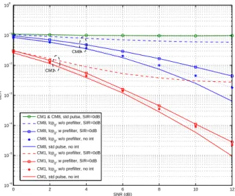
When the two detection schemes are compared, it is shown that the gain of joint detection depends on the joint system activity values and the considered receiver

bas¸ka bir bant kullanılması, e˘ger ortak bant kullanılacaksa iletimin geciktirilmesi veya istenilen frekanslarda ani d¨us¸ ¨us¸ sa˘glayabilmek ic¸in darbelerin

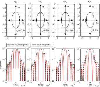
For that, we use linearly combined pulses (as suggested by the standard) that can generate notches at the desired frequencies, present coherent and noncoherent receiver structures

Psoriazis tedavi ve takibinde güncel olarak öneriler; sistemik bir hastalık olan psoriazise yaklaşımımıza, gerekli görüldüğünde sistematik ve tamamlayıcı olarak