DESIGNING A CAN BASED ATM FIELDBUS
Mahmut TENRUH, İlhan TARIMER
Muğla University, Technical Education Faculty, Department of Electronics and Computer Education, 48000/Muğla
Geliş Tarihi : 02.06.2005
ABSTRACT
The Controller Area Network (CAN) bus was initially introduced for automotive applications, but due to its low cost, high speed and high reliability, it has also become a standard in industrial distributed real-time control applications. Asynchronous Transfer Mode (ATM) is a high speed network technology that aims to combine all types of communication, that is, data, voice, and image in a single network structure. Various studies have been carried to incorporate existing network types such as Ethernet and Token Ring with ATM. It is also important to cover the FieldBus communication in this concept. This study aims to incorporate ATM technology with the FieldBus communication. In this concept, CAN based ATM bus structure is introduced. This structure also introduces an opportunity to connect FieldBus networks with ATM seamlessly. Simulation studies have been carried out to validate the introduced model and the results showed that it is feasible to implement the system.
Key Words : Controller Area Network (CAN), ATM, Real Time Control, Industrial Communications.
KONTROLÖR ALAN AĞI ESASLI BİR ATM ALAN TAŞITININ TASARLANMASI
ÖZET
Kontrolör Alan Ağı (KAA) taşıtı başlangıçta otomotiv uygulamaları için önerilmiş fakat düşük maliyeti yüksek hızı ve güvenilirliği sayesinde endüstriyel dağılımlı gerçek zamanlı kontrol uygulamalarında da bir standart haline gelmiştir. ATM veri, ses ve görüntü gibi tüm haberleşme türlerini bir network yapısı içerisinde birleştirmeyi hedefleyen hızlı bir ağ teknolojisidir. Ethernet ve Token Ring gibi mevcut ağ türlerinin ATM ile bağlanması için çeşitli çalışmalar sürdürülmüştür. Kontrol Taşıtı haberleşmesinin de bu çerçevede ele alınması önem taşımaktadır. Bu çalışma ATM teknolojisinin Kontrol Taşıtı haberleşmesi ile birlikte kullanılmasını amaçlamaktadır. Bu kapsamda KAA esaslı ATM Taşıt yapısı sunulmaktadır. Bu yapı aynı zamanda Kontrol Taşıt ağlarının ATM ağları ile doğrudan bağlanabilmesi için de bir imkan sunmaktadır. Önerilen modelin geçerliliğini görmek amacıyla simülasyon çalışmaları yürütülmüş ve sonuçlar sistemin ek avantajlarla uygulanabilir olduğunu göstermiştir.
Anahtar Kelimeler : Kontrolör alan ağı (KAA), ATM, Gerçek zamanlı kontrol, Endüstriyel haberleşme.
1. INTRODUCTION
CAN has an attractive protocol structure with its low cost and high performance, and is accepted as a standard Fieldbus in many industrial environments. The CAN protocol has a robust error handling mechanism and it uses a priority-based collision-free medium access method. This assures that the highest
priority message will always be transmitted first with guaranteed message latency. On the other hand, this method limits the bus length and a CAN bus has to operate, for example, at 40 m bus distance with 1 Mbps bus speed (Anon., 1993; Uphoff, 1994; Lawrenz, 1997).
ATM is a network technology that provides services for all types of communication traffic such as data,
voice, and video. ATM is based on fixed size cell length and connection-oriented switched networking. An ATM cell is comprised of 53 bytes that include a 5-byte header and a 48-byte payload field.
As the progress in network communication goes towards meeting all requirements under the single network technology ATM, it is also necessary to cover the FieldBus technology in this concept (Hwang and et al., 1998; Neves, 1999). Deployment of ATM technology is only possible by a step-by-step procedure. In this scheme, the first step-by-step is to allow the existing network technologies to operate with emerging ATM technology. In order to interconnect existing networks with ATM some solutions, such as LAN Emulation (LANE) and Multiprotocol over ATM (MPOA), have already been introduced (Black, 1998). LANE, for example, uses a procedure that encapsulates the data produced by a Legacy LAN and implements some processes to solve the addressing problem between the LAN and ATM. This solution requires a set of complicated processes for the interconnection of the legacy LANs and ATM. Several solutions have been proposed to solve interconnections problem between fieldbuses and other LAN types such as Ethernet as well as ATM (Ekiz and et al., 1996; Stipidis and et al, 1998; Özçelik and et al, 2001; Fuchs, 2002; Özçelik and et al., 2002; Ertürk, 2002; Siegmund and Muller, 2002). Some solutions are also introduced with wireless ATM (Eng, 1995; Karol and et al, 1997; Dellaverson, 2001).
In a solution that uses remote bridging for interconnection method, CAN messages can be encapsulated in ATM cells (Tenruh and et al, 2000; Tenruh and et al., 2000a). Although the use of remote bridging can meet the requirements of this specific interconnection model, the communication is still realised by using totally different network technologies. As a second step to combine the FieldBus technology with ATM in a single network technology, the ATM protocol can be used in FieldBus.
A solution introduces sending CAN messages over wireless ATM, but it can only carry one CAN message in one ATM cell, which causes the waste of bandwidth. Because while a standard CAN message consists 108 bits, an ATM cell payload field can carry 48 bytes (384 bits) (Ertürk, 2005).
This paper introduces such a solution that uses the ATM protocol efficiently in a CAN based FieldBus network. This solution provides an opportunity to connect FieldBus networks with ATM seamlessly, as aimed for in the ATM concept of integrating all
communication types under a single network technology.
2. MESSAGE DELIVERY
CHARACTERISTICS
In real time systems, it is important to guarantee the delivery of messages to their deadlines. The message deadlines depend on the degree of delay tolerance of the corresponding application. Soft real-time systems can compensate for occasional message delays or even losses, depending on the robustness of the application. Hard real-time systems have strict message deadlines. Three fundamental factors that effect message delay and losses are the MAC protocol, the burstiness of the traffic, and the bandwidth of the communication system (Dean and Buhargav, 1996; Yun, and et al., 2000).
If the medium access protocol is probabilistic and collision based, as in LON (Tenruh and et al., 2000), the contention is resolved by waiting random times where message delays are experienced as a result. In CAN, a collision-free and priority based protocol model is used. In this method, the high priority messages have guaranteed message delays, while lower priority messages may experience more delays if too many high priority messages are generated and the bus bandwidth is low.
3. WORST CASE DELAY ANALYSIS
OF CAN
The probability of an arbitration delay and the chances of losing two attempts at arbitration are very low at low bus utilisation. However, when the bus utilisation gets higher, the delay experienced by messages, especially low priority ones, also becomes higher. For fixed-priority scheduling systems (Audsley and et al., 1991) like CAN, the mathematical analysis for worst-case message delay can be made as follows (Tindell and et al., 1994; Tindell, 1994a; Lawrenz, 1997; Sjodin and Hansson, 1998). The analysis makes some simple assumptions:
• A given message m cannot be generated more than once every Tm time units.
• Once generated, message m cannot take longer than Jm to queue for transmission by
the CAN controller.
• The software drivers for the CAN controller ensure that whenever arbitration starts on the bus, the highest priority message at the node is entered into arbitration first.
With these assumptions, it is possible to determine the worst-case delay (Rm) of a message. Rm is the
delay from the time message m is queued in the CAN controller to the time m is transmitted successfully. The priorities are assigned according to the deadlines. The message with the shortest deadline is assigned the highest priority, the message with the next shortest deadline, the next highest priority and so on. The worst case message latency is experienced when a message is generated with all other messages. Statistically, the worst case latency (Rm) of a message is the sum of the queuing time and
the transmission time (Lawrenz, 1997):
Rm = Jm + wm + Cm (1)
Where the term Jm is the queuing jitter of message
m, and gives the latest queuing time of the message. Messages are queued by software running on the host CPU, and it takes a bounded time to queue a message. As this time is bounded, instead of fixed, there is some variability or jitter between subsequent queuing of the messages. The worst case queuing time wm is measured as the time from the start of
queuing the message m to the arbitration that the message is successfully transmitted. This includes the time taken by higher priority messages and a lower priority message that has already obtained the bus. The transmission delay Cm is the time spent to
send the message on the bus. The transmission delay is calculated from the maximum size of the message and the maximum number of stuff bits that can be inserted into the bit stream during the message transmission. This can be calculated as (Lawrenz, 1997) : m m m 34 8S C 47 8S 4 ⎧⎡ + ⎤⎫ =⎨⎢ ⎥⎬+ + ⎣ ⎦ ⎩ ⎭ (2) Where Sm is the size of message m in bytes. Tbit is
the time of the bus. For example, if the bus bit-rate is 1 Mbps, the bit-time is 1 µs. In the equation, the divisor is given as 4 instead of 5, even though CAN has a stuff width of 5-bit. This is because stuff bits themselves are also subject to bit stuffing and a stuff bit may bring the following four possible equal level bits to a stuff bit required position. It can be seen clearly from the following example:
…1111000011110000…
If a stuff bit is inserted at the start of this stream because of the preceding five equal level bits, the resulting stream becomes:
…11111000001111100000…
This is the extreme bit-stuffing situation that might never occur, but theoretically it must be taken into account as a worst-case possibility. In the equation, the 47–bit is the overhead size and the 34-bit is the part of the overhead which is subject to bit-stuffing. To calculate the maximum queuing delay as wm, the
worst-case time a lower priority message can hold the bus before arbitration must be taken into account. Besides the lower message blocking time, the effect of higher priority messages that can be sent before message m while it is in the queue must also be calculated. A detailed explanation about the queuing delay calculation of CAN messages can be found in references ( Tindell and Burns, 1994; Tindell, 1994; Lawrenz, 1997).
When the equation to calculate the transmission time on the bus is rewritten for an ATM cell, the result is:
m m(ATM ) m bit 53 8S xt C 82 8S xt T 4 ⎧⎡ + + ⎤ ⎫ =⎨⎢ ⎥+ + + ⎬ ⎣ ⎦ ⎩ ⎭ (3)
Where Cm(ATM) is the time spent to transmit an ATM
cell with maximum size after bit stuffing. As the number of bits used in the ATM header is based on the extended version of the CAN frame, 19 bits must be added to the previous 34-bit standard frame header, which results in a 53-bit header subject to bit stuffing. As the 47-bit total standard frame overhead is also extended in the new frame, it becomes an 82-bit field. In this equation, the xt field represents the extra bit number used between data units and padding field. Unlike a CAN frame, an ATM cell has a fixed frame size and it makes the calculation simpler. When the Sm field is calculated for 5
message units each with 8-byte data, the total data field becomes 40 bytes. With additional stuffing bits, this becomes 99 bits for the worst case in this equation and the total worst case message transmission time is 523 µs. Without bit stuffing, a normal ATM frame can be transmitted in 424 µs, which is the time spent for transmitting a 424-bit ATM cell at 1 Mbps bus speed.
4. MODELLING OF ATM FIELDBUS
In the proposed model, basic CAN specifications are applied. Therefore, modification requirements from both hardware and protocol points are kept to a
limited level. A basic ATM FieldBus module is shown in Figure 1. This model has exactly the same structure as a normal CAN node. The only difference is the controller unit used. In this model, instead of a CAN Controller, a CAN based ATM Controller is used. Figure 2 shows the simplified block diagram of the ATM Controller. The structure of this model is based on Intel 82527 CAN Controller (Anon., 1995; Lawrenz, 1997). The ATM Protocol Controller realises the processes required for mapping data in ATM FieldBus Protocol cells. Unlike CAN frames, ATM FieldBus cells have fixed 53-byte frame size. The fixed-size cell structure provides the FieldBus technology with the fast processing advantage of ATM. Using the ATM cell structure may also provide an opportunity to interconnect the ATM FieldBus directly with ATM via modified switches.
H o st C o n tro lle r A T M C o n tro lle r T ra n sc e iv e r D a ta C o n tro l R x T x P h y -B u s Figure 1. The structure of an ATM FieldBus node.
CPU Interface Logic RAM ClockOut ATM Protocol Controller Port 1 Port 2 Adress/ Data bus Control bus Tx/Rx Figure 2. Block diagram of an ATM FieldBus Controller.
Figure 3 shows the ATM FieldBus cell structure. Two methods can be applied in order to map data in ATM cells. The first is mapping the data directly into the data field of the cell. In this process, the data to be mapped must be large enough to fill the data field of the cell. This method can be used to carry fragmented long data streams. This method can also
be implemented in intelligent building applications (Stipidis, Li and Powner, 1998).
The second method aims to carry shorter data fields in one ATM cell. This method can be used to transmit CAN-size data fields. As in a CAN environment the data size is usually small, it is possible to carry more than one message in one ATM cell. Figure 3 shows the structure of the protocol to carry multiple CAN data fields. Each data segment is allocated to a different data unit (DU) and messages are not assigned different priorities. Instead, a common identifier is used in the header of the ATM cell. Therefore, the receiver node first accepts the whole cell and then uses the message object or objects of interest. Before transmission, any unused field in the frame is filled with padding bits. The padding field can also be seen as reserved bits for future use. Data units contain fixed 8-byte data and 4-bit end of data unit (EOD) fields (Cena and Valenzano, 1999).
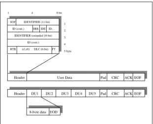
SOF IDENTIFIER (11-bit) ID (cont.) SRR IDE ID…
IDENTIFIER (extended 18-bit) ID (cont.) RTR (r1,r0) DLC (6-bit) FT
Header User Data Pad CRC ACK EOF 1 4 8 bit 1 2 3 4 5 byte
Header DU1 DU2 DU3 DU4 DU5 Pad CRC ACK EOF
8-byte data EOD
Figure 3. ATM FieldBus protocol structure. In the header of the cell, the extended CAN identifier field is mapped. In this application the r0 and r1, which are reserved bits in the CAN protocol, are used as a part of the DLC field to indicate the total size of data field. This header exactly fits into the 5-byte ATM header field. The last bit of the header is used to indicate the Frame Type (FT), which shows whether the data field is filled with a single message or multiple CAN data units. The CRC field is also extended to 32-bits in this proposal, compared to 16-bits in a normal CAN frame. Start of frame (SOF), substitute remote request (SRR), remote transmission request (RTR), identifier extension (IDE), and data length code (DLC) fields have the functionalities as described in CAN standards (Lawrenz, 1997). This protocol uses exactly the same medium access method as CAN.
In order to investigate the performance of the proposed model, some simulation models were simulated with a commercial software package. First, the simulation model for the normal CAN protocol was used. The second was an ATM FieldBus model. In the ATM FieldBus model, ATM cells carrying single and multiple messages were used. Bus communication speed was set to 1 Mbps. As can be seen from Figure 4, ATM nodes were connected to from 1 to 5 message sources. One message source represents the ATM node producing ATM cells carrying a single message and the other ATM nodes produce ATM cells with multiple data units.
Figure 4. Implementation of ATM FieldBus simulation model.
5. SIMULATION RESULTS
The simulation models were tested under various traffic load conditions and results were evaluated. ATM FieldBus and CAN results were also compared. Figure 5 shows the bus throughput results for ATM and CAN bus models. As can be seen from the figure, under the same message iteration conditions, the ATM FieldBus model has higher throughput. This is the result of the ATM cell-size. As the ATM cell-size is larger than an average CAN frame, the ATM FieldBus model gives higher throughput for the same message iteration period.
0 2 0 0 4 0 0 6 0 0 8 0 0 1 0 0 0 1 2 0 0 0 2 4 6 8 1 0 1 2 1 4
M e s s a g e ite r a tio n p e r io d (m illis e c o n d )
B u s th ro ughput (k bps ) a tm c a n
Figure 5. Bus throughput comparison of ATM and CAN buses.
The relationship between message number produced by the models and bus throughput can be seen in Figure 6. In this figure, the amount of data produced by the CAN system is higher than that of the ATM FieldBus model. The size of an ATM cell is almost four times as large as the maximum size of a CAN frame. Therefore four CAN messages give almost the same amount of bus throughput as an ATM cell. It can be argued that if the message size is increased, the amount of delay for real-time applications becomes higher. This reduces the capabilities of the system to meet hard-real-time requirements. That is true to some extent, but ATM cell size is within acceptable limits for a FieldBus system and can meet the real time requirements of the system.
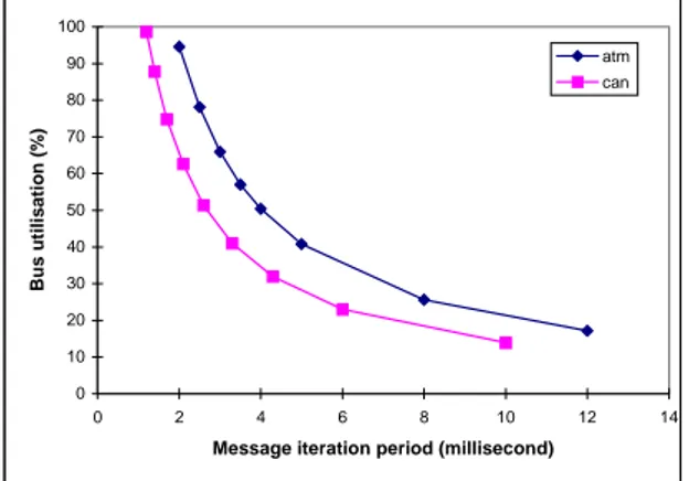
0 2000 4000 6000 8000 10000 12000 14000 0 200 400 600 800 1000 1200 Bus throughput (kbps) Me ss ag es p er se co nd atm can Figure 6. Message number against bus throughput. Figure 7 shows the bus utilisation values against the message iteration values of the models. This figure gives similar results to the previous ones. Again, as the frame size of an ATM cell is larger than a CAN frame, ATM FieldBus model gives much higher bus utilisation value for the same message iteration period. 0 10 20 30 40 50 60 70 80 90 100 0 2 4 6 8 10 12 14
Message iteration period (millisecond)
Bu s ut ili sa ti on (% ) atm can
Figure 7. Comparison of bus utilisation values of the models.
CAN/ATM Fielo:ll:ll!:
-+-Figure 8 shows the average message delay results for ATM FieldBus and CAN models. As discussed earlier, because of larger cell size, the ATM FieldBus model has higher message delay values than the CAN model. An ATM cell has a 424-bit frame size and this is almost four times as large as the maximum size of a CAN frame. The delay values were derived from the average delays of different priority messages in both models. The results show the message delay differences of both models 0 200 400 600 800 1000 1200 0 20 40 60 80 100 120 Bus Utilisation (%) A ver age Messa ge D e lay (M icr o sec ond) atm can
Figure 8. Average message delays.
Although the ATM FieldBus model has higher message delays, these are still within acceptable limits for a real-time system. In addition, the message delay in the ATM FieldBus model with 1 Mbps will not be more than the message delay in a CAN model with 250 kbps bus speed. When compared to some other alternative FieldBus systems, it can be seen that the ATM cell-size is within normal limits (Dean and Buhargav, 1996; Lawrenz, 1997). Figure 9 illustrates different priority ATM cell delays against bus throughput. ATM cells are considered to be carrying single and multiple messages. The ATM cell carrying a single message is assigned the highest priority. This cell is considered to be allocated for hard real-time applications. As can be seen from the figure, this message has a very low and guaranteed message latency, and always will be delivered first. The other priority cells contain from 2 to 5 messages. The priority order is assigned from high to low according
to the number of messages, that is, higher priorities are assigned to the cells carrying fewer message types. 0 200 400 600 800 1000 1200 1400 1600 1800 2000 0 200 400 600 800 1000 1200 Bus throughput (kbps) Message d e lay (Mi c ro second) 5 messages 4 messages 3 messages 2 messages 1 message
Figure 9. Message delays with different priorities and data units.
However, the priority assignment can be made in reverse order or in any order according to the deadlines of the messages. The lower priority cells are assigned to less urgent soft real-time messages, which are used to improve the quality of the system and do not have critical effect in the case of message loss. The message latency results seen in this figure are within acceptable deadline limits for most applications when compared with the SAE Benchmark deadlines (Tindell and Burns, 1994; Lawrenz, 1997).
In the case of multiple message allocation in one ATM cell, the queuing delay must be considered for individual messages. For example, in the case of five-message allocation, the first message must wait until the fifth message before the cell is transmitted. This may cause very long queuing delay if the message arrival period is long. For this reason, in an ATM node, the data units must be received from the sources in acceptable time periods.
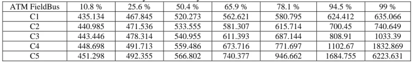
Table 1 shows the message latency values in microseconds for ATM FieldBus model. This table includes five different priority ATM cell end-to-end delays.
Table 1. ATM Cell Transmission Delays With Priority And Bus Utilisation Values.
ATM FieldBus 10.8 % 25.6 % 50.4 % 65.9 % 78.1 % 94.5 % 99 % C1 435.134 467.845 520.273 562.621 580.795 624.412 635.066 C2 440.985 471.536 533.555 581.307 615.714 700.45 740.649 C3 443.446 478.314 540.955 611.393 687.144 808.91 1033.39 C4 448.698 491.713 559.486 673.716 771.697 1102.67 1832.869 C5 451.298 492.355 566.802 740.377 946.662 1684.755 6223.631
Each ATM cell carries from 1 to 5 data units as explained earlier. This method was also used for piggybacking the SAE Benchmark messages in CAN frames (Tindell and Burns, 1994; Lawrenz, 1997). The change of message latency values by the priority and bus utilisation values are given in the table. The message latency values increase at higher bus utilisation values, especially for lower priority messages where latency becomes even higher as expected. This table gives an opportunity to compare the results with the SAE Benchmark deadline values. The benchmark has 5, 10, 20, 100, and 1000 millisecond latency for various priority messages. From these results, it can be concluded that the proposed system meets the benchmark latency requirements.
6. CONCLUSION
This paper investigates the possibility of implementing ATM integration in the FieldBus technology using CAN basics. This application also provides two opportunities for CAN applications. The first is to incorporate CAN with ATM technology, and the second is to extend the limited size of CAN over larger distances. As ATM provides an opportunity to implement both LAN and WAN applications in a single network technology and it offers the required services for all types of traffic, CAN applications can also be implemented over larger distances. The use of ATM based cell structure can provide the opportunity to interconnect the proposed model directly to ATM by switches. Some simulation models were used to investigate the performance of the proposed model. The simulation results for both proposed model and CAN model were compared. These results showed that it is feasible to implement a CAN based ATM FieldBus for real-time applications.
7. REFERENCES
Anonymous, 1993. International Standard ISO 11898. Road Vehicles – Interchange of Digital Information – Controller Area Network (CAN) for High Speed Communication .
Anonymous, 1995. Intel Data Sheet, “82527 Serial Communications Controller, Controller Area Network Protocol,” Intel Corp.
Audsley, N. C., Burns, A., Richardson, M. F., Wellings A. J. 1991. “Hard Real-time Scheduling:
Deadline-Monotonic Approach”, Proc. 8th IEEE
Workshop on Real-time Operation Systems and Software, Atalanta, p-p 133-137.
Black, U. 1998. ATM Volume III : Internetworking With ATM, Prentice-Hall. Inc., USA.
Cena, G., Valenzano, A. 1999. “Enhancing the
efficiency of Controller Area Networks”,
Proceedings ICC’99 The 6th International CAN Conference, Italy, pp. 5/11-18.
Dean, A. G., Buhargav, B. P. 1996. “Embedded
Communications,” Proc. Embedded Systems
Conference, Santa Clara, CA.
Dellaverson, L. 2001. http://www.atmforum.com/, “Putting the Case for Wireless ATM”, ATM Forum. Ekiz H., Kutlu A., and Powner E.T. 1996. “Design
and Implementation of a CAN/Ethernet Bridge”,
Proceedings of the ICC’96, 3rd International CAN Conference, pp.1117 – 1126, France.
Eng, K.Y., Karol M., Veemraghaven M., Ayanoğlu E., Woolworth C. and Yalensuela R.A. 1995. “A Wireless Broadband ad-hoc ATM Local-area Network”, ACM/Bahser Wireless Networks Journal, Vol. 1, Issue 2, pp.161 – 174.
Ertürk, İ. 2002. “Remote Access of CAN Nodes in
a Traffic Control System to a Central Unit over Wireless ATM”, Mobile and Wireless
Communications Network, IEEE CNF 2002, 4th International Wo. Conf., Page (s):626 – 630.
Ertürk, İ. 2005. “A New Method for Transferring CAN Messages Using Wireless ATM”, Journal of Network and Computer Applications, Vol. 28(1), pp.. 45 – 56.
Fuchs, M. 2002. “Bluetooth Wireless Technology Meets CAN”, CAN Newsletter, Vol.1, pp.18 – 24. Hwang, M., Jeon Y., Kim J. 1998. ”ATM-based Plug-and-play Technique for in-home Networking”, Electronic Letters, IEEE JNL 1998, Volume 34, Issue 22, Page(s):2088 – 2090.
Karol, M., Eng K.Y. and Ayanoğlu E. 1997. “Wireless ATM : Limits, Challenges and Proposals”, Bell Laboratories Technical Report, NJ. Lawrenz, W. 1997. CAN System Engineering From Theory to Practical Applications, Springer-Verlag Inc., New York.
Neves, J. 1999. “Modular Architecture for High
Flexibility ATM Based Control System”,
APCC/OECC ’99. Fifth Asia-Pacific Conference on Optoelectronics and Communications, IEEE CNF, Volume 1, Page(s):275 – 278.
Özçelik, İ., Ertürk İ., Ekiz H. and Selçuk F. 2001. “Design and Implementation of a CAN/ATM
LAN Bridge”, Proceedings of ELECO 2001, 2nd
International Conference on Electrical and Electronics Engineering, pp.256 – 260, Turkey. Özçelik, İ., Ertürk İ., Ekiz H. and Selçuk F.. 2002. “Performance Analysis of a CAN/ATM LAN
Bridge Under Various Loads“, CS&I’2002, The
Sixth International Conference on Computer Science and Informatics, pp. 314 – 318, Durhan, NC, USA. Siegmund, R., Muller D. 2002. “A Novel Synthesis
Technique for Communication Controller Hardware Data Communication Protocol Specifications”, Design Automation Conference,
IEEE CNF 2002, Proceedings 39th, Page(s) : 602 – 607.
Sjodin, M., Hansson H. 1998. “Improved
Response-time Analysis Calculations”,
Proceedings, The 19th IEEE CNF 1998, Page (s) : 399 – 408.
Stipidis, E., Ekiz H., Ertürk İ. and Powner E. T. 1998. “The Real to Fully Integrated control
Systems with ATM”, Proceedings of EROPTO
International Symposium on Broadband European Networks, Vol. 3408, pp. 328-336, Switzerland.
Stipidis, E., Li S. and Powner, E. T. 1998. “Intelligent Building Systems: System Integration
using ATM”, ICATM’98, 1st IEEE International
Conference on ATM, France.
Tenruh, M., Stipidis, E., English, M. J. 2000. “Extending Controller Area Networks over
ATM”, ISCIS’2000 The 15th International
Symposium on Computer and Information Sciences, Istanbul, Turkey.
Tenruh, M., Stipidis, E., English, M. J. 2000. “Performance Analysis of CAN/ATM Bridging”, CAN Newsletter, Issue 3, pp. 24-25.
Tindell, K. 1994. “An Extendible Approach for Analysing Fixed Priority Hard Real-time Tasks, Real-Time Systems”, 6 (2), pp. 133-151.
Tindell, K., Burns, A. 1994. “Guaranteeing
Message Latencies on Controller Area Network
(CAN)”, Proc. 1st International CAN Conference,
Germany.
Uphoff, J. 1994. “Theories and Practical
Experience with CAL-based Industrial Control”,
Proceedings of the ICC’94, 1st International CAN Conf., pp. 6 – 31, Germany.
Yun, K.Y., James K.W., Fairlie-Cuninghame R. H., Chakraborty S. C. 2000. “A Self-timed Real-time Sorting Network”, Very Large Scale Integration (VLSI) Systems, IEEE JNL 2000, IEEE Transactions on, volume 8, Issue 3, Page (s) : 356- 363.