BIO-INSPIRED PAPER PLANT ROBOTS:
ARTIFICIAL HELIOTROPISM AND NYCTINASTY
THROUGH TRANSPIRATION
A THESIS SUBMITTED TO
THE GRADUATE SCHOOL OF ENGINEERING AND SCIENCE
OF BILKENT UNIVERSITY
IN PARTIAL FULFILLMENT OF THE REQUIREMENTS FOR
THE DEGREE OF
MASTER OF SCIENCE
IN CHEMISTRY
By
Süleyman Doruk Cezan August 2019
ii
BIO-INSPIRED PAPER PLANT ROBOTS:
ARTIFICIAL HELIOTROPISM AND NYCTINASTY
THROUGH TRANSPIRATION
By Süleyman Doruk Cezan August 2019
We certify that we have read this thesis and that in our opinion it is fully adequate, in scope and in quality, as a thesis for the degree of Master of Science.
____________________ Bilge Baytekin (Advisor)
____________________ Onur Özcan
____________________ Akın Akdağ
Approved for the Graduate School of Engineering and Science:
____________________ Ezhan Karaşan
ABSTRACT
BIO-INSPIRED PAPER PLANT ROBOTS:
ARTIFICIAL HELIOTROPISM AND NYCTINASTY
THROUGH TRANSPIRATION
Süleyman Doruk Cezan M.Sc. in Chemistry Advisor: Bilge Baytekin
August 2019
Self-regulation is a fundamental feature of all living systems, which maintains their metabolic activities through biochemical feedback loops. Those feedback loops respond to environmental stimuli, and therefore the organism displays ‘embodied intelligence’. Despite the complexity of these feedback loops, using them as a source of inspiration can open new endeavors in soft robotics to design self-regulating systems, and ultimately to fuse embodied intelligence into soft robots. Here we show some simple systems, in which plant-inspired soft robots display heliotropism (tracking the sun) and nyctinasty (opening and closing its leaves) through material feedback and artificial transpiration for self-regulation – all being examples of embodiment of intelligence. First, materials feedback is adapted to a hard robotic system behaving similar to a soft robot, displaying heliotropism and nyctinasty by using the phase transition of shape memory alloy springs. Then, artificial transpiration is integrated into a soft robotic system, using swelling/deswelling of hydrogels on the paper body by using origami/kirigami strategies. Both material and transpiration feedback involve stabilization with cycles of traction and contraction (of shape memory alloys, or hydrogels) events that keep the robots at a metastable state, maximizing of solar flux on the leaves (decorated with solar panels) for higher efficiencies of harvesting light. Moreover, the feedback mechanism of the hydrogel-based system can be advanced by using hybrid hydrogels (e.g. an addition of thermoresponsive hydrogels), or doping the gel with light-absorbing chemicals, or altering the geometrical design of the systems. Finally, achieving self-regulation in soft robots through material/transpiration feedback is important to attain the embodiment of intelligence in them, and this may have implications extending from energy efficiency to adaptability in autonomous soft robots.
iv
ÖZET
DOĞADAN ESİNLENEN KÂĞIT BİTKİ ROBOTLAR:
TRANSPİRASYON İLE YAPAY HELİOTROPİZM VE
NİKTİNASTİ
Süleyman Doruk Cezan Kimya, Yüksek Lisans Tez Danışmanı: Bilge Baytekin
Ağustos 2019
Kendi kendini denetleyebilme yeteneği, yaşayan sistemlerin metabolik aktivitelerini sürdürebilmesi için gerekli olan, biyokimyasal geri bildirim döngüleri ile sağlanan, en temel özelliklerinden biridir. Bu geri bildirim döngüleri yaşayan organizmada, çevresel uyarıcılara karşı tepki verirken, cisimsel zekânın oluşmasını sağlar. Bu geri bildirim döngüleri kompleks olsa dâhi, bunları esin kaynağı olarak kullanmak, yumuşak robotlarda kendi kendini denetleyebilme yeteneğini ve en nihayetinde cisimsel zekâyı yumuşak robotlara entegre etmek için yeni uğraş alanlarının açılmasını sağlayabilirler. İşte bu aşamada basit, bitkilerden esinlenen yumuşak robotları gösteriyoruz, bu robotlar kendi kendini denetleyebilme yeteneğini ve nihayetinde cisimsel zekâ için, heliotropizm (güneşe yönelim) ve niktinasti (yapraklarını açıp kapatma) yeteneklerini malzeme geri bildirimi ve yapay terleme kullanarak gösterebilirler. Öncelikle, malzeme geri bildirimi sert fakat yumuşak robot gibi hareket eden bir robotik sisteme akıl hafızası olan alaşımları kullanılarak adapte edildi. Sonrasında, yapay terleme yumuşak robot sisteme, origami/kirigami stratejileri kullanılarak hazırlanmış kâğıt robot vücutlar üzerinde hidrojellerin şişmesi/daralması entegre edildi. Her iki malzeme ve terleme geri bildirim mekanizması, salınma ve gerilme olaylarının robotun vücudunu yarı kararlı halde tutarak ışık toplama verimliliğini arttırmak için, güneş akısını yapraklar (güneş panelleri yerleştirilmiş) üzerinde maksimize etmesine yarar. Bununla birlikte, hidrojel bazlı geri bildirim mekanizması, hibrit hidrojeller kullanılarak (ısıya duyarlı jellerin eklenmesi ile), ya da ışığı soğuran kimyasallar ile jelleri katkılayarak, veyahut sistemin geometrileri değiştirilerek geliştirilebilmektedir. Sonuç olarak, malzeme/terleme geri bildirimi, kendi kendini denetleyebilme yeteneği olan yumuşak robotlar eldesi için önem arz etmekte ve enerji veriminden, adaptasyon yeteneğine kadar birçok alanda önemli sonuçları sahiptir.
Acknowledgment
I am inexpressibly grateful to my supervisor Prof. Bilge Baytekin for her patience, guidance and support during my undergraduate and masters work. Her foresighted vision, patience, and teaching always boosted me and the impact of our work by many orders of magnitude. I especially would like to thank her for establishing a lovely research environment for us, the group members.
I am indefinably thankful to Prof. Tarik Baytekin for his teaching, inspiration, and being outstanding example as a scientist. I am grateful for the privilege of meeting Prof. George Whitesides & Prof. Bartosz Grzybowski, who rejuvenated my mind. I especially would like to thank Prof. Bartosz Grzybowski for his contribution and guidance in the initial stages of this work. I would like to thank all members of Bilkent University Chemistry Department (especially Prof. Emrah Özensoy), Whitesides’ Research Group (especially Dr. Barış Ünal) for providing inspiration, teaching, and multidisciplinary research atmosphere and joyful friendship. I especially would like to thank my professors Dr. Emrah Özensoy, Dr. Burak Ülgüt, and Dr. Yunus Emre Türkmen for their perfect teaching, and inspiration.
I am grateful to all the jury members Asst. Prof. Bilge Baytekin, Asst. Prof. Onur Özcan, and Assoc. Prof. Akın Akdağ.
I acknowledge The Scientific and Technological Research Council of Turkey (TUBITAK) and for financial support under award 117M004 and Robocom++.
vi
I would like to thank all the group member for the lovely research environment they provided all these years. I am sincerely grateful to my other groupmates and friends (Atakan Arda Nalbant, Işıl Uzunok, Irmak Karakaya, Merve Yence, Selin Ezgi Dönmez) for their friendship. In addition, I would like to thank the ‘Powerlifters of Bilkent’ for the workout motivations, and the lifts. This thesis would certainly be lifeless without their colorful contributions to me.
I would like to thank my mother (Zeynep Demet Yürek), grandmother (Filiz Yürek), aunt & uncle-in-law (Buket & Jonathan Theobald), Keriman & Asım Şekerci (and their sons Mustafa and Ekrem Şekerci), my best friend (Irmak Çabas), and my cat (Şımarık, for the purrs, and the fruitful scientific discussions) for always being there for me. This thesis is dedicated to my mother (Zeynep Demet Yürek). There is no way to thank her for the love, care, dedication, and self-sacrifice she have provided all these years for me.
Table of Content
1. Motivation ... 1 2. Introduction ... 2 2.1. Soft Robotics ... 2 2.1.1. Chemical/Material Feedback ... 5 2.1.2. Embodied Intelligence ... 6 2.2. Plant Robots ... 82.2.1. Actuation in Plant Robots ... 8
2.2.2. Artificial Heliotropism and Nyctinasty ... 10
3. The Next Episode of Soft Robotics ... 11
4. Results & Discussion ... 12
4.1. Artificial Heliotropism and Nyctinasty ... 12
4.1.1. The Plant Robot with Hard Elements: The-Proof-of-Principle ... 13
4.1.1.1. How Material Feedback is used to Build the First of Autonomous Plant Robot ... 14
4.1.1.2. Performance Characteristics ... 20
4.1.2. Paper Plant Robots (PPR) ... 22
4.1.2.1. Transpiration ... 24
4.1.2.2. Choice of Materials ... 25
4.1.2.3. Reversible Actuation of Hydrogel/Paper Folding Structures. 27 4.1.2.4. Heliotropic Plants ... 28
viii
4.1.2.5. Artificial Nyctinasty through Transpiration ... 31
4.1.2.6. The Artificial Transpiration Feedback ... 32
4.1.2.7. Performance Characteristics ... 35
4.1.2.8. Other Designs that can be Attained by Artificial Transpiration and Material Feedback ... 36
4.1.3. Responsive Hydrogels ... 38
4.1.3.1. The Cryptex ... 38
5. Experimental and Supplementary Results ... 40
5.1. Plant Robot: Proof-of-Principle ... 40
5.1.1. Choice of Materials ... 40
5.1.2. Capacitor Charging Potential for Heliotrope and Non-heliotrope ... 41
5.1.3. Nyctinastic Movement by Constriction of Nitinol Springs ... 43
5.1.4. Measurement of Alignment Error in Solar Tracking ... 44
5.2. Paper Plant Robot ... 45
5.2.1. Preparation of Folding Structures and Paper Plant Robot ... 45
5.2.2. Force Measurements ... 50
5.2.3. IR Images and Absorbance ... 51
5.2.4. Performance Measurement ... 51
5.3. Hybrid Responsive Hydrogels ... 52
5.3.1. Synthesis of the Responsive Hybrid Hydrogels ... 53
5.3.2. Preparation of Hybrid Responsive Hydrogel Actuators ... 56
5.3.3. Performances of the Hybrid Responsive Hydrogels Actuators ... 57
6. Conclusion ... 59
List of Figures
Figure 1.1 Chameleon – an example of 8.7 millions of species in nature.[1] ... 1 Figure 2.1 The left column is an example of robotics in industry, the right column is the first example of a soft robot.[3] ... 3 Figure 2.2 The left column is an octopus the source of inspiration, the right column is a bio-inspired soft robot.[4] ... 4 Figure 2.3 a) Artificial chameleon skin design; an example of design of new functional materials via bioinspiration. Chameleon skin (upper row, source of inspiration) has neighboring compartments - with different pigments expressing individual monochromatic colors - which can be mechanically enlarged or shrunk in order to affect the overall apparent color. b) The artificial skin made out of Ecoflex (inspired design), too, has micro to mili meter-sized channels filled with aqueous solutions of dyes that can change volume depending on the mechanical input. A touch on the skin can unequally alter the volumes of these channels. This can be used for touch or deformation sensing or for camouflage in a very similar way nature does in the chameleon skin[17]. Scale bar is 2mm. ... 5 Figure 2.4 (a) is the initial open state of a sensitive plant (mimosa pudica) before a touch, (b) is the closed state of the sensitive plant after a touch.[28] ... 8
x
Figure 2.5 The explanation of reversible actuation mechanism in plants based on osmosis. The tendril-like structures in plants function to design an actuator based on osmosis. Schematic representation and optical images of Tradescantia Zebrina leaves showing two stages (a) close (turgid) (b) open (flaccid), of the stoma cells. Scale bars: 10 µm. (c) and (d) cyclic osmoregulation (c) for plant cell and (d) for an artificial osmotic actuator that is designed taking inspiration from (c).[36] ... 10 Figure 2.6 a) Solar tracking (heliotropism) of plants. Photo taken from [29], which also shows b) the of rate of CO2 production by a heliotropic plant (pinus arizonicus) vs a
non-heliotropic one. ... 11 Figure 3.1 The solar trackers benefitting from material feedback to track the sun autonomously. The left photo is of a computer controller solar tracker; the photo on the middle is a plant robot tracking the position of the sun through material feedback [2], and the right one is of an artificial plant operated by artificial transpiration tracking the position of the light source. [2], [46] ... 13 Figure 4.1 The plant robots performing heliotropism and nyctinasty. (a) Photographs of the heliotropism only system the left (in the dark) and the right (optimizing the solar input by turning toward the source of light). (b) Photographs of the plant robot performing both heliotropism and nyctinasty. The images on the left are in the dark, the plant robot is in its initial state, leaves are closed. The images on the right are under the illumination of light source form a certain (approximately 60O) angle with
the leaves open and the crown turned towards the source of light. Both systems are made out of a 3D printed plastic body with properly positioned nitinol springs, lenses on top of the crown, and solar panels as its leaves, as also shown in Figure 5.1 ... 15
Figure 4.2 The photograph of the first autonomous and functional soft ‘plant’ robot. ... 15 Figure 4.3 The schemes and images of heliotropism-only plant robot. (a) and (b) The lens in the design (Figure 5.1 and 5.2) focuses the light directly on the nitinol springs Local heating and contraction (regions heated by focused light are denoted by red asterisks) bends the crown towards the light source. The left column is for the high elevations of the sun – the spring is heated from its middle region (denoted xm) to the
innermost region xi, resulting in a small contraction and bent of the crown. Whereas,
with the low elevations of the sun, heating starts near the spring's outermost region, xO. The spring contracts more, so the crown is bent further to lower degree angles. The
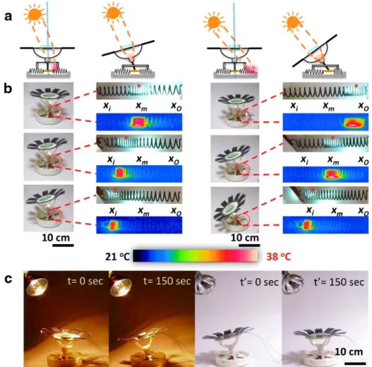
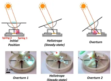
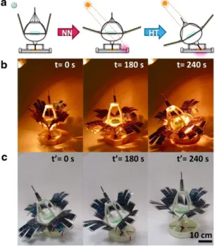
insets are the optical and thermal images of the springs being contracted. (c) the response of the system upon the illumination by a light source (IR lamp, 250 W, General Electric). The bending motion is completed within 2.5 min and reverting back to initial position, which takes place when the light is turned off, takes 2 min. ... 18 Figure 4.4 The optomechanical feedback stabilizing the plant in the position of maximizing solar flux. When spring denoted as “1” is heated by the sunbeam focused through the lens, it contracts and the stem turns toward the sun until the steady-state position is reached. Any additional overturning is prohibited since the beam is then focused between the two springs, or onto spring “2,” in both cases causing retraction of the stem. These two situations are illustrated by the experimental images in the bottom row. Red asterisks give the position of the focal point. ... 20 Figure 4.5 Device capable of both nyctinasty and heliotropism. (a) Scheme of the “plant” exhibiting nyctinastic (NN) and heliotropic (HT) motions simultaneously.
xii
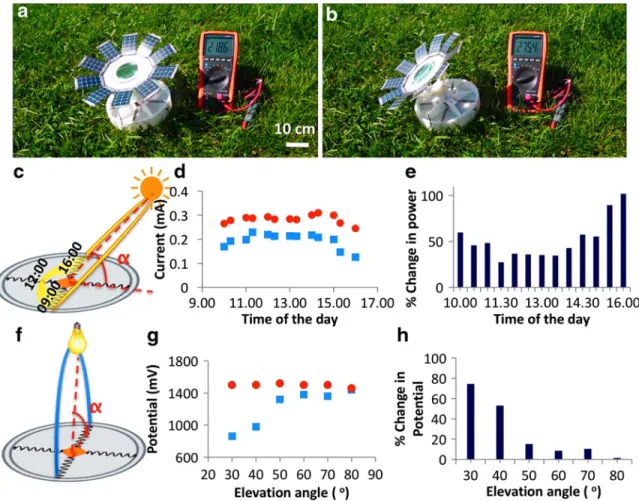
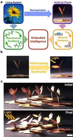
Upon light exposure, four nitinol wires at the top of the “crown” contract such that 16 solar panel leaves open up exposing the inner lens that can then control heliotropic motions. Both nyctinasty and heliotropism cease, when the light is turned off, and the device returns to the initial state. The experimental images (b) upon irradiation with IR lamp, 250 W, General Electric; (c) of the plant's response when light is turned off. ... 21 Figure 4.6 Field performance of the plant robots on a typical summer day in Ankara, Turkey. (a) The initial state of the plant robot. (b) Heliotropism of the plant robot in the morning hours (under the low elevated sun). (c) The elevation angle of the sun, α. (d) Current generated by the solar panels connected parallel as a function of the day time (from 9 AM to 5 PM), for the heliotropic plant robot (red circle markers), and for the non-heliotropic reference robot in which the crown is stationary (blue square markers). (e) The percentage improvement in power generation for the heliotropic device versus the non-heliotropic, immobile stem control (based on the data from (d)). Power enhancement is up to 110% when the sun is low and bending of the stem is essential to capture any appreciable flux of photons. (f) The elevation angle of the artificial light source used indoor, α. (g, h) A similar comparison (heliotropic vs. non-heliotropic design) as in d and e, but based on the ability to load a capacitor connected to the solar panels of the “plant” (for the wiring scheme and further details, see Experimental Section. (In (g), Red circle markers = heliotropic plant, blue square markers = non-heliotropic plant.) ... 23 Figure 4.7 Bio-inspiration and incorporation of embodied intelligence in paper plant robots (PPR). (a) Living systems (plants) are operated by embodied intelligence achieved by biochemical feedback. Embodied intelligence in PPR are attained by
material feedback in a similar way (b) Properly placed hydrogels on origami PPR allows the system to have material feedback. The left column is the initial ‘dark’ state of the PPR with its leaves closed. The right column is the final (metastable) state of the PPR upon the illumination of light with its leaves open (nyctinasty) and bent towards the light (heliotropism). The PPR stays at the metastable state as long as the external stimuli, the light is on. When the PPR is connected to a water source or hydrated by a spray of water intermittently, both motions are regulated autonomously through material feedback (Figure 5.11). (c) A field of PPR is showing a gradient of responses depending on their position with respect to the light source; displaying agile, continuous action (as expected from ‘soft’ robots) controlled by the intensity of the light stimulus. Scale bars are 1 cm. ... 25 Figure 4.8 An example of folding structures using paper and agarose – a paper flower that (reversibly) responds to light stimulus. The paper flower is able to change its leaves position/state upon the illumination of light. The left column is the initial (hydrated state of the flower); the right column is the final dehydrated state of the flower. When the light is turned on the plant goes from initial state (left) to final state (right). If there is a rain or spray of water, the plant goes back to its initial state (left) from the final state (right). The scale bar is 1 cm. ... 29 Figure 4.9 Transpiration mechanism of the paper plant robot (PPR) performing heliotropism. (a) Visible and (b) infrared-red images of the PPR operation. The left column in (a) and (b) is the initial (steady) state of the plant is exposed to light. The water in the hydrogel under the illumination of light evaporates faster than the one under the shadow – as a result, the body bends towards the light source until the shadow of the leaves covers both of the hydrogels. Scale bar is 1 cm. (c) The correlation
xiv
between heliotropic movement (red) and transpiration (blue) is shown. As the plant is bending towards the light source it evaporated the water in the corresponding hydrogel since the solar input is maximized. The plant does not bend more than necessary as the movement stops when the shadow is on the corresponding hydrogel. See also Section 4.1.2.5 for detailed description of artificial transpiration feedback. (d) Adding infrared ‘heaters’ into the hydrogel, here shown the data for exfoliated graphite (EG), increases the speed of heliotropic action without loss of reversibility. ... 32 Figure 4.10 Nyctinasty mechanism and the performance of the paper plant robot. (a) Visible and (b) thermal images of the robot operation. The left column is the initial state of the leaves of the paper plant robot; right column is the final state of the leaves. (b) Thermal images are showing N gel located on the dark side of the leaves kept cold during the nyctinasty movement. Scale bar is 1 cm. (c) ‘Opening’ angle of the left leaf compared to that of the right leaf upon illumination (direction of the light = left, elevation angles = 45O). ... 34
Figure 4.11 Self-regulation mechanism of elevation tracking thorough transpiration feedback in the paper plant robot performing both heliotropism and nyctinasty. (a) Schematic representation and (b) thermal images of the initial and final (steady) states, the latter is attained when the hydrogel muscle loses water and contracts upon light exposure. Any overturning is prevented since the light is blocked by the shadow cast by the leaves of the plant on the muscle. (c) The changes in the amount of water in light (EP=evaporation) and dark (CA=capillary action) cycles. (d) The self-regulated heliotropic action (reflected in the average bending angle recorded at different elevation angles of light (red))of the plant with the ‘roots’ connected to a water-reservoir – the hydrated soil, in comparison to an expected ideal heliotropic
behavior (yellow). (e) The feedback is reversible up to 50 cycles as shown in the snapshots. ... 36 Figure 4.12 Paper plant as a solar tracker. (a) The schematic illustration and photograph of the self-regulated paper robot system, in which a thin solar panel (Flexible Solar Panel SP3-37, Powerfilm) is integrated into the paper plant robot. (b), (c), and (d) potential, current, and power (respectively) generated by the solar panels upon illumination with the light source positioned at different elevation angles, when the system is stationary (blue bars) vs when the system is heliotropic (red bars). (e) The ratio of the power generated by the heliotropic plant vs. the power generated by a non-heliotropic plant (with no muscles, and no feedback) at different elevation angles. The autonomous heliotrope harvests solar energy more than the non-heliotrope at lower elevation angles of the light source; e.g., 6 times more power is obtained for the system operating at light source elevation of 15O. ... 37
Figure 4.13 Stomata design by using auxetic material design. (a) Crease pattern, a schematic representation of the folding types and the photograph of a simple unit of auxetic structure. The length of the mountain fold is 10 mm and the length of valley fold located on the left and right of the mountain fold is 14.1 mm. (b) Isometric-view and top-view photos of the initial (left) and the final (right) states of the auxetic structure with agarose gel (3%, 60 L) on each of the valley folds, upon illumination with an IR lamp, placed at 50 cm distance. The auxetic motion was completed in 40 min for this structure. ... 39 Figure 4.14 The illustration of phase transition of thermoresponsive hydrogels the difference between what is promised in the literature (a generic figure) and what is
xvi
observed. Although the same procedures were used with the expectations of the left column, the results are more like the right column. ... 41 Figure 5.1 3D printed body of plant robot operated by material feedback. The figure is showing how the 3D printed body of the proof of concept plant robot has been designed and assembled. (a) is showing the plant robot actuated by nitinol springs functioning as both a sensor and an actuator. (b) is illustrating the snapshots of the contraction of nitinol springs due to heating by using light. (c) is the SolidWorks images (of .stl files) of the plant robot for 3D printing. (d) is the image of the plant performing both heliotropism and nyctinasty has an additional component (named as "Pistil"). (e) is the SolidWorks images (of .stl files) of the additional part. (f) is the path of the focused light beam throughout the day. The number of springs can be increased to have a smoother and more responsive system on this path. ... 42 Figure 5.2 Combination of lenses for a shorter focal length of plant robot. The figure is showing the integration of two convex lenses to have a focus on shorter distances. Two lenses with diameters 75 mm and 50 mm are combined to have a lens with a focal length of 100 mm. ... 43 Figure 5.3 The performance of heliotropic plant robot compared to non-heliotropic (stationary) plant robot in capacitor charging. The figure shows the capacitor charging potential vs. time for the heliotropic (stationary crown) and non-heliotropic plant robot. (a) the potential vs. time graphs of the capacitor charged by the solar panel (leaves) of the plant robot for various elevation angles of the light source (IR General Electrics, 250W). Red line is for the heliotropic system while the blue lines are representing the non-heliotropic (stationary stem) system. (b) the light source is placed at a certain elevation angle (α) that differs from the normal of the plant robot. (c) the
photo and (d) the schematic representation of the circuit. The heliotrope was operated with the artificial light source (35 W, metal halide) with 4900-5200 lux intensity at a constant 30 cm distance from the heliotrope at given α angle. ... 44 Figure 5.4 Nyctinastic movement by constriction of nitinol springs in the ‘Pistil’ element. The figure is showing the nyctinasty is performed by the pistil part of the plant. (a) is the names of the components used for nyctinasty. The left column is the photograph and right column is the schematic presentation of the pistil. (b) is showing the operation of the nyctinasty. The left column is the initial state of the leaves when the light is off, right column is the metastable state of the leaves when the light is turned on (under IR lamp, 250 W, General Electric, or daylight). The contraction of the springs is shown with the red dashed lines. If the light is off the system will turn back to its initial position. ... 45 Figure 5.5 Measurement of alignment error of the paper plant robot in solar tracking in x- and y- directions. The figure is showing the error in alignment when the system is operated. The left column is for the movement in the x-direction (in degrees). In the bottom part, the deviation (blue dots) from the ideal line (yellow dashed) are shown with the error bars. The right column is for the movement in the y-direction (in degrees). In the bottom part, the deviation (red dots) from the ideal line (yellow dashed) are shown with the error bars. This motion fits the "ideal case" better than for the x-coordinate. Error bars are based on 5 different measurements. ... 46 Figure 5.6 The preparation and mechanism of folding structures. (a) the preparation of folding structures are a combination of hydrogel (agarose, Sigma-Aldrich) and paper. The preparation of the paper-gel structures consists of two steps: 1) A piece of paper (Canson 1557-200 g/m2, 10 mm wide 50 mm long, and 0.5 mm thick) and creating a
xviii
simple folding pattern by engraving the paper at desired crease pattern with a laser cutter (Universal VLS2.30 model, with the settings: power 6%, speed 10%, and resolution 1000ppi). 2) The drop-casting of the uncured gel (agarose, 10-50 mL, 1-3%) on the engraved creased pattern and letting it cure on the paper (Fig. S2). (b) the mechanism of the folding of the hydrogel-paper structures. When the gel is hydrated the folding structure stays at its initial state. When the light is turned on the evaporation wins against capillary action so the gel contracts and the structure folds. If there is no light, and the paper is hydrated, the gel rehydrated because of the capillary action so the structure goes back to the initial state. (c) is illustrating an example of a folding structure operated under a light source (IR General Electrics, 250W). ... 47 Figure 5.7 Performance enhancement of folding structures by doping with IR absorbers/heaters hydrogels. (a) the photograph of the folding structures used in the experiments. The upper one is the graphite doped and the lower one is a regular folding structure. (b) the visible absorption spectrum of the dried gels to show the difference in IR absorbance. (c) folding angle vs. time of the structures after the light is turned on. (d) five cycles performed by the doped and non-doped hydrogels. ... 48 Figure 5.8 Angled crease pattern for pre-programmed folding in 3D. (a) the angled folding pattern that is placed with the angle b (beta). (b) the angle a (alpha) and g (gamma) (c) that are the initial (i) and the final (ii) state of the folding structures with angles crease pattern. Motion in 3D resulting as more folding in the angle g (gamma) with the increasing angle of b (beta). ... 49 Figure 5.9 Single input – multiple outputs (SIMO) in folding structures. (a) the schematic representation of the SIMO folding structure. (b) the simplest example of
designing SIMO by changing the amount of the hydrogel resulting in the change in the amount of the heat needed to move a specific fold. With single input (light), three different movements are achieved. ... 50 Figure 5.10 The preparation and the part of the paper plant robot. (a) illustration of the parts of the paper plant robot and the position of hydrogels. (b) the vector drawing (left) for a 2D laser cutter and the photograph of the cut and engraved paper ready to be folded into the robot. ... 50 Figure 5.11 Water transportation paper plant robot for using capillary action. (a) the integration of filter paper into the body (Canson 1557-200 g/m2, 10 mm wide 50 mm long, and 0.5 mm thick) of the robot. (b) the schematic representation and thermal images showing how water moves only on filter paper without wetting the body material. (c) the contact angle change of a water droplet on filter, regular and waxed papers. Waxed paper is more repelling as the contact angle is high for a longer amount of time. ... 51 Figure 5.12 The force measurement exerted by the folding structures. (a) the circuit used to measure the force. (b) the force and folding angle a (alpha). ... 52 Figure 5.13 The characterization of the folding structures (a) the schematic representation of how the experiments and the measurements have been done. (b) the evaporation rate under the light and no light. (c) the angle change with respect to time depending of concentration. (d) the five cycles performed by the folding structures as a sign of reversibility depending on concentration. (e) the angle change with respect to time (f) the five cycles performed by the folding structures as a sign of reversibility. ... 53
xx
Figure 5.14 The effect of humidity on the folding structures. Two extreme conditions (high: 90%, low:20% relative humidity) are tested. For the high humidity S shape in the change of folding angle is observed, almost two times more time is needed to reach the same folding angle with the one operated under low relative humidity. ... 54 Figure 5.15 Synthesis of PNIPAM hydrogels. Two solutions were prepared to synthesize PNIPAM hydrogels. Solution A was prepared by dissolving 400mg NIPAM (re-crystallized in hexane) and 10 mg BIS(N,N-bis(dimethyl)acrylamide) in 4 mL deionized water; solution B was prepared by dissolving 47mg potassium persulphate in 2 mL water. Before using, the solutions were cooled in an ice bath. Gelation was then carried out by combining solution A and B (A:B is 2:1) and addition of 5 µL of TEMED(N,N,N’,N’-tetramethylethylenediamine). The gelation took ca. 5 minutes to complete. ... 55 Figure 5.16 Preparation of PNIPAM-Agarose hybrid hydrogels. Step 1 is the preparation of agarose and drying the outer shell of the gel out without damaging the structure of it. Then, the contracted hydrogel is swelled with the pre-gel solution of PNIPAM and polymerized to obtain the hybrid hydrogel. This hydrogel has the thermoresponsive abilities of PNIPAM while interacting with water but using the structural integrity of agarose. ... 56 Figure 5.17 Preparation of PNIPAM-Agarose hybrid hydrogels. Step 1 is the preparation of agarose and drying the outer shell of the gel out without damaging the structure of it. Then (step 2), the contracted hydrogel is swelled with the pre-gel solution of PNIPAM and polymerized to obtain the hybrid hydrogel. This hydrogel has the thermoresponsive abilities of PNIPAM while interacting with water but using the structural integrity of agarose. Addition of PPy is simple, due to the initiators of
PNIPAM already presented in the gels. A simple addition of Py on top of the PNIPAM-Agarose hybrid hydrogels will polymerize the diffused Py to PPy in the hybrid hydrogels. ... 57 Figure 5.18 Synthesis of PNIPAM-co-AAm hydrogels. A solution of NIPAM and AAm were dissolved in BIS solution (0.1 mL, 0.032M) with the amounts and ratios given in Table 1. The prepared solution was combined with potassium persulphate (0.25 ml, 0.21M) and TEMED (0.25ml, 0.41M). The gelation took ca. 5 minutes to complete in room temperature. ... 58 Figure 5.19 The step-by-step preparation of folding structures. Step 1 is the preparation of agarose on the folding structure sand drying the outer shell of the gel out without damaging the structure of it. Then (step 2), the contracted hydrogel is swollen with the pre-gel solution of PNIPAM and polymerized to obtain the hybrid hydrogel. This hydrogel has the thermoresponsive abilities of PNIPAM, while interacting with water and has structural integrity of agarose. Addition of PPy is simple, due to the initiators of PNIPAM already presented in the gels. A simple addition of Py on top of the PNIPAM-Agarose hybrid hydrogels polymerizes the diffused Py to PPy in the hybrid hydrogels. ... 59 Figure 5.20 Performance of the hybrid-responsive hydrogels as actuators. (a) the folding angle change with time under light (lux=~5000) for the PPy-Agarose hybrid hydrogels (b) the folding angle change with time under the flux (lux=~5000) for the PNIPAM-Agarose hybrid hydrogels (c) the folding angle change with time under light (lux=~5000) for the combination of PNIPAM-PPy-Agarose (10µL:10µL, 20uL:20uL, 30uL:30uL) hybrid hydrogels (d) the comparison of the best performances of PPy-Agarose, PNIPAM-Agarose and PNIPAM-PPy-Agarose (30uL:30uL). ... 60
xxii
List of Tables
Table 5.1 The amounts of the components in the preparation of PNIPAM hydrogel….56 Table 5.2 The amounts of the components in the preparation of PNIPAM hydrogels NIPAM-co-AAm hydrogels……….56
Chapter 1
1. Motivation
Figure 1.1 Chameleon – an example of 8.7 millions of species in nature.[1]
What is your favorite piece of art? Many people would answer this question with The Persistence of Memory by Salvador Dali or The Weeping Woman by Pablo Picasso. The most breath-taking and mind-stimulating piece of art is, however, perhaps ‘Life’ by Nature. However, it is not a static piece. As Erwin Schrödinger said, “Living matter evades the decay to equilibrium.” If a living system is something that is organized and far-from-equilibrium, would it be reasonable to claim that we can create it? From a far-point view, a straight answer would be “Yes!”. Fundamentally, a living cell is an organic robot that consists of some macromolecules that react and organize in complexity. This complex network of reactions forms a living system – that consumes energy to maintain, develop and respond to the environmental stimuli. Moreover, this network is subject to evolution, meaning it continuously changes itself. In order to design such mesmerizing systems with these abilities, artificially, chemistry, a field that can provide infinite possibilities to create these systems at all scales, can surely contribute. This endeavor includes firstly the understanding of the ways of nature – a
2
valuable exercise that has ramifications in subjects extending from energy to medicine [2]. In these lines, this thesis work focuses on mimicking a living system (plant), tracking sun to increase solar energy efficiency through a feedback mechanism.
Chapter 2
2. Introduction
2.1 Soft Robotics
Figure 2.1 The left column is an example of robotics in industry, the right column is the first example of a soft robot.[3]
Robotics is evolving from sharp-edged, industrial, and metallic systems to curved, humane, and elastomeric systems similar to the transition from equilibrium to non-equilibrium systems[4]. The traditional robotics is hard, using structures like gears, joints, bearings, engines, and hard electronics, mostly composed of metals[5]. Despite few examples of limb-like structures[6], [7], they function by using movement patterns (discrete, and fast) and structures (engines, wheels, and treads) not found in nature[8]. The hard robots can perform the same movement patterns found in nature, but they require delicate electronics, controllers, operators and extra energy to operate all of those components simultaneously, e.g., the Atlas robot of Boston Dynamics[9]. Hard robots need “Thousands (Kilos) of Lines of Code (KLOC)” to mimic the movement
4
pattern of an octopus tentacle, whereas, it can easily be implemented by using soft components like elastomeric polymers, to robots as simple as an on/off switch[10].
Figure 2.2 The left column is an octopus the source of inspiration, the right column is a bio-inspired soft robot.[4]
In the recent years, a new type robotics, named as “soft” robotics, was developed, taking inspiration from nature [5], [8], [11], [12]. Soft robots are mainly made out of soft materials or hard materials tailored to have mechanical compliance (such as metal meshes) that provide a continuum of flexibility to the robot body. The most frequently used group of soft materials for soft robot manufacture is elastomers. These elastomers are molded into body shapes with ‘pockets’ or ‘chambers’ which allow their actuation mostly using pressurized air or vacuum[4], [10], [13]. In addition to cooperativeness (meaning they are safer for human interaction than the harder robots), soft robots are simple to manufacture, cheap, capable of complex movements. These properties, in combination with the mechanical compliance make them much easier to operate and function at several tasks such as grasping soft and/or complex shaped objects, e.g. eggs, fruit, adapting the environment, navigating through constrained environments, forming structures from the body and etc. [10], [14]–[16].
Figure 2.3 a) Artificial chameleon skin design; an example of design of new functional materials via bioinspiration. Chameleon skin (upper row, source of inspiration) has neighboring compartments - with different pigments expressing individual monochromatic colors - which can be mechanically enlarged or shrunk in order to affect the overall apparent color. b) The artificial skin made out of Ecoflex (inspired design), too, has micro to mili meter-sized channels filled with aqueous solutions of dyes that can change volume depending on the mechanical input. A touch on the skin can unequally alter the volumes of these channels. This can be used for touch or deformation sensing or for camouflage in a very similar way nature does in the chameleon skin[17]. Scale bar is 2 mm.
As can be seen from the examples in Section 2.1, the function of the soft robots is strongly coupled to the body structure and its mechanical (and other material) properties, which is termed as ‘embodied intelligence’. [8]. Therefore, newly evolving soft robotics research can benefit much from the understanding and utilization of the chemical principles for efficient manufacture and successful operation. In this work, one of these principles, non-equilibrium chemical material feedback, was used to generate robotic systems for autonomous operation. On the other hand, in the material science literature, applications stemming directly from non-equilibrium phenomena
6
have rarely been displayed[18]–[21]. Taking this fact into account and that there are only a few examples of completely autonomous soft robotic systems in the literature, [2], [4] we believe, the systems displayed in this thesis would be valuable for both chemical/material science and soft robotics research areas.
2.1.1 Chemical/Material Feedback
Chemists are traditionally trained for the systems in equilibrium, involving only ‘chemically isolated’ species. However, the living systems in nature are non-equilibrium, consist of a cornucopia of compounds, and complex network of reactions[20], [22]–[24]. In the sea of these complex networks of reactions, one phenomenon allows the components of the biological systems to interact with each other and the system environment. This is called as “biological feedback”[25]. A simplest living organism has thousands of such feedback loops, which simply render the organism “living”, and provide autonomy to the system. In order to overcome the ‘control barrier’ for autonomy in soft robots, we surmised that such a feedback might be an appropriate approach - once it is integrated into the system. However, since it is impossible to directly replicate the complex nature of the biochemical events, a very elementary “chemical (or material) feedback” was designed with extremely simplistic elements to achieve this goal [19], [26]. The ultimate goal in such a practice is to attain artificial living systems, or autonomous soft robots, that do not require any controller, electronics, engine, and demand minimum energy from the environment for operation[2].
2.1.2 Embodied Intelligence
The conventional “hard” robotic systems are designed for specified tasks. The robots in a factory, for instance, do not possess the ability to adapt or operate in different environments; indeed, they are not supposed to have these features upon their operation narrowed to these specified tasks . However, in an environment that is continuously changing, and a demand to complete much more complicated tasks traditional hard robots fail to adapt, since they 1) cannot retrieve and process any information from the environment, 2) their bodies are not agile to cope up with the changes in the environment [14].
For the first of these problems, for information retrival and processing; Nature developed a strategy to deal with these continuously changing environments, which is established through ‘embodied intelligence’, a level of control that integrates sensing, processing and action and helps the organism to respond to changes in the environment or act a certain task. For example, human organs operate, adapt and function depending on the stimulus without a command of the brain (central control mechanism), or a sensitive plant (mimosa pudica) closes its leaves upon touching without any central nervous system[27]. Similarly, the integration of such an embodiment of intelligence to materials or robotics systems offers many exceptional solutions to the challenges like the ability to sense, adapt, and perform the complex movement without any need of a controller/electronics[14].
8
Figure 2.4 (a) is the initial open state of a sensitive plant (mimosa pudica) before a touch, (b) is the closed state of the sensitive plant after a touch.[28]
Among the living organisms, plants are exceptional organisms – Even without a central controller, like the brain of mammalians, they are able to adapt and respond to the environment, harvest and store the solar energy[29]. They are able to detect the position of any light source, humidity/water, minerals/chemicals, and even gravitational force[30].
In the following sections, an approach showing how embodied intelligence can be achieved on a robotic system using bioinspired material feedback, to obtain autonomous systems that mimics the two of these fatures of the plants - the heliotropic and the nyctinastic behavior. Then, we will take this concept to a next level, we show a biomimicry of the biological feedback, using ‘artificial’ transpiration – the same strategy of plant developed by nature.
2.2 Plant Robots
Plants are designed to be the transducers of solar energy to chemical energy (carbohydrates, fats, and proteins) by Nature[31], [32] – for this reason, they adapted to be the masters of efficiency[30]. They are flexible, adaptive, and energy-efficient which are the fundamentals of design in soft robotics. Compared to the robotics ‘fauna’[33], there are low number of reports in plant-inspired robots in the ‘flora’ of soft robotics[34]. Despite being low in numbers, robotics flora has some ingenious examples such as the ones using osmotic actuation or sensory behavior[35], [36]. Although plants are stationary, they passively move towards or away from stimuli to survive and grow; e.g. towards light (photosynthesis), or away from touch (protection).
2.2.1 Actuation in Plant Robots
Plants have been a source of inspiration in medicine, chemistry, materials science, energy and recently also in robotics[18], [37], [38]. Water is the most significant element of growth and metabolism in plants, which provides inspiration for soft actuation strategies that can be used in the latter [39]–[41].
10
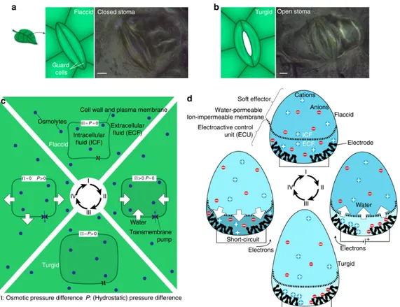
Figure 2.5 The explanation of reversible actuation mechanism in plants based on osmosis. The tendril-like structures in plants function to design an actuator based on osmosis. Schematic representation and optical images of Tradescantia Zebrina leaves showing two stages (a) close (turgid) (b) open (flaccid), of the stoma cells. Scale bars: 10 µm. (c) and (d) cyclic osmoregulation (c) for plant cell and (d) for an artificial osmotic actuator that is designed taking inspiration from (c).[36]
Plants actuate their body and extremities by manipulating the amount of water in their cells. Changes in the local osmotic pressure, which cause an internal pressure (turgor pressure) in the plant cells, are effected by the movement of water due to the electrolyte concentration difference of the two transport boundaries [42][35]. These differences form a gradient in stiffness throughout the plant body, which continuously changes upon growth or depending upon the external stimuli. This results in a
‘controlled’ bending of the plant body. Recently, it has been shown that osmotic actuation can used in soft robotics, in a biomimetic reversible manner [36].
2.2.2 Artificial Heliotropism and Nyctinasty
Ability to track the sun (heliotropism) and rapidly open and close the leaves upon illumination (Nyctinasty) are two of the most fascinating features of plants. In heliotropism, the controlled diurnal motion is achieved by biochemical feedback as a result of the changes in turgor pressure, which causes a movement in the motor cells [35], [36]. Heliotropism helps the plant leaves to receive the incident solar light at angles close to 90o with the leave surface, through which plants maximize the solar
input [2], [43], [44].
Figure 2.6 a) Solar tracking (heliotropism) of plants. Photo taken from [29], which also shows b) the of rate of CO2 production by a heliotropic plant (pinus arizonicus) vs a
non-heliotropic one.
Below, examples of artificial plants displaying artificial heliotropism and nyctinasty will be displayed. These plants, too, will use a feedback mechanism, similar to real plants in performing these motions.
12
Chapter 3
3. The Next Episode of Soft Robotics: Embodied Intelligence
The next episode of soft robotics, autonomous robotic systems, not tethered to the hard controller and power source, are inspired from nature (living organisms) for adaptability to complex tasks. Soft robots are emancipating themselves from their tethers by the implementation of autonomy [2], [4], [10]. Self-regulation through materials feedback (similar to biochemical feedback found in nature) is one way to achieve that goal (Figure 4.7 and 3.1). Despite the recent studies showing bioinspired self-healing [45] and other materials and synthetic systems using chemical feedback or self-regulation, materials feedback have not been accomplished in a robotics system except in our recent study on artificial heliotropism and nyctinasty in plant robots with material feedback.
Figure 3.1 The solar trackers benefitting from material feedback to track the sun autonomously. The left photo is of a computer controller solar tracker; the photo on the middle is a plant robot tracking the position of the sun through material feedback [2], and the right one is of an artificial plant operated by artificial transpiration tracking the position of the light source. [2], [46]
14
Chapter 4
4. Results & Discussion
4.1 Artificial Heliotropism and Nyctinasty
In order to make a functional, adaptive, and self-regulating autonomous plant robot, we had first started with the following setup for a ‘proof-of-principle’ of artificial heliotropism and nyctinasty displayed by an artificial plant robot, Figures 4.1-4.4. Then we changed our experimental design in order to accommodate biomimetics; i.e. to have a tracking feedback through artificial transpiration, Figure 4.7-4.9. Although the movement and duty performed by these two systems are similar, there are two main differences between them; 1) the working principle of the tracking feedback (material feedback vs. artificial transpiration), 2) and the level of bio-inspiration – the second setup also mimics the metabolic activities of the real plants in achieving the heliotropic motion.
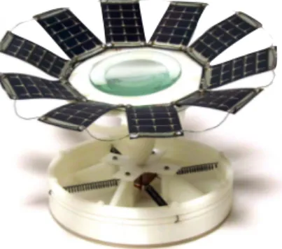
Figure 4.1 The plant robots performing heliotropism and nyctinasty. (a) Photographs of the heliotropism only system the left (in the dark) and the right (optimizing the solar input by turning toward the source of light). (b) Photographs of the plant robot performing both heliotropism and nyctinasty. The images on the left are in the dark, the plant robot is in its initial state, leaves are closed. The images on the right are under the illumination of light source form a certain (approximately 60O) angle with
the leaves open and the crown turned towards the source of light. Both systems are made out of a 3D printed plastic body with properly positioned nitinol springs, lenses on top of the crown, and solar panels as its leaves, as also shown in Figure 5.1
4.1.1 The Plant Robot with Hard Elements: The-Proof-of-Principle
16
In the first part of this work, we demonstrated heliotropism and nyctinasty in a self-regulating system with no electronics (Figure 4.1). The autonomy in heliotropism and nyctinasty in this system relied on an integrated opto-/thermo-mechanical feedback, which mimics the diurnal motion plants. Using few smartly placed lenses and nitinol (NiTi) springs, our plant robot was able to open its petals (solar panels) upon light exposure (nyctinasty) and can track the sun (heliotropism) or a light source (phototropism) until the feedback mechanism stabilizes the solar panels for the optimal solar input in a non-equilibrium state. (Figure 4.4). (This feedback mechanism will be described in the next section, 4.1.1.1 in detail.) This system successfully showed how material feedback can be integrated into a robotics system. It was tested for efficient solar tracking (Figure 4.6). In addition, the energy harvested by the solar panels in the system was also used to charge a capacitor. Like the real plants - the masters of energy storage as well as the efficiency – the artificial plant performed these tasks successfully to maximize the energy harvesting and storage (see Experimental Section, Figure 5.3). The field tests showed that our plant robot increases the efficiency of light-harvesting by 30–110% (depending on the elevation of the sun) compared to the static, non-heliotropic system (at 90O elevation angle), stored this energy in an external capacitor
(see Experimental Section Figure 5.3). This design shown lowered the energy consumption by eliminating electronics (w/o the use of any power-consuming actuators or controllers) and increased the energy harvested by the solar panels by tracking the sun [2]. In addition to a successful display of the use of material feedback in robotic systems; with this design we have shown that inexpensive, robust, and completely autonomous solar trackers can be produced. This concept may be developed for solar trackers used especially in harsh environments like in deserts and space, where
sustainability of delicate electronics and computer-controlled solar trackers might be a challenge. In the next sections, the working principle, the feedback mechanism and the field performance of this plant robot are described in detail.
4.1.1.1 How Material Feedback is used to Build The First of Autonomous
Plant Robot
As we have described above feedback loops are one of the essential components of living systems[25]. But, embedding them into material-based systems without any electronics has been a challenge[14]. There are some examples of these systems, but none of them achieved move a macroscopic object. In our journey of finding proper material to accomplish a directional motion upon illumination of light -among shape memory polymers, pressure-driven systems, and light-induced deformations of polymers- we found that shape memory alloys (Nickel-Titanium, NiTi alloys) are proper candidates due to the large force they can exert, their durability and reversibility. NiTi alloys, namely nitinol, is a well-known shape-memory alloy composed of Ni and Ti, has an improved resistance to fatigue, and can operate by reversible solid-state phase transformation between two different martensite crystal phases (see Experimental Section Figure 5.1b).
We started our initial design with the heliotropism-only system. The structure is shown in Figure 4.3 and 4.5 consists of a 3D printed crown (moveable) and a stem (stationary) both connected and upper body supported with nitinol springs (see Experimental Section Figure 5.1). These springs are made of a ∼2 mm thick nitinol wire, are ∼6 mm in diameter, and have 11 turns per 2 cm length (total length in the constricted form). Two convex lenses are placed on the crown, one on top of the other (lens diameters 75 and 50 mm, respectively, ∼10 cm focal length for each lens, see Experimental Section
18
Figure 5.2-5.2). The crown is surrounded by 8–10 solar panels (Flexible Solar Panel MP3-37, MP3-25, or SP3-37 from Powerfilm) serving as “leaves” harvesting the energy of sunlight. Each solar panel can generate 4.5–4.8 V, and when the panels are connected in parallel, they give a maximum current of 180–250 mA depending on the intensity of the incident light (Figure 4.3 and 5.3).
Figure 4.3 The schemes and images of heliotropism-only plant robot. (a) and (b) The lens in the design (Figure 5.1 and 5.2) focuses the light directly on the nitinol springs Local heating and contraction (regions heated by focused light are denoted by red asterisks) bends the crown towards the light source. The left column is for the high elevations of the sun – the spring is heated from its middle region (denoted xm) to the
innermost region xi, resulting in a small contraction and bent of the crown. Whereas,
with the low elevations of the sun, heating starts near the spring's outermost region, xO. The spring contracts more, so the crown is bent further to lower degree angles. The
insets are the optical and thermal images of the springs being contracted. (c) the response of the system upon the illumination by a light source (IR lamp, 250 W, General Electric). The bending motion is completed within 2.5 min and reverting back to initial position, which takes place when the light is turned off, takes 2 min.
The sizes of the crown and the stem are optimized in a way that the lenses focus the light onto the nitinol springs, causing local heating and contraction depending on the position of the light source. Figure 4.3 illustrates the response of the system to run at two different elevations. When the light source (sun in this case) is high (left), the initial position of the crown is straight (90O form the ground), and the focal point is
falling close to the center of one of the springs, designated as xm in Figure 4.3. As the
illuminated part of the spring is heated and contracted, the crown bents toward the light source while the focal point moves in harmony resulting in contraction of portions of the spring between xm and the innermost region xi. Whereas, when the light source
is at low elevation angles (the right), the focus of the light is at the spring's outer region, xo. This time the spring is heated and gradually contracted over its entire
extent, from xo to xi, resulting in more bending than high sun elevation. Of course,
there are many situations between the two illustrated limits. The bending angles of heliotropic motion depend on the position of the light source. However, without a feedback the stem would bend until the nitinol wire is completely contracted, and this would not allow a true heliotropic behavior. The feedback is achieved; as the plant stem moves, the lenses also move together with it and the projection of the light on
20
the nitinol wire shrinks to a smaller spot. The previously heated sections cool as the light moves away from them and re-expand. Therefore, the plant stem moves ‘back’. However, when the stem moves back, the light coming through the lenses now project a larger spot on the springs and heats and contracts this higher number of spring turns, making the plant bend again. This slight back-and-forth movements are utterly controlled by the elevation of the sun and how the spot sizes changes according to it. The overall observation is that the “plant” is always stabilized in a non-equilibrium, dissipative state, in which it faces the light source and tracks it continuously (Figure 4.4). We note that any overheating and extreme bending is also self-regulated by the system. (Figure 4.3c).
Figure 4.4 The optomechanical feedback stabilizing the plant in the position of maximizing solar flux. When spring denoted as “1” is heated by the sunbeam focused through the lens, it contracts and the stem turns toward the sun until the steady-state position is reached. Any additional overturning is prohibited since the beam is then focused between the two springs, or onto spring “2,” in both cases causing retraction of the stem. These two situations are illustrated by the experimental images in the bottom row. Red asterisks give the position of the focal point.
To cover a wider range of azimuthal angles, to the final design, more number of radially directed springs were added (see Experimental Section Figure 5.1-5.5). The feedback works on each of these springs as described above, for one spring. We should also note that the actuation and the feedback achieved by the nitinol spring contraction and expansion can indeed be fast; the changes in the temperature of the springs upon illumination are not small (ca. 20°C, see thermal-camera images in Figure 4.3) causing a response of NiTi (10–20 s), and a rapid heliotropism (compared to those of living plants), which occurs on a time scale of 1–2 min (Figure 4.5 and 4.3c).
Figure 4.5 Device capable of both nyctinasty and heliotropism. (a) Scheme of the “plant” exhibiting nyctinastic (NN) and heliotropic (HT) motions simultaneously. Upon light exposure, four nitinol wires at the top of the “crown” contract such that 16 solar panel leaves open up exposing the inner lens that can then control heliotropic motions. Both nyctinasty and heliotropism cease, when the light is turned off, and the device returns to the initial state. The experimental images (b) upon irradiation with IR lamp, 250 W, General Electric; (c) of the plant's response when light is turned off.
22
Finally, we showed a plant robot performing both heliotropism and nyctinasty. In addition to the previous heliotropic system described above, a sensory ‘pistil’ consisting of four more nitinol springs was placed on top of the crown. These were connected to the solar panels “petals” (Figure 4.5 and Figure 5.4). When the light is turned on, the pistil springs are heated and contracted within 2–3 min, the plant robot reveals its solar panels and its lens (Figure 4.5b). Now, the device is able to perform the material feedback controlled heliotropism (or phototropism, if it is working indoors) as already described above for the heliotropic plant. When the light is turned off, the crown and pistil go back to the initial metastable state, while the leaves close up as illustrated in Figure 4.5c.
4.1.1.2 Performance Characteristics
The field performance of the plant robot was performed in Ankara, Turkey on both warm (ca. 30OC and cold (ca. 10OC) sunny days. The plant robot completed its diurnal
cycle under sunlight. In these cycles, the solar panel functioned as ‘leaves’ and harvested the energy of the sunlight. As expected, heliotropism increased energy efficiency, a 30-110% increase -depending on the position of the sun - was recorded. The highest efficiency increase (compared to the non-heliotropic system) was observed in the morning and in the evening hours, when the sunlight beams were hitting on earth with lower degree elevation angles. The efficiency increase was quantified by the power generated by the solar panels (Figure 4.6) and by the potential accumulated by a capacitor connected to the panels (Figure 5.3). The capacitor charging experiments also showed that the energy collected by the autonomous plant robot can be stored as plants in nature store energy in the forms of carbohydrates, fats, and proteins.
Figure 4.6 Field performance of the plant robots on a typical summer day in Ankara, Turkey. (a) The initial state of the plant robot. (b) Heliotropism of the plant robot in the morning hours (under the low elevated sun). (c) The elevation angle of the sun, α. (d) Current generated by the solar panels connected parallel as a function of the day time (from 9 AM to 5 PM), for the heliotropic plant robot (red circle markers), and for the non-heliotropic reference robot in which the crown is stationary (blue square markers). (e) The percentage improvement in power generation for the heliotropic device versus the non-heliotropic, immobile stem control (based on the data from (d)). Power enhancement is up to 110% when the sun is low and bending of the stem is essential to capture any appreciable flux of photons. (f) The elevation angle of the artificial light source used indoor, α. (g, h) A similar comparison (heliotropic vs. non-heliotropic design) as in d and e, but based on the ability to load a capacitor connected
24
to the solar panels of the “plant” (for the wiring scheme and further details, see Experimental Section. (In (g), Red circle markers = heliotropic plant, blue square markers = non-heliotropic plant.)
4.1.2. Paper Plant Robot (PPR)
Scientists and engineers were inspired by the plant texture, architecture, and function for many centuries the plant tissues display interesting surface texture and physics. Although plants are immobile, unique movement patterns in plants, tropism (slow, gradual moving towards or away external stimulus) and nasty (fast motion), have also attracted attention of many. As was shown above we, too, were inspired by these motions and have shown that artificial functional systems can be constructed, imitating these motion[2]. Plants also have very sophisticated mechanisms in their biological metabolism. The transport of water from the roots to the stem and the leaves is one of them.[2], [29], [39], [18], [47]. Although the initial design we described in [2] successfully performed both of these movements, it failed to be biomimetic because it did not mimic the biological mechanism of them, which is governed by the water transport and changes in the turgor pressure in the plant body. The previous design also involved only hard components, which prevent it from being referred to as a ‘soft’ robot.
Figure 4.7 Bio-inspiration and incorporation of embodied intelligence in paper plant robots (PPR). (a) Living systems (plants) are operated by embodied intelligence achieved by biochemical feedback. Embodied intelligence in PPR are attained by material feedback in a similar way (b) Properly placed hydrogels on origami PPR allows the system to have material feedback. The left column is the initial ‘dark’ state of the PPR with its leaves closed. The right column is the final (metastable) state of the PPR upon the illumination of light with its leaves open (nyctinasty) and bent towards the light (heliotropism). The PPR stays at the metastable state as long as the external stimuli, the light is on. When the PPR is connected to a water source or hydrated by a spray of water intermittently, both motions are regulated autonomously
26
through material feedback (Figure 5.11). (c) A field of PPR is showing a gradient of responses depending on their position with respect to the light source; displaying agile, continuous action (as expected from ‘soft’ robots) controlled by the intensity of the light stimulus. Scale bars are 1 cm.
In this study we show, the evolution of plant robots from hard to soft, while still having a successful self-regulation of heliotropism and nyctinasty. Moreover, the new, paper based, soft system is not only self-regulating and bio-inspired but biomimetic as well: It is able to employ ‘artificial’ transpiration to achieve heliotropism and nytinasty similar to plants in nature.
4.1.2.1 Transpiration
Transpiration – the most commonly used water transport mechanism by the largest living mass, plants – is the water transport from the roots to the aerial parts (e.g. leaves) of the plants. Plants use transpiration not only to regulate their temperature and the osmotic pressure in the plant cells but to transport the nutrients and minerals dissolved in water. Transpiration occurs via the difference in chemical potential of water in the various parts of plants with the main driving force of capillary action and evaporation. It is regulated by biological, non-equilibrium feedback. The overall picture of transpiration is that the water is continuously sucked from the roots depending on the evaporation from the leaves (the amount of water transpired may reach tons per day!). Similarly, we built our PPR system based on the balance between the capillary action and evaporation. In the next section, choice of materials and mode of operation will be explained in details.
Despite the other candidates to integrate a feedback mechanism to our PPRs like chemical reactions, we choose simple transport of water (by swelling/deswelling of hydrogels) since; 1) water is the simplest and the ideal substrate for metabolism and diurnal motion namely life of plants, 2) many tropism and nastic movements (such as light, heat, chemicals, humidity, gravity, electric field, temperature, or touch) are performed by the change in turgor pressure of the plant cells which allows us to design more functional and complex system in future.
4.1.2.2 Choice of Materials
The balance between evaporation and capillary action in plants was the main inspiration of our design of ‘artificial’ transpiration. We simplified the complex biochemical feedback loops that also takes place in plants into a non-equilibrium of evaporation and capillary action on the PPR body. In nature, plants are changing the turgor pressure of their cells, changes the size of the cells so the plant moves. We use a very similar idea by simply changing the size of our corresponding hydrogels to obtain a very similar movement pattern performed by the plants.
In our earlier designs, we divided artificial transpiration into two, evaporation and capillary action. First, our goal was to construct an evaporation-only plant robot performing heliotropism, which worked efficiently as shown in Figure 4.7-4.9. In the beginning, we had tried 3D printed acrylonitrile butadiene styrene (ABS) and polystyrene robot bodies. Although those systems were promising, we decided to switch into a simple and more efficient (capable of performing capillary action) material that is paper – as the plants are also using capillary structures (for transpiration) and mechanical strength (for robust, durable structures) of cellulose/lignin composite
28
networks. Using paper is not only advantageous as it is a natural, biodegradable, easily available material but also it provides straightforward manufacture through cutting/engraving (one can fabricate a paper plant robot even only with scissors!). This easy-to-prepare folding structure enables us to utilize origami and kirigami strategies into our design for more complex functions (e.g. auxetic behaviors, continuum motion or single input – multiple output systems) that would have required thousands of lines of codes in conventional methods. Although many similar types of paper can be used to obtain similar results, we preferred especially this type of thick, durable cellulose paper (Canson 1557-200g/m2, for details of the design and production, Figure 5.6) to engrave the crease patterns, which many reversible cycles of operation without any loss of reversibility. For the capillary action, we choose simple, general use filter paper to transport water from the ‘roots’ to the hydrogels. For the hydrogel selection, we tried common hydrogels have potential to serve as an actuator. In many examples in literature (e.g. agarose, gelatin, polyacrylamide, and thermoresponsive poly(N-isopropyl acrylamide), we found agarose to be the best for this duty due to its structural integrity (within itself and together with paper), and reversibility at hydration/dehydration cycles. It is natural, biodegradable, cheap, easy-to-prepare material that has never been used in robotics before. With these materials (as simple as paper, water, and agarose/a polysaccharide) and manufacturing methods (Origami and Kirigami), our plant robot can display heliotropism and nyctinasty, can be manufactured within several minutes from these everyday materials. Such a ‘plant garden’ like in Figure 4.7c, can be obtained in about 10 mins – in which many plants simultaneously operate upon a single light input (Figure 4.7). This is system is a perfect example of how powerful simplicity is to have a system can perform such complex movement patterns.
![Figure 2.2 The left column is an octopus the source of inspiration, the right column is a bio-inspired soft robot.[4]](https://thumb-eu.123doks.com/thumbv2/9libnet/5614399.111027/26.918.279.729.188.365/figure-column-octopus-source-inspiration-right-column-inspired.webp)