www.gujs.org
Determination of the Strength of Various Sofa Frames
with Finite Element Analysis
Ali KASAL
*Muğla University, Faculty of Technical Education, Department of Furniture and Decoration Education, Kötekli,48000, Muğla, TURKEY Received: 15.02.2005 Accepted: 10.10.2006
ABSTRACT
In this study, the strength properties of glued-dowel joined sofa frames constructed of solid wood and wood based composite materials were investigated. Furthermore, the place of the stretcher was optimized in the side frame of the sofa. Scotch pine (Pinus Sylvestrıs Lipsky) and Turkish beech (Fagus Orientalis Lipsky) were used as solid wood materials. Oriented strandboard (OSB), okoume (Aucoumea klaineana pierre) plywood (PLY) and medium density fiberboard (MDF) were used as wood composites. Specimens were tested under static load according to the principles of TS 9215 by applying both seat and backrest loads which the sofa can be imposed upon in service. The finite element method was utilized for analyzing the sofa frames. As a result, it has been observed that the three dimensional structural analysis by means of the finite element method gives reasonable estimates of the overall strength performances of the sofa frames. Furthermore; it was concluded that the wood composite materials could be used instead of solid wood materials in the production of the frame construction furniture, especially in the upholstered seating furniture frames.
Key Words: Frame construction, strength design of furniture, wood composite, finite element method, structural
analysis.
*Corresponding author; e-mail: [email protected] 1. INTRODUCTION
Today, the world population is increasing rapidly. Furniture demand by the customers has developed parallel to this situation. Gradually, decreasing of the forest resources requires more efficient use of wood materials in frame furniture production and better proofing of the furniture to ensure its durability. Within this scope, a number of appropriate performance test methods have been developed for furniture by bringing up the concep of furniture engineering [1].
Today, strength (engineering) design of furniture can be accomplished by utilizing solid modeling and structural analysis softwares. All members of the product can be modeled parametrically and required changes can readily be optimized via advantages that are provided by the solid modeling. Likewise, strength calculations of the designed product could be made by means of the computer aided structural analysis software [2]. When the recent studies have been investigated, it has been seen that the software, especially finite element method (FEM) have been commonly utilized in structural analysis of the furniture systems.
Efe at all (2003) constructed two school chairs with cylindrical mortise and tenon joints, and these were tested utilizing the “cyclic stepped increasing load method”, and the specimens were structurally analyzed by means of FEM software. As a result, they determined that three dimensional structural analyses by means of FEM provided reasonable estimates of the overall strength of the frame furniture [3].
Cai at all (1995) analyzed that the strength and stiffness of the moltinject corner joints of cabinet furniture by comparison with that of two pin dowels corner joints. Furthermore, the deflection of cabinet furniture whose corners were joined by the method of moltinject was predicted reasonably in this study using FEM calculations [4].
Gustafsson (1995); emphasized that, because of the much more common use of computers and developing technology, it is possible to use modern finite element programs in various stages of the design process. For this purpose, he structurally analyzed a simple chair by utilizing the finite element method [5]. Gustafsson
(1996), in his similar study prepared a simple birch chair and tested its strength under various loads which the chair could be imposed upon in service. Furthermore, he determined stresses at various nodes with the finite element method by modeling the chair. He has pointed out that the test results and data analyses were reasonably coherent with each other [6]. In his other study, Gustafsson showed how to analyze and design a chair with finite element method, and gave stress diagrams and test results of prepared real size ash wood chair [7].
Smardzewski (1998) carried out a research project for developing a computer program designed for rigidity/strength analysis of furniture side frames. Afterwards, he analyzed a side frame of a chair, and demonstrated that the computer program developed allows accurate, rapid, and multiple rigidity strength analysis of furniture side frames constructed of wood [8]. Smardzewski (2002), in another study, developed a mathematical model describing phenomena occurring in bent mortise joints prevalent in constructions of skeleton furniture, but also tried to determine factors influencing the strength of glued mortise and tenon joints. Analyses were treated with a computer assisted program prepared and developed at the Poznan Agricultural University. According to obtained results; shear strength of the glue utilized and compression strength of wood which the joints were constructed from affected the bending strength of glued mortise and tenon joints. Furthermore, it was mentioned that when well fitted members of the mortise and tenon joint, compressing one another was provided, stresses in the glue bond reduce and increase its strength [9].
Daudeville at all (1999) analyzed the static load bearing-capacity of bolted timber joints experimentally and numerically; and investigated the influences of different structural parameters such as the dowel diameter and sectional sizes of the members on the strength. They utilized from the finite element method in the framework of “linear elastic fracture mechanics” via the computer aided theoretical analysis. The comparison between experimental and numerical results showed that the finite element method must be considered for a correct prediction of the ultimate load performance of bolted timber joints [10].
Nicholls and Crisan (2002) analyzed the stress and strain states in doweled and minifix type corner joints of the case furniture by using the finite element method. As a result, they have stated that the stress concentration areas in the models are developed as in the physical joints, and the stress-strain state in the corner joints can be accurately predicted.
Erdil (2001) tested and analyzed various types and sizes of wood chairs and desks based on the conventional structural design method, and evaluated the furniture by performance test equipment and procedures selected specifically for that purpose. As a result; he obtained the
optimum sizes, and stated that the performance test method and test equipments were appropriate, furthermore structural analysis by means of finite element method provide reasonable estimates of the overall strength of the furniture [10].
The purpose of this study was comparing the load bearing capacity of glued doweled sofa frames constructed of solid wood and wood composites, and analyzing the strength of sofa frames. Furthermore, computer aided three dimensional structural analyses of the specimens were done by using the finite element method and the obtained data was compared with the actual test data. As a result, it is aimed to provide information about the possibility of the use of three dimensional structural analyses via finite element methods in the product engineering of furniture.
2. MATERIAL AND METHOD 2.1. Wooden Materials
In the tests; first grade Turkish beech (Fagus Orientalis Lipsky) and Scotch pine (Pinus Sylvestris Lipsky) were used as solid wood materials which are commonly used in the furniture industry of Turkey. Lumbers have been obtained from commercial suppliers by simple randomly selection method. Okoume (Aucoumea klaineana) plywood (PLY) according to TS 46, medium density fiberboard (MDF) according to TS 64, and oriented strandboard (OSB) produced according to the principles of EN 300 which are 18 mm thick were used as wood composites [13, 14, 15].
Some required physical and mechanical properties for structural analysis of the wood and wood composite materials used in the tests were evaluated in accordance with the procedures described in ASTM D 1037 [16] standard. Before the tests, specimens were kept for one month in an environment chamber that was set to conditions of 20 ± 2 °C temperature and 65 ±5 percent relative humidity (r = %12).
2.2. Adhesive
In the tests, polyvinyl acetate adhesive was utilized because of its useful properties such as cold application, easy spreading, rapid drying, being scentless and fireproof, and being preferred in the production of the sofa frames. Some properties of the adhesive utilized were given by the producer firm as density of 1,1 g/cm3, viscosity of 160-200 cps, PH = 5.00, ash rate of 3 % [17].
2.3. Preparation of the Specimens
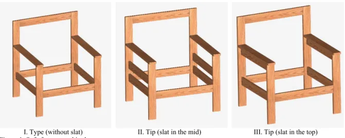
Based on the foundations of the TS 9024 (18), a total of 45 sofa frames were prepared in 1/1 scale (Figure 1). For this purpose, members of the frames were cut in their final sizes by processing in jointer, planer and circular saw (Table 1).
I. Type (without slat) II. Tip (slat in the mid) III. Tip (slat in the top) Figure 1. Sofa frames used in the tests
Table 1. Final measurements of the members of sofa frames (mm)
Member Length Width Thickness
Stump 532 70 18 Back post 800 70 18 Arm 602 70 18 Side rail 564 70 18 Side slat 564 70 18 Front rail 550 70 18 Back rail 550 70 18 Top rail 550 70 18
Since the wood composites were 18 mm thick and their surfaces were smooth, they were cut directly in final length and width on a circular saw.
In the joints, grooved beech dowels were utilized according to principles of TS 4539 (19), and the diameter of the dowels was 8 mm while the length of the dowels was 40 mm. Horizontal and vertical drill presses were utilized for the dowel holes. Dowel hole centers were drilled at a point 16 mm from the edges symmetrically, and to the center of the thickness of the members from the faces. The distance between centerlines of two dowels was 38 mm. The depth of the embedment of the dowels in the edge was 27 mm, and the depth of the embedment of the dowels in the face was 13 mm. In the other words, penetration of the dowels was 13 mm.
Assembling procedure of the sofa frames were performed in two phases. The side frames of the sofa were constructed first (sub-assembly); afterwards, the side frames were combined to the front, back, and top rails and assembly of the whole sofa frames were constituted. In the gluing process, glue was spread over the dowels and intersection surfaces, approximately with 150±10 g/m2. In the pressing process, the sofa
frames were maintained for 2 hours by applying pressure to the joints.
All sofa frames were stored in a chamber with the conditions of temperature of 20 ± 2 °C and relative humidity of 65 ±5 percent for two months. Measurements of the gravities were made with an analytic weighing machine with a sensitivity of 0,01. The principles of TS 2471 (20) were fulfilled for calculating of the moisture content.
In the study, a total of 45 sofa frames which included 5 material types (2 types of solid woods and 3 types of wood composites), 3 side frame types, and 3 replications for each specimen were constructed and tested.
2.4. Performance Tests
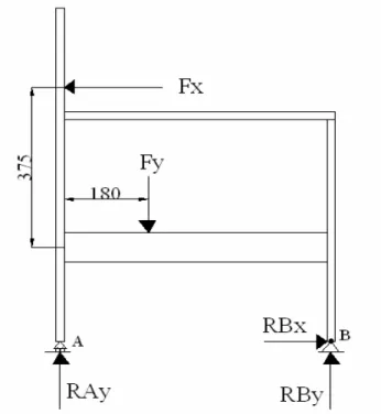
Tests were carried out on a 30 kN capacity “Seidner Bending Machine”. Static loading rate was adjusted to 6 mm/min (2). Sofa frames were tested according to the principles of TS 9215 [21] and ISO/DIS 7174/1 [22] by applying both seat and backrest loads which the sofa can be imposed upon in service (Figure 2).
Figure 2. Applying the seat and backrest loads
Seat load (Fy), a constant value of 85 kgf (833 N), was applied to the sofa, backrest loading (Fx) was continued from the coordinate points as shown in Figure 2 until a failure or full separation occurred in the joints or members of sofa frame. In the tests, the ultimate failure loads were recorded in Newton (N).
2.5. Computer Aided Three Dimensional Structural Analyses
Computer aided analyses were carried out with RISA– 3D [23] that is commercially available finite element analysis software. In the analyses, all sofa frames were treated as three–dimensional frames, as in reality. In accordance with their groups, the typical procedure used in the structural analysis of each sofa frame was as follows;
a. General Settings (Global)
- Adjusting of the unit systems (Units)
- Adjusting of the number of sections to be separated for each member (Section)
- Adjusting of the coordinate system
(Coordinates)
b. Modeling Phase (Modeling)
- Adjusting of the drawing limits and scale (Drawing Grid)
- Three dimensional modeling of the specimens in 1/1 scale (Drawing)
- Attaching of the members to each other and integrating of the system (Merge)
- Make a file from the drawing (File) c. Description of the Materials (Materials)
- Inserting the technological properties of the materials used (General Material Properties) d. Description of the Members (Members)
- Inserting the sectional properties of the members (Member Section Sets)
e. Definition of Attributes to the Members (Information for members)
- Definition of the materials and sectional properties of each member (Members, Sections)
- Creating members and nodes (Node) f. Solution (Solve)
- Determination of the supports and their types (Boundary Conditions)
- Applying the test loads from the nodes (Joint Loads)
- Solution of the system (Solve) g. Output of the Results (Results)
- Taking of the reaction forces (Joint Reactions)
- Taking of forces and moments which act on the members (Member Forces)
- Taking of stresses which occur on the members (Member Stresses)
- Taking of the deflections of nodes (Joint Deflections)
- Drawing of the normal force, shear force and moment diagrams (Member Deflection Diagrams)
- Drawing of the deflected shape of the system (Deflected Shape).
In the general settings part, the unit system was adjusted as standard metric, and considering the SI (standard international) units. Each member that integrates the system was divided into five equal sections for analyzing the forces acted and drawing the diagrams. The coordinate system was adjusted as the (Y) axis in
-l...ııF
x
1 ....f
F
y
1 QO"I,
-RB
x
~
-' ~ A ".:L ~ B.~
.~
RAy
RB
y
vertical position, the (X) axis in horizontal position, and the (Z) axis in depth position.
In the modeling phase, firstly the drawing limits were adjusted in sufficient sizes for modeling the three dimensions of the sofa frames. Later, sofa frames were
modeled as three dimensional. Each member of the sofa frame was drawn individually, and then attached (merged) to each other, so the frame system was integrated. A special file was made for each group. A code was given to each joint by the program during the merging of the files (Figure 3).
I. Type II. Type III. Type
Figure 3. Nodes of the sofa frames tested (D1, D2,D3, D4, D5, D6, D7,...D18: Member nodes and / or supports). In the description of the materials, some technological
properties of the materials utilized for the construction
of the sofa frames entered into the program were given in Table 2 [2, 24].
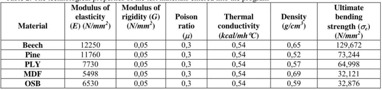
Table 2. The technological properties of the test materials entered into the program
Material Modulus of elasticity (E) (N/mm2) Modulus of rigidity (G) (N/mm2) Poison ratio (µ) Thermal conductivity (kcal/mh°C) Density (g/cm3) Ultimate bending strength (σe) (N/mm2) Beech 12250 0,05 0,3 0,54 0,65 129,672 Pine 11760 0,05 0,3 0,54 0,52 73,244 PLY 7730 0,05 0,3 0,54 0,57 64,998 MDF 5498 0,05 0,3 0,54 0,69 32,121 OSB 6530 0,05 0,3 0,54 0,59 32,876
In the description of the materials, the sectional properties of the members that integrate the furniture system were entered into the program. These properties are cross sectional area, moment of inertia around (Y)
and (Z) axes, form constants for shearing stresses and torsional constant values. The formula of [2.1] was utilized for calculating the torsional constant values of the members which were in rectangular sections [25].
Jd = (U/2 x (K/2)3 ) x ((16/3)–3.36 x ((K/2) / (U/2)) x (1–((K/2)4 / (12 x (U/2)4 )))) (2.1)
Jd : Torsional constant for rectangular sections (mm4)
U : Width of the section (mm) K : Thickness of the section (mm)
The members of the sofa frame, which were in vertical position, have been called “arm type”, and the members which were in horizontal position have been called “rail type”. Cross sections of all the members were the same, but their orientations were different resulting in different inertial values according to the three dimensional system. The sectional properties of these members were given in Table 3. Each member of the
sofa frames were given a code by the structural analysis program for easily evaluating the data from the result outputs (Figure 4). In the part of definition of attributes to the members, all of the properties of the members and sections entered into the program until now were defined for each member, individually.
Table 3. The members of the sofa frames and their sectional properties
-~ N N N nı• 00 nı, ,oo ,oo ,ooMember Type Cross sectional area (mm2) Moment of inertia (Izz) (mm4) Moment of inertia (Iyy) (mm4) Form constant for shearing (SAy) (SAz) Torsional constant (J) (mm4)
Rail type (vertical) 1260 514500 34020 1,5 114043
Arm type (horizontal) 1260 34020 514500 1,5 114043
I. Type II. Type III. Type
Figure 4. Member codes of the sofa frames (E1, E2,E3, E4, E5, E6, E7, E8, E9, E10, E11... E27 : Members of the system)
In the solution phase, firstly the support types (degrees of freedom constraints) of the points which touch the floor was determined. As the actual tests, the stump was supported as pin (pin support), and the back post was supported as roller (roller support) to the floor. There are six degrees of freedom at each joint (node). In other words, all joints can carry the axial forces, shear forces, and the bending moments.
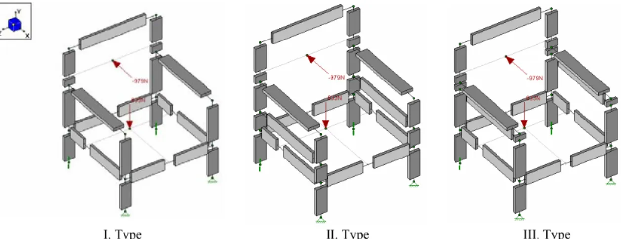
After the supporting, the solution of the system was made by applying the maximum load levels achieved during the performance tests from the points in the actual tests at the nodes in the model. In the given figure, the members that integrate the system were shown in 3/4 render to easily show the joints. For this reason, they have been showed 1/4 shorter than the real sizes (Figure 5).
I. Type II. Type III. Type
Figure 5. Applying the test loads to the sofa frames in the computer program In the solution part, reaction forces, axial forces, shear
forces, and bending moments acting on each member, the stress values that occur along the materials of the solved systems were taken from the program.
Furthermore, normal force, shear force, and the moment diagrams were drawn by the program.
2.6. Evaluation of the Data
Effects of the material types, side frame types, and interactions of material type side frame type on the load bearing capacity of the sofa frames were determined by “analysis of variance” (ANOVA). If the differences have been found statistically significant according to p<0,05, the “least significant difference” (LSD) test was performed for the importance of the differences between the groups.
The computer aided three dimensional structural analyses was made by using the finite element method (FEM) under the actual test conditions and loads.
3. RESULTS AND DISCUSSION
3.1. Some Technical Properties of the Materials Used
Some physical and mechanical properties of the materials utilized for constructing the sofa frames were tested and given in Table 4.
Table 4. Some physical and mechanicl properties of the materials
Material type Moisture content (%) Density (g/cm3) Tension strength (N/mm2) Compression strength (N/mm2) Shear strength (N/mm2) Bending strength (N/mm2) Modulus of elasticity (N/mm2) Beech 10,2 0,65 128,5 79,1 10,3 129,6 12250 Pine 11,2 0,52 73,7 49,7 6,2 73,2 11760 vertical 60,2 3413 PLY horizontal 9,1 0,57 39,7 37,8 8,9 64,9 7730 vertical 24,7 2290 MDF horizontal 7,1 0,69 15,6 18,7 5,5 32,1 5498 vertical 19,4 2450 OSB horizontal 7,6 0,59 10,9 16,6 5,6 32,8 6530
3.2. Deformation Characteristics of the Joints
Complete failures occurred between 30-60 seconds. During the failure, a sound was heard and openings occured in a short time in the joints. Opening failures started at the edge of joint section and then propagated towards to top of the joint with increasing load for the joints. Dowels were not broken. In the sofa frames constructed of PLY, delaminations occurred in the layers of the plywood, and in the sofa frames constructed of OSB, failure was the pull-out of dowels from the member with some core wood particles attached to the dowel. Some splits occurred at the edge of the butt members in the sofa frames constructed of MDF and OSB.
Although the intersection surfaces of the joints are coated with glue, the contribution of the bonding ensured in the mentioned area is not primarily important for the joints, therefore for the whole system because these surfaces are cross section in the solid wood materials, and edge section in the wood composite materials. The rigidity of the system was essentially provided by the dowels and bonding around the dowel surfaces. Normal (axial) stresses occurred at the glue line in the intersection surfaces. In the bonding around the dowel surfaces, the shear strength of the PVAc glue used become important. When shear stresses in the mentioned area excees the shear design stress value, the joints become deformed.
3.3. Performance of the Sofa Frames
Load bearing capacity values of the sofa frames obtained from the strength tests were given in Table 5. The analysis of variance concerning the effects of material type, side frame type and material type-side frame type interactions on the performance of the sofa frames were given in Table 6.
According to the results of the variance analysis, effects of the material type, side frame type and material type-side frame type interactions on the load bearing capacity values of the sofa frames were found to be significant at the level of 0,05.
The means comparison in relation to effects of the material types on the load bearing capacity values of the sofa frames for LSD critical value of 103 N were given in Table 7.
According to results of the comparisons, success orderings were obtained as follows; beech, PLY, pine, MDF, and OSB, among the material types.
The situation of the sofa frames constructed of solid wood being stronger than the sofa frames constructed of wood based composite materials can be concerned with the structural properties of the materials. Especially the densities of the metarials being high have increased the bonding sterngth.
Table 5. Load bearing capacity values of the sofa frames
Material type Side frame type Mean load (N)
(X) Coefficient of variation (%) (v) I. Type 979 1,6 II. Type 2032 6,4 Beech III. Type 1857 9,1 I. Type 902 24,8 II. Type 1675 17,3 Pine III. Type 1378 2,1 I. Type 911 12,3 II. Type 1713 6,1 PLY III. Type 1569 6,9 I. Type 987 4,9 II. Type 1522 6,7 MDF III. Type 1161 13,2 I. Type 529 4,3 II. Type 847 3,1 OSB III. Type 818 6,1
Table 6. Analysis of variance
Source of variance Degrees of freedom
Sum of squares
Mean squares F Value Probably
(p < 0,05)
Material type 4 3917003,200 979250,800 85,5864 0,0000
Side frame type 2 3851798,578 1925899,289 168,3233 0,0000
MT x SFT 8 701701,867 87712,733 7,6661 0,0000
Error 30 343250,000 11441,667
Total 44 8813753,644
MT: Material type SFT: Side frame type
Table 7. Means comparison of the load bearing capacity values for material types
Force ( N) Material type ( X ) HG Beech 1622 A Pine 1318 B PLY 1397 BC MDF 1223 C OSB 731 D
LSD ± 103 N X: Mean value HG: Homogenous groups The other important factor for providing a strong
bonding concerning the material is the surface smoothness. The specific adhesion between the smooth surface and the glue line can be stronger. It is expected that the solid wood materials give smoother surface than the wood composites after processing with the cutters. For this reason, the adhesion between the solid wood materials and the glue line is stronger than the
adhesion between the composite materials and the glue line. It is accepted that the adhesion is lower on the rough surfaces.
The means comparison based on the LSD critical value of 79,77 N for effects of the side frame type on the load bearing capacities of the sofa frames were given in Table 8.
Table 8. Means comparison of the load bearing capacity values for side frame types
Force ( N) Sdie frame type
( X ) HG
I. Type 861 C
II. Type 1557 A
III. Type 1356 B
LSD ± 79, 77 N
According to Table 8; it has been found that the presence of the side slat between the arm and the side rail and this member’s place has significantly affected
the strength of the sofa frame under the current loading. The highest load bearing capacity values were obtained from the sofa frames constructed with side frame of
Type II, followed by the load bearing capacity of Type III, and Type I.
All joints of the sofa frame systems are subjected to a considerable amount of rotational moments under the seat and backrest loads during the tests. In the II. Type sofa frames, the moment forces that act to the joints were shared at an almost equal ratio by the all joints. In the I. type and III. type sofa frames, it has been understood from the results of the analyses that the moment distribution is not equitable, so some joints are exposed to over loading while the others are subjected to small amounts of loads. The best situation is that, all the joints should equally participate in carrying the loads against the moment forces when reacting to the frame system. Thus, the frame system can yield the maximum performance against the external loads, and accordingly to the occurring moment forces. The other important factor is the number of joints in the side frame systems for carrying the bending moments. When sharing the sum moments that occurred in the system by the joints, it has been discussed that there are 6 joints in the II. type side frame while there are 4 joints in the I. type and III. type side frames. Each joint in the II. type side frames was subjected to less loads, relatively. Consequently, II. type side frames showed better behaviors than the other types of side frames. Although, the I. type and II. type side frames have the same number of joints, the sofa frames constructed of III. type side frames gave better performance than the sofa frames constructed with side frame of I. type. Hence, the effective properties are as follows; despite
the sectional properties of stump–side rail and back post–side rail joints in each two side frames are the same, in the III. type side frame, the sectional properties of the stump–arm and back post–arm joints are different because of the side slat attached to the arm. The side slat that attached to the arm and in vertical position made excellent the “T” shaped sectional properties of the mentioned joints of the III. type side frames. In these joints, there are 4 dowels in the III. type side frames while 2 dowels in the I. type side frames. The other subject is gluing areas in the intersection surfaces. Gluing surface areas of the III. type side frames are two times bigger than the other ones. It can be said that this situation provides an advantage to the III. type side frames.
The moment of inertias of the cross sectional areas of the mentioned joints are different against the moment forces for the III. type and I. type side frames. In these joints; the moment of inertia of the I. type side frames are 34020 mm4 while the moment of inertia of the III. type side frames are 1768200 mm4. In this context, it can be displayed that the difference of 52 times between the moment of inertia values is a very important factor for strength of the whole sofa frames.
3.4. Results of the Computer Aided Structural Analyses
Initially, the reaction forces which act upon the supports of the sofa frame systems were taken from the computer aided analysis with their directions according to the coordinates for evaluation (Table 9).
Table 9. Reaction forces occurred in the supports (N)
Material Direction D1 D3 D8 D10 X 0 489,5 0 489,5 Y 792,3 -375 792,3 -375 Beech Z 0 130,9 0 -130 X 0 451 0 451 Y 752,6 -336 752,6 -336 Pine Z 0 125,4 0 -125 X 0 455.5 0 455,5 Y 757,2 -340 757,2 -340 PLY Z 0 134,5 0 -134 X 0 493 0 493 Y 795,9 -379 795,9 -379 MDF Z 0 147 0 -147 X 0 264,5 0 264.5 Y 560,3 -143 560,3 -143 OSB Z 0 101,4 0 -101
D1: Right back post support D3: Right stump support D8: Left back post support D10: Left stump support After obtaining the support reaction forces; the axial
forces which act upon the all members of the sofa frames and consequential axial stresses were analyzed
as the second phase. Obtained normal force diagrams from the analysis results were presented in Figure 6.
I. Type II. Type III. Type Figure 6. Normal force diagrams obtained from the analyses results
The determined members which are the maximum tension and compression stresses that occurred along the structure were compared to the allowable axial design stress values determined for each material used [2]. It has been found that the maximum tension stresses occurred in member “stump bottom” (E2,E9), and the maximum compression force stresses occurred in member “back post bottom” (E1,E8). These members are the most critical members for carrying the axial
forces. According to loading type, it has been understood that the back post bottom member is exposed to a compression forces due to the seat and backrest loads while the stump bottom member is trying to go up from the test set-up platform, and exposed to a tension force because of the pinned supports. The comparison results for the consequential axial stresses were given in Table 10.
Table 10. Comparison of the maximum axial stresses values and axial design stresses (N/mm2) Material Tension member Test tension stress Tension design stress Result Compression member Test compression stress Compression
design stress Result
Beech Stump
bottom 0,729 43 + Back post bottom 1,060 53 +
Pine Stump
bottom 0,583 25 + Back post bottom 0,914 33 +
PLY Stump
bottom 0,599 21 + Back post bottom 0,929 25 +
MDF Stump bottom 0,520 9 + Back post bottom 0,851 12,5 + OSB Stump bottom 0,244 9 + Back post bottom 0,575 11 + (+): Passed (–): Failed The section sizes of the members that integrate the sofa
frames constructed of solid wood and wood composites were found to be strong enough for safely carrying the axial forces. The shear forces in direction (Y) which act
upon the members of the sofa frames and consequential shear stresses were obtained from the results of the analysis as the after phase. The shear force diagrams were shown in Figure 7.
I. Type II. Type III. Type
Figure 7. Shear force diagrams of the sofa frames
l ' f --9711N : - l --t1tN
m:ıı
~
l
ı---7
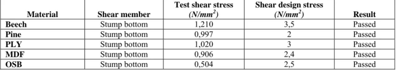
The maximum shear stresses determined in direction (Y) were compared to the allowable shear design stresses [2]. It has been determined that the maximum shear stresses occurred in member “stump bottom”
(E2,E9). The comparison results for shear stresses which act upon the stump bottom members of the sofa frames constructed of all the materials were given in Table 11.
Table 11. Comparison of the maximum shear stresses and shear design stresses
Material Shear member
Test shear stress (N/mm2)
Shear design stress
(N/mm2) Result
Beech Stump bottom 1,210 3,5 Passed
Pine Stump bottom 0,997 2 Passed
PLY Stump bottom 1,020 3 Passed
MDF Stump bottom 0,906 2,4 Passed
OSB Stump bottom 0,504 2,5 Passed
It has been determined that, for the section sizes of the members which are used in construction of the sofa frames, they have sufficient strength for carrying the shear forces. In the last phase, the bending moments in
direction (Z) which act upon all members of the sofa frames and consequential bending stresses were obtained from the results of the three dimensional analyses, and moment diagrams were given in Figure 8.
I. Type II. Type III. Type
Figure 8. Moment diagrams of the sofa frames
The maximum bending stresses in (Z) direction were obtained from the results of the three dimensional structural analyses, and then the obtained bending stress
values were compared to the allowable bending design stress values determined after tests for each material used in construction of the sofa frames (Table 12).
Table 12. Comparison of the maximum bending stresses and bending design stresses (N/mm2) Material
Bending member
Test bending stress Bending design stress
Result
Beech Stump bottom 60,476 43 Failed
Pine Stump bottom 49,851 25 Failed
PLY Stump bottom 50,982 22 Failed
MDF Stump bottom 45,298 11 Failed
OSB Stump bottom 25,208 11 Failed
The maximum bending stresses occurred in the tops of the members of “stump bottom” (E2,E9) where they were joined to the member of “side rail” (E18,E19). Therefore, the most critical places of the sofa frames are the joints where the stump connected to the side rail. Determined bending stresses values which act upon the mentioned joints have exceeded the allowable bending design stresses determined for each material. The bending strength of these joints and sectional properties
of these members have influenced the overall strength performance of the sofa frame systems. In designing the sofa frames, if these results are taken into consideration, the strength performance of the sofa frames can be increased.
All the forces with the corresponding stress acting on the ends of the members were analyzed and compared to the allowable design stresses determined for each
material used in the construction of the sofa frames. In conclusion, it has been understood that all materials used in the construction of the sofa frames and sectional sizes of each member could safely carry the axial (tension–compression) forces whereas the members of the stump bottom where they were joined to the member of the side rail has been imposed to over bending loads. This situation agreed with the actual performance testing results in terms of where the failures occurred. In the performance tests, the members of the sofa frames were not broken; firstly the openings happened in the mentioned joints, and then the openings occurred in the other joints. Consequently, it has been verified with the data of the computer aided structural analyses that the most critical places of the sofa frame systems are the joints.
4. CONCLUSION AND RECOMMENDATIONS
The glued-doweled joined sofa frames constructed of solid wood and wood composite materials yielded different mechanical behavior properties.
According to material types, significant differences were not found in mechanical behavior properties. The deformation characteristics of the sofa frames were eventuated almost the same, however it was observed that the quantities of the deformations were different. It was observed that the members of the sofa frame constructed of the materials which have high bending strength were deflected less, while the members of the sofa frame constructed of the materials which has low bending strength was deflected more. It has been obtained that the sofa frames constructed especially of beech and PLY were deflected less in terms of both general deflections of the system and bending of the members, relatively.
The sofa frames constructed of solid wood materials yield higher strength than the sofa frames constructed of wood composite materials. Although the sofa frames constructed of solid wood yield higher strength than those of wood composites, they could be commonly utilized in the furniture frames in engineering design approach because of their advantages such as dimensional stability and economical reasons. Although the wood composites are commonly used in box type furniture, their utilization in the frame type furniture is not widespread. It is recommended that wood composites could be used in the production of the frame type furniture, especially in the upholstered furniture frames.
The sofa frames constructed of beech and the sofa frames constructed of PLY has given close strength values. Therefore, PLY can be preferred to the solid beech and solid pine due to its many technical and economical advantages such as stability and feasibility
due to machining procedures in construction of the sofa frames. Similarly, the strength difference between the sofa frames constructed of MDF and the sofa frames constructed of solid pine was not significant. In this case, utilizing of the MDF in construction of the sofa frames instead of pine provides many technical and economical advantages for designers, producers, sellers and users.
The optimum place for the side slat has been found at the mid point between the side rail and arm like II. type side frame in the production of the sofa frames evaluated in this study. The most critical joints have been determined as stump–side rail connections. If it is necessary, the load bearing capacity of each three types of sofa frames can be augmented by increasing the strength of the joints.
As a result, the wood composite materials can be utilized in the furniture frames (especially frames of the upholstered armchair, sofa type furniture). But, in this case, it is important according to material type used that the addition of the side slat and giving a decision about its place in terms of the strength.
According to the performance test results, the most critical place in the furniture frames are joints. In other words, the strength of the joints used in the construction of the frames represent the overall strength of the furniture frame systems. The bending strength and sectional properties (moment of inertia) of the materials used in the constructions of the sofa frames have affected the strength of the joints. At the end of the structural analysis results, it was concluded that the joints of the sofa frames are subjected to considerable amounts of bending stresses. Therefore, it can be deduced that it is possible to obtain stronger joints and furniture frame systems by using such materials that have better bending strength properties.
According to the results of the three-dimensional structural analyses made by The Finite Element Methods; computer aided analysis programs provide reasonable estimates overall strength of the sofa frames tested in this study.
Today, computer technology is developing rapidly. Obtaining some advance information concerning the strength of the designed furniture before the production and optimization by making the needed changes according to this information will facilitate the furniture designer’s works, thus the economical deprivations can be prevented.
In conclusion, it has been thought that the high quality furniture that can rival in the world markets could be produced with the widespread use of developed methods, computer aided analyses, and performance tests.
REFERENCES
[1] Eckelman, C. A., Erdil, Y. Z., “Furniture Engineering and Quality of Life”, I. International Furniture Congress, İstanbul, 306-332 (1999).
[2] Kasal, A., “Masif ve Kompozit Ağaç Malzemelerden Üretilmiş Çerçeve Konstrüksiyonlu Koltukların Performansı”, PhD Thesis, Gazi University Institute Of
Science and Technology, Ankara, 27-28,
(2004).
[3] Efe, H., Erdil, Y. Z., Kasal, A., “Mobilya Mühendislik Tasarımında Mobilya Sistemlerinin Sonlu Elemanlar Metoduyla Optimizasyonu”, I. Advanced Technologies
Symposium, Ankara, 315-323 (2003).
[4] Cai, L., Wang, F., Tan, H., “Study on the Strength of Moltinject Corner Joints of Furniture”, Holz als Roh-und Werkstoff, 53 (6) : 385-388 (1995).
[5] Gustafsson, S. I., “Furniture Design by Use of the Finite Element Method”, Holz als
Roh-und Werkstoff , 53 (4) : 257-260 (1995).
[6] Gustafsson, S. I., “Finite Element Modelling Versus Reality for Birch Chairs”, Holz als
Roh-und Werkstoff, 54 (5) : 355-359 (1996).
[7] Gustafsson, S. I., “Optimising Ash Wood Chairs”, Wood Science and Technology, 31 (4) : 291-301 (1997).
[8] Smardzevski, J., “Numerical Analysis of Furniture Constructions”, Wood Science and
Technology, 32 (4) : 273-286 (1998).
[9] Smardzevski, J., “Strength of Profile-Adhesive Joints”, Wood Science and
Technology, 36 : 173-183 (2002).
[10] Daudeville, L., Davenne, L., Yasumura, M., “Prediction of the Load Carrying Capacity of Bolted Timber Joint”, Wood Science and
Technology, 33 : 15-29 (1999).
[11] Nicholls, T., Crisan, R., “Study of the Stress-Strain State in Corner Joints and Box Type Furniture Using Finite Element Analysis (FEA)”, Holz als Roh-und Werkstoff, 60 : 66-71 (2002).
[12] Erdil, Y., Z., “Integrated Product Engineering and Performance Testing of Furniture”, Ph.D. Thesis, Purdue University, West Lafayette, Indiana, 2-19 (2002).
[13] TS 46, “Kontrplak (Soyma Plakalı)–Genel Amaçlar İçin”, T.S.E. , Ankara, (1986).
[14] TS 64, “Lif Levhalar – Sert ve Orta Sert Levhalar”, T.S.E. , Ankara, (1982).
[15] EN 300, “Oriented Strand Boards (OSB)– Definitions, Classification and Specifications”, European Standart, (1997).
[16] American Society for Testing and Materials, Standard Methods of Evaluating the Properties of Woodbase Fiber and Particle Panel Materials, ASTM D 1037–98, ASTM, West Conshohocken, Philadelphia, (1998). [17] TS 3891, “Yapıştırıcılar–Polivinilasetat Esaslı
Emülsiyon (Ahşap Malzeme İçin), (Tadil AMD1: 1992 – 07)”, T.S.E. , Ankara, (1982). [18] TS 9024, “Mobilya – Koltuk”, T.S.E.,
Ankara, (1997).
[19] TS. 4539, Ahşap Birleştirmeler – Kavelalı Birleştirme Kuralları, T.S.E., Ankara, (1985). [20] TS 2471, “Odunda Fiziksel ve Mekanik
Deneyler İçin Rutubet Miktarının Tayini”,
T.S.E., Ankara, (1976).
[21] TS 9215, “Ahşap Mobilya–Mukavemet ve Denge Deneyleri”, T.S.E., Ankara, (1991). [22] ISO/DIS 7174/1, “Furniture–Chairs–
Determination of Stability”, Draft
International Standard, (1979).
[23] RISA – 3D Version 4.1, RISA Technologies, (2000).
[24] USDA Forest Product Laboratory, “Wood Handbook”, USDA Agricultural Handbook 72, USDA Forest Service, Forest Product
Laboratory, Madison, WI, USA, 42-45
(1987).
[25] Beer, F., P., Johnston, E., R., “Mechanics of Materials”, SI Metric Edition, McGraw – Hill
Ryerson Limited, 75-79 (1987).