PHYSICAL REVIEW
8
VOLUME 36, NUMBER 11 15OCTOBER 1987-IScanning-tunneling
microscopy
at
small
tip-to-surface
distances
S.
Ciraci* and InderP.
BatraIBMAlmaden Research Center, 650Harry Road, San Jose, California 95I20-6099 (Received 11 May 1987;revised manuscript received 12August 1987)
The scanning-tunneling microscopy (STM) of graphite at small tip-to-surface distances is in-vestigated using the self-consistent-field pseudopotential method. We have calculated potential, charge density in the region between the tip and surface, and the force corrugation. Our results reveal that the tip at the close proximity to the surface disturbs the states near the Fermi level, and induces localized states. The STM images, which are usually related to the local density of
states at the Fermi level ofthe clean surface, are affected by these localized states. The tunneling barrier is shown to collapse at small distances and a new mechanism for current is postulated. Some experimental evidence for this effect is presented.
In the scanning-tunneling microscopy'
(STM)
the dis-tance between the tip and the substrate surface(h)
is known to be acritical parameter, but it cannot beprecise-ly measured. The theory of the tunneling developed by
Bardeen assumes a wide and high potential barrier, in which the tails of the substrate and tip wave functions
slightly overlap. Based on this theory, Tersoff and
Hamann showed that the
STM
images the local density states at the Fermi levelp(r, EF
).
The Tersoft andHamann theory has been applied with reasonable suc-cess in identifying two distinct atoms on the graphite surface observed by
STM.
High asymmetry seenbe-tween these atoms was explained by Batra et aL and oth-ergraphite images by Mizes and Harrison. However, the explanation for "giant corrugation" continues to be con-troversial.
"
Atomic resolution has recently been report-ed' for graphite using atomic force microscopy(AFM).
'Recent
STM
studies have indicated the possibility that the elastic deformation due to the close proximity of the tunneling tip to the graphite surface may explain theob-served giant corrugation. A tip-to-surface distance, h,
as small as
2-3
A, is proposed.If
this is the case, theeff'ective potential barrier recedes or totally disappears,
and the current is expected to have a significant contribu-tion from nontunneling electronic states. In this work, we have investigated such a situation by using a simple mod-el. We have carried out standard self-consistent pseudo-potential calculations' in the momentum space' on a system consisting
of
the graphite surface and the tip with varying positions. Calculations of the electronic states, charge density, and atomic forces reveal important quali-tative results:(i)
The tip at the close proximity ofthe sur-face disturbs the graphite states near the Fermi levelin-duces a nonequilibrium (unstable) chemical bond, or lo-calized states in the vacuum region. These tip-induced states are expected to influence the
STM
images at con-stant VandI,
which are usually related top(r,
EF).
(ii) For small h, the repulsive tip force at the8
site'
has large value and large decay constant.It
is larger than the tip force at the0
site. This situation is, however, reversedwhen h isincreased to4.7a.u.
Present results are the first ab initio demonstration of the force corrugation in
AFM.
The elastic deformationmodel used to explain the giant corrugation at small bias voltage isbased on a similar force concept derived from an
empirical potential. Recently this elastic deformation model has been elucidated by Mamin et al.
"
The calcu-lation of the local deformation by using the present self-consistent field method is computationally not feasible,and therefore the giant-corrugation issue is beyond the scope of this study. Nevertheless, our study justifies the role of the tip-induced force in amplifying the charge-density corrugation.
To study the electronic structure and the total energy
we have used aperiodic tip within the repeating slab mod-el. The periodic tip is simulated by a single carbon atom
with an intertip distance
of
4.65 a.u.,corresponding tothesecond-nearest-neighbor distance in graphite. This cer-tainly produces an intertip interaction, which as deduced from the isolated monolayer calculations is, however,
small. At large tip-to-surface distance
(h=8
a.u.)
werealize that the intertip interaction is larger than the tip-surface interaction. Since, the intertip interactions are nearly constant for 2.7&h &8
a.
u. our qualitative con-clusions should not be affected by its presence. At small h(h=2.
7 a.u., which is comparable to the firstnearest-neighbor distance in graphite) the desired tip-surface
in-teraction plays a dominant role. This interaction is
deter-mined mainly by the outermost atom
of
the tip. Ap-parently, the representationof
the tip by a single atom is found to be appropriate.The graphite surface is represented by a three-atom-layer slab with an interslab distance of 1.5c
=18.
99 a.u.(c
being twice the interlayer distance). ' Clearly, for large
h, the interlayer interaction between
(0001)
planes isweaker than the intertip interaction, which is the artifact
of
the tip with small periodicity. In spite ofthat we use a multilayer slab ofgraphite for the following reasons: The first isto avoid the pathological singularitiesof
the graph-ite monolayer leading to an infinite corrugation;' the second is the comparison of the interlayer potential bar-rier with that occurring between the surface and the tip,which provides information about the collapse ofthe
tun-neling barrier atsmall h.
Plane waves having kinetic energy less than 10Ry are treated exactly, and those between 10and 13 Ry are in-cluded via the Lowdin's perturbation scheme. Sowe had
SCANNING-TUNNELING MICROSCOPY AT SMALL
TIP-TO-.
.
.
6195 $z ' ~2L 3L'
Qx,y = 1.5mdyn .~~=2.7a.u. N — 2l~
0.18mdyn Lh 4.7a.u.[a modest number
(-490)
of
plane waves to represent the Bloch states.It
is clear that the absolute total energies inour calculations with the
10-13-Ry
kinetic-energy cutoff are not converged. ' The absolute convergence in the present system requires a much larger basis set which isbeyond the current computational capacity. Therefore the calculated total energies should be used only for
rela-tive comparisons, and the values of the forces are good
only for getting qualitative trends.
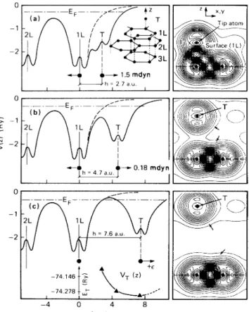
Figure 1 illustrates the contour plots
of
the total chargedensity and the interatomic forces calculated self-consistently for the tip being above the
B
site at three different valuesof
h. The potential barrier between the tip and the graphite surface calculated using the planarly averaged [one dimensional(ID)]
1=0
part ofthe nonlo-cal pseudopotential' isalso shown for each h. Forh=2.
7a.
u. we see that the potential barrier collapses, and a"bond"
is set up from the C 2p, orbitalsof
the tip andnearest surface atoms. The energy
of
the state associatedwith this bond, and those associated with C
2p„and
2p orbitals ofthe tip are located near the Fermi level. Their locations relative to the Fermi level are influenced by thevalue of h. Retracting the tip, and thus increasing h,
causes the bond (orthe localized states) to be delocalized gradually. Finally, the
C 2p„,
2p~, and 2p, orbitalsof
the tip become degenerate when h is much larger than the C—
C bond distance. Since the interaction between the surface and tip atoms is local, the above descriptionof
lo-calization would not be affected evenif
the tip isrepresented by a cluster
of
atoms. We arrive at this con-clusion by examining the charge density and the originof
the states near the Fermi level. As also seen from Figs.1(b)
and1(c),
upon retracting the tip the heightof
the po-tential barrier increases, and rises above the Fermi level. Calculated total energies and tip forces are listed in TableI.
For a given kinetic-energy cutoff, the interatomic forces require a very highSCF
convergence criterion. The error bars in TableI
arise from the modestSCF
con-vergence criterion (rms deviation in potential)—
5x
10 Ry used in the present study.A strong repulsive force
of
—
1.
5 mdyn(1
mdyn=10
N)
is exerted on the tip for h-2.
7 a.u. This force is bal-anced by a resultant reaction force distributed over the layers ofthe graphite.It
is large on the surface layer, but decays rapidly as one goes deeper into the bulk. However,in the present study the lattice parameters (lateral intera-tomic distance and interlayer spacing as well) are kept
fixed at their ideal values. Upon a tip-induced surface re-laxation, total energy
of
the tip forces are expected to be lowered. The elastic deformation induced by the tip is lo-cal, and hence the forces are expected to penetrate deep into the bulk causing large vertical deformations. The calculated values in TableI
indicate that the small h is a nonequilibrium state, and ET is lowered and the repulsivetip force is decreased with increased h. For example, the force between the tip and the surface is still repulsive for
h
=4.
7 a.u., but its magnitude is significantly reduced. Further retractingof
the tip (h=7.
6a.u.)
causes the mag-nitude ofthe force to diminish. Defining the potential en-ergy as the difference of the total energies corresponding tothe finite and infinite h,—74. 146--& CC vT (zj -74. 278--I 0 z(a.u.j
the zero force configuration at h
=7.
6 a.u. is seen to corre-spond to the minimumof
VT(h).
Further increaseof
h beyond this point leads the tip to enter into the attractive FIG. 1. Planarly average 1D pseudopotential V(z),intera-tomic forces, and contour plots of the total charge density for various tip-to-surface distances h. (a) h
=2.
7 a.u., (b) h=4.
7a.u., (c)h
=7.
6a.u. The inset in panel (a)describes the three-layer graphite slab and the carbon atom(T)
representing the tip. Total energies forvarious values ofh, ET,and the potential energy VT(h) curve obtained therefrom are shown in panel(c).
The averaged 1D potential V(z) with and without the tip atom are shown by the solid and dashed lines, respectively. The zeroofV(z) isset at the vacuum level. The filled circles denote the position ofthe carbon atoms. Thevalue ofthe total charge den-sity increases along the direction ofthe small arrows.
Er
(Ry) FT (mdyn) h-2.
7 a.u.—
74.080 1.49 h 4.7 a.u.—
74.278 0.18 h 7.6 a.u.—
74.292 0.0 TABLEI.
Calculated total energies (ET)and repulsive tip forces on the tip(Fr)
forvarying h above the8
site. The error bar due to the SCF-convergence criterion in calculated force values is4-0.
08mdyn (1mdyn 10 N).6196
S.
CIRACI AND INDER P.BATRA region. Soler, Baro, Garcia, and Rohrer used anempiri-cal potential for VT(h), which was fitted to the elastic constants ofthe graphite. They predicted that the tip goes from the repulsive toattractive region at h
=6.
3a.u.We performed similar calculations for the tip being above the
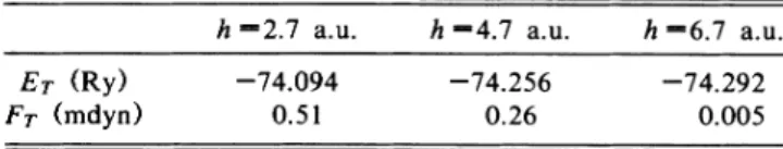
H
site with varying h. The interatomic forces obtained from these calculations are listed in TableII.
For h 2.7 a.u. the tip force at the8
site is much larger than that at theH
site. This situation is, however,re-versed when h is increased to
4.
7a.
u.,where the tip force at theH
site becomes larger than that at the8
site. On the other hand, the zero force (tip entering into attractive region)of
theH
site occurs at h~
6.
7a.
u. This implies a zero force corrugation between the8
andH
sites smaller than0.
9a.
u.It
should, however, be noted that owing to the relatively small slope ofFT(h)
near the boundarybe-tween repulsive and attractive force regions the calculated
values
of
h corresponding toFT(h)
=0
involve a large er-ror bar. Within the calculational parameters and the model used in this study this behaviorof
the tip force sug-gests the following explanation: At small h, the tip at8
site sees higher, but rapidly decaying, surface chargeden-sity relative to the
H
site. In the region say4~
h~
5 a.u.,the core-core repulsion force dominates the tip force, which islarge at theH
site. Accordingly, as compared to theH
site, the tip force at the8
site has large value andlarge decay constant for small h, but small decay constant for large h. Since the surface charge density calculated
within the repeating slab model is lacking reasonable ac-curacy for h
~
5.5 a.u.,the calculated small forces in this region have large error bars.In conclusion, by using a simple model we have studied the charge density, energetics, and interatomic forces
of
a system consistingof
a three-layer graphite slab and a periodic tip. The most striking resultof
this study isthat as h decreases the electronic statesof
the graphite and theTABLE
II.
Calculated total energies and repulsive tip forces with varying h above the Hsite. SeeTable Ifor further details.E,
(Ry) Fq (mdyn) h 2.7 a.u.—
74.094 0.51 h 4.7 a.u.—
74.256 0.26 h 6.7 a.u.—
74.292 0.005The authors wish to acknowledge fruitful discussions
with A. Baratoff,
G.
Binnig, Ch. Gerber, O.J.
Marti, H. Rohrer,S.
Chiang, M. McClelland,C.
F.
Quate,R.
J.
Wilson, H. Salemink, and
E.
Stoll.tip start tointeract, and form localized states. The locali-zation and the energy location
of
these tip-induced states depend on the type and the positionof
the tip atom, andundergo a gradual change as h varies. However, their effect onthe tunneling current may become almost sudden when their energies cross the Fermi level at awell-defined h and bias voltage (producing a resonant tunneling re-gime). At this particular tip-to-surface distance they are expected to make a significant contribution to the
tunnel-ing current. Marti ' has measured the tunneling current from graphite at low temperature as a function ofthe tip height from the sample. He noted that occasionally current changed by up toan order ofmagnitude within an
O.I-A change in the tip height. We take this as the
evi-dence for the collapse
of
the barrier and a transition to a chemisorption-type state shown in Fig.1(a).
Because of this tip-induced state theSTM
images, which under con-ventional circumstances are related tothe local densityof
states at the Fermi levelof
the clean surface, are strongly affected. Depending on the tip position, not only the total surface charge density, but also the core-core repulsion play acrucial role in determining the tip forces.Permanent address: Department ofPhysics, Bilkent Universi-ty, Ankara, Turkey.
G. Binnig, H. Rohrer, Ch. Gerber, and E.Weibel, Phys. Rev.
Lett. 49,57 (1982);50, 120
(1983).
2J.Bardeen, Phys. Rev. Lett. 6,57
(1961);
C.B.Duke, in Tun neling in Solids, Solid State Physics, Suppl. 10, edited byH. Ehrenreich, F. Seitz, and D. Turnbull (Academic, New York, 1969).
J.
TersoA and D. R. Hamann, Phys. Rev. Lett. 50, 1998 (1983);Phys. Rev. B31,805(1985).
~C.A.Selloni, P. Carnevalli, G. D.Chen, and E.Tosatti, Phys. Rev.B31,2602 (1985).
5I. P. Batra, N. Garcia, H. Rohrer, H. Salemink, E.Stoll, and
S.
Ciraci, Surf. Sci. 181,126 (1987);H.Salemink,I.
P. Ba-tra, H. Rohrer, E.Stoll, and E.Weibel, Surf. Sci. 181,139 (1987); I. P. Batra,S.
Ciraci, N. Garcia, H. Rohrer,H. Salemink, and E.Stoll, in Proceedings
of
the Eighteenth International Conference on the Physicsof
Semiconductors, Stockholm, 1986,edited by O. Engstrom (World Scientific, Singapore, 1986),p.57.D.Tomanek,
S.
G.Louie, H.J.
Mamin, D. W.Abraham, R.E. Thomson, E. Ganz, andJ.
Clarke, Phys. Rev. B 35, 7790(1987);H. A. Mizes and W. A. Harrison, in Proceedings
of
the Second Conference on Scanning Tunneling Micros copy/Spectroscopy
[J.
Vac. Sci. Technol. A (to bepub-lished)].
7G. Binnig, H. Fuchs, Ch. Gerber, H. Rohrer, E. Stoll, and
E.Tosatti, Europhys. Lett. 1,31 (1985).
sPark Sang-II and C. F. Quate, Appl. Phys. Lett. 48, 112 (1986);C.F.Quate, Phys. Today 39(No. 2),26(1986).
J.
M.Soler, A.M. Baro, N. Garcia, and H.Rohrer, Phys. Rev.Lett. 57,444 (1986).
'OJ.TersoK, Phys. Rev. Lett. 57, 440 (1986);
J.
B.Pethica, ibid57, 3235
(1986).
H.
J.
Mamin, E.Ganz, D. W.Abraham, R. E.Thomson, andJ.
Clarke, Phys. Rev. B 34,9015(1986).'2G. Binnig, Ch. Gerber, E.Stoll, T.Albrecht, and C.F.Quate, Europhys. Lett. (tobepublished).
'3G. Binnig, C.F.Quate, and Ch. Gerber, Phys. Rev. Lett. 56, 930
(1986).
' M. Schluter,
J.
R. Chelikowsky,S.
G. Louie, and M. L. Cohen, Phys. Rev.B 12, 4200(1975).
'
J.
Ihm, A. Zunger, and M. L.Cohen,J.
Phys. C 12, 4409SCANNING-TUNNELING MICROSCOPY AT SMALL
TIP-TO-. . .
6197 Graphite surface has two different atomic sites. The Bsite liesabove the center of the second-layer hexagram. The A site has a second-layer atom directly below. The
0
site denotes the center ofthe surface hexagram.'7R.C.Tatar and S.Rabii, Phys. Rev. B25,4126 (1982);
I.
P. Batra and L.Samuelson, Synth. Met.I,
223 (1979/80). 'SM.T.Yin and M.L.Cohen, Phys. Rev. B 33, 4294(1986).
I.
P.Batra, S.Ciraci, G.P.Srivastava,J.
S.Nelson, and C.Y.Fong, Phys. Rev. B 34, 8246 (1986);
I.
P. Batra,S.
Ciraci,and
J.
S.Nelson,J.
Vac.Sci.Technol. B5, 1300(1987). See, for example, P. Bendt and A. Zunger, Phys. Rev. Lett.50, 1684
(1983).
O.