1
Emerging Applications of Nanoparticles and Architectural Nanostructures. http://dx.doi.org/10.1016/B978-0-323-51254-1.00001-4Copyright © 2018 Elsevier Inc. All rights reserved.
Chapter
1
Liquid-phase synthesis of nanoparticles
and nanostructured materials
Ali Karatutlu*,**,†, Ahmed Barhoum‡,§ and Andrei Sapelkin† *UNAM-National Nanotechnology Research Center Bilkent University Ankara Turkey, Çankaya/Ankara, Turkey; **The Institute of Materials Science and Nanotechnology Bilkent University Ankara Turkey, Çankaya/Ankara, Turkey;
†Queen Mary University of London, London, United Kingdom; ‡Vrije Universiteit Brussel (VUB), Brussels, Belgium; §Helwan University, Helwan, Cairo, Egypt
1 INTRODUCTION
Many breakthroughs over 30 years have emerged following the advent of nanomaterials (NMs) research in natural sciences and engineering. Reduc-ing the size of materials down to nanoscale leads to produce NMs with pro-found changes in its physical properties relative to the macro scale form [1]. This results in applications of nanostructured materials including optoelec-tronics, magnetic storage memory devices, and biomedical applications. To manufacture such NMs, two main approaches are carried out as follows: (1)
top-down approach usually employs physical methods, for example,
me-chanical grinding, and (2) bottom-up approach often utilizes solution-phase chemistry, that is, wet chemical synthesis.
Liquid-phase synthesis methods have several advantages over other gas-phase and solid-gas-phase synthesis methods [2,3]. For example, (1) liquid-phase synthesis is the most common synthesis methods for preparing nanoparticles (NPs) and nanostructured materials together with the gas-state synthesis (Fig. 1.1) [4]; (2) size and shape control of NMs obtained could be achieved at low temperature within a short time from minutes to hours; (3) production of the NPs and nanostructures carried out with reasonably low-cost particularly compared to solid-phase synthesis methods; (4) exper-imental processes in the liquid-phase synthesis are rather simple with high mass yield; (5) conventional benchtop chemistry is applied with common reagents and equipment [5]; (6) surface functionalization can be achieved in situ with respect to the application field. This gives a complete control
on changing their physical properties; (7) size and shape of NPs and nano-structures could be controlled quite well by the most liquid-phase synthesis methods (depending on the method used). Chemical purification and size separation techniques, such as chromatography and high-performance liq-uid chromatography (HPLC) are not required; (8) postsynthesis techniques are available for formation of clusters [6] and 2d superlattices [7] from the as-prepared NPs and nanostructures.
The liquid-phase synthesis can be classified into: (1) top-down approaches, where bulk materials are etched in an aqueous solution for producing NPs or nanostructures, for example, the synthesis of porous silicon by electro-chemical etching; and (2) bottom-up approaches, where atoms/molecules via self-assembly, in general, are gathered together to form NMs and mixed in a controlled fashion to form a colloidal solution (Fig. 1.2). NPs produced by liquid-phase synthesis methods can remain in liquid suspension for further use or may be collected by filtering or by spray drying to produce a dry powder. Liquid-phase synthesis methods from a solution of chemical compounds include, but are not limited to, chemical stain etching, colloidal methods, coprecipitation, electrochemical deposition, direct precipitation, sol–gel processing, microemulsions method, reverse micelle synthesis, hydrother-mal synthesis, template methods, polyol method, and laser ablation. In this
■
■FIGURE 1.2 Schematic of the formation of NMs processes. Top-down versus bottom-up liquid-phase synthesis methods.
■
■FIGURE 1.1 Various methods for formation of NMs. The liquid-phase synthesis is reported as one of the most widespread synthesis technique together with the gas-state synthesis. (From Charitidis, C.A., Georgiou, P.,
Koklioti, M.A., Trompeta, A.-F., Markakis, V., 2014. Manufacturing nanomaterials: from research to industry. Manuf. Rev. 1, 11. under the CC BY 4.0 license).
3
2 Chemical stain etching
chapter, we attempt to explain the methods of the most common liquid-phase synthesis particularly with a purpose for helping new researchers to choose the best suitable liquid-phase synthesis methods for their interest. Because it is impossible to include all the published works, the other brilliant stud-ies and some of the liquid-phase synthesis methods left out involuntarily. An important subset of liquid-phase synthesis methods are sonochemistry methods and microwave-assisted methods, in which acoustic cavitation is used to control the process.
2 CHEMICAL STAIN ETCHING
Chemical stain etching is applied since the first studies on a bulk film of Ge and Si, respectively, where an aqueous HF/HNO3 solution was used as an etchant [8,9]. The solution continuously applies the etching process on the top surface of the oxidized bulk material from which NPs and nanostruc-tures are formed without any applied bias. In other words, the bulk mate-rial, such as intrinsic silicon, has a surface is inert against HF in a dark or an unbiased environment. Focus on optoelectronic applications using this method began after room temperature luminescence was observed in elec-trochemically etched Si in 1991 [10]. Still, the light emission using this solution was not satisfactory [11]. Various ratios, such as an aqueous HF/ HNO3 solution with a respective volume ratio of 500:1, were studied for improving the light emission [12]. Other oxidizing agents, such as H2O2, were also described [13].
Several other reaction conditions were reported. For example, the etch-ing rate was also found to be dependent on the dopetch-ing concentration [14]. Moreover, the metal-assisted oxidizing agents were also be found to be an efficient way for the formation of nanostructures [15,16]. Quenching and enhancement of the light emission have been observed to depend on the type of surface active agents (surfactants) [17,18]. Table 1.1 shows some examples of cationic and anionic surfactants.
The etching speed when forming nanostructures is also well known to be con-trolled by increasing the etchant acidity [13], such as HCl, H2SO4, and H3PO4 acids. On the other hand, ensuring good reproducibility of nanostructures us-ing stain etchus-ing solution can be difficult, several ideas, such as utilizus-ing a stronger etchant type [19], were found be an effective approach including flu-oroboric (HBF4), hexafluoro silicic (H2SiF6), hexafluoro antimonic (HSbF6), hexafluoro titanic (H2TiF6) acids. Despite the efficacy of the chemical stain etching method in the formation of NMs, extreme caution needs to be taken while dealing with HF acid solution and afterward, thus, this drawback can make researchers relatively hesitant to utilizing this method. Yet, the chemical
stain etching method in fluoride solutions can be performed at room tempera-ture under indoor light illumination or the UV irradiation [20]. Therefore, this method still seems to be appreciated due to yielding mass scale production of hydride and/or fluoride terminated NMs with narrow size distribution particu-larly when there are no replacements [21].
3 ELECTRODEPOSITION METHODS
Electrodeposition method, also known as electroplating, is an electric cur-rent driving deposition method gives a precise control of coating the species epitaxially in the form of NPs, nanowires, and so on, onto a conductive target material [22]. Electrodeposition is referred either to electroplating or to electrophoretic deposition (EPD). The electroplating process is usu-ally based on an aqueous solution of ionic species while EPD occurs in a suspension of particles. In electroplating, there is a charge transfer during the deposition to produce the metal or oxide layer in the electrode. In other words, positively charged ions in the electrolytic solution is reduced upon an external electric field applied so that they could be deposited onto a target material (cathode). In the EPD, deposition occurs without any chemical re-action involved (reduction) (Fig. 1.3). In fact, the principal driving force for EPD is the charge and the electrophoretic mobility of the positively charged particles in the solvent under the influence of an applied electric field, where the solvent should be organic in order to avoid water electrolysis. Another type of the electrochemical deposition is the electroless (autocatalytic) de-position in the presence of a reducing agent (dissolved in the electrolyte), which acts as the electron source for the redox reaction, and no external power supply is used [23].
Table 1.1 Names of Surfactant Used in the Chemical Stain Etching
Method for Formation of NMs
Surfactants Refs. OEGAE [17,18] Span80 MG DG OLA UDA CTAB SDS
CTAB, Cetyltrimethylammonium bromide; DG, diglyceride; MG, monoglyceride; OA, oleyl alcohol; OEGAE, oleyl ether glycolic acid ethoxylate; SDS, sodium dodecyl sulfate; Span80, sorbitan monooleate; UDA, undecylenic acid.
5
3 Electrodeposition methods
In general, the process of electrodepositing may be either: (1) an anodic process, where a metal anode is electrochemically oxidized in the solution, react together, and then deposit on the anode; or (2) a cathodic process, where components (ions, clusters, or NPs) are deposited onto the cathode from solution precursors. Film thickness could be controlled by the electro-deposition time, since increasing the reaction time would cause more source material to be consumed and yield larger film thickness. The deposition rate can be followed by the variation of the current with time. Electrodeposition has three advantages over other liquid-phase and gas-phase deposition tech-niques: (1) allow growing functional NPs through complex 3D nanotem-plates. Nanostructures and thin films can be deposited onto large specimen areas of complex shape, making the process highly suitable for industrial use. For example, electrodeposition can be performed within a nanoporous membrane, which serves to act as a template for NPs growth; (2) applicable at room temperature from water-based electrolytes; and (3) suitable to scaled down to the deposition of a few atoms or up to large dimensions, films thick-ness could range from a 1 nm to 10 microns. Deposition temperature and current density for the fabrication of metal NPs on semiconductor substrates
[24] were also shown to affect the deposition thickness.
To date, three different electrodeposition methods, including potentiostat-ic technique, galvanostatpotentiostat-ic technique, and pulse-plating techniques, were experimentally designated. In the potentiostatic technique, current density is changed under constant potential. In galvanostatic technique, electrode potential is varied with a constant current. In pulse-plating technique, the variation of pulse amplitude (e.g., 5V, 10V) and/or pulse width (from ns to
■
■FIGURE 1.3 Two types of electrodeposition processes. (A) Electroplating and (B) electrophoretic deposition (EPD) are schematically demonstrated. (From Santos, L., Neto, J.P., Crespo, A., Baião, P., Barquinha, P., Pereira, L., Martins, R.,
Fortunato, E., 2015. Electrodeposition of WO3 Nanoparticles for Sensing Applications. In: Electroplating of Nanostructures. InTech. under the CC BY 4.0 license).
µs) could be studied. When studying with electrodeposition methods, it is also common to refer to the method depending on the forms of the voltam-metry. Potential-step electrolysis method [25,26] and cyclic voltammetric technique [27] are such examples used to deposit Au NPs on substrates hav-ing a low electrical resistance, such as glassy carbon electrodes. In poten-tial-step electrolysis, applied voltage is increased from V1 to V2 at some time and current is measured over time. In cyclic voltammetric technique, the potential is swept back-and-forth between V1 to V2 and response on cyclic voltammograms (I-V) are studied in different experimental conditions (e.g., effect of impurities in electrolytes, their concentrations, and temperature). Multilayered NMs are prepared by pulsing or cycling the applied current or potential in a solution containing a mixture of precursors. The potential during the pulse determines the species deposited while the thickness of individual layers is determined by the charge passed. Alternatively, the sub-strate can be transferred periodically from one electrolytic cell to another. One of the early examples of the nanostructured materials fabricated via the electrodeposition method was shown for a Ni-Cu alloy in 1987 [28]. Since then, several metallic NMs including Au, Ag, Ni, Co, Fe, and Pt, were achieved by the electrodeposition methods [22]. Electrodeposition methods could also be used to decorate the conductive polymers onto nanostructured materials. For example, the conductive polymers were deposited onto the CNTs for sensing the glucose molecules [29–31]. Electrodeposition meth-ods were also reviewed for the applications of advanced ceramic materials and ceramic coatings [32].
4 DIRECT-PRECIPITATION METHODS
Direct-precipitation methods are used for precipitation of NPs within a con-tinuous fluid solvent. Metal salts, such as chloride, nitride, and so on, are dissolved in water. Metal cations exist in the form of metal hydrate species, for example, Al(H2O)3+ or Fe(H
2O6)
3+. These hydrates are added with basic
solutions, such as NaOH or NH4OH. CaCO3 particles of different sizes and morphologies can be produced by either mechanical (milling) or chemical routes [33]. The mechanical route often produces a mixture of vaterite, ara-gonite, and calcite and requires a long processing time to reduce the particle size below 1 µm. The chemical route has a lower energy consumption and gives better control over the product characteristics and purity. The precipita-tion condiprecipita-tions, such as the [Ca2+]/[CO
3
2−] ratio, pH, temperature, and
pres-ence of inorganic/organic additives, are the most important reaction factors
[34,35]. The control of these key parameters allows for preparing CaCO3 particles with sizes ranging from 50 nm to a few microns [36].
CO32-7
5 Sol–gel methods
Coprecipitation is a facile synthesis method generally reported for formation magnetic NPs and nanocomposites at low temperatures. The experimental parameters, including solution pH, reaction temperature, stirring rate, sol-ute, and surfactant concentration, give control on the formation of uniform, spherical, and high-purity NPs [37]. Since 1996, more than one-third of published studies (469 out of 1123) found in Scopus on the formation of NPs by coprecipitation methods include the synthesis of Fe3O4 NPs in vari-ous forms. The synthesis steps of the Fe3O4 NPs using the coprecipitation method are demonstrated in Table 1.2.
Coprecipitation method also gives an opportunity to alter the surface of NPs in a fast-postsynthesis procedure. Oleic acid modified Fe3O4 NPs were pre-pared by the coprecipitation method and their surface changed with DMSA in one step after the synthesis and obtained DMSA-coated Fe3O4 NPs [39]. Other examples of nanostructured materials prepared by coprecipitation method are PEG-coated Fe3O4 NPs [40], Ni-Zn-Fe NPs [41], CoFe2O4 NPs [42], Mn-doped ZnO NPs [43], and SiO2 NPs-polymer composites
[44]. The coprecipitation method could also be modified with an external alternating-current magnetic field [45], electric field, microwave or ultra-sonic irradiation [46].
5 SOL–GEL METHODS
The sol–gel process, involves the evolution of inorganic networks through the formation of a colloidal suspension (sol). The gel can be considered as a solid macromolecule immersed in a solvent. Gelation of the sol to form a network in a continuous liquid-phase (gel). The sol–gel process consists in the chemical transformation of the sol solution into a gel and with sub-sequent posttreatment and transition into solid oxide material. The sol–gel method is utilized since the 19th century to obtain materials usually for
Table 1.2 An Example of the Experimental Procedure
Is Demonstrated for the Formation of Fe3O4 NPs by the Coprecipitation Method [38]
Steps Solution I Solution II
I FeCl2.4H2O + FeCl3.7H2O NaOH solution II Surfactant (ammonium oleate)
III Precursor solution I Precursor solution II IV As-prepared Fe3O4 NPs
V Washing
VI Redispersion in surfactant solution VII Recovery of Fe3O4 NPs
inorganics and ceramics either matrix-free or embedded in a matrix. The history of sol–gel methods goes back to 1640 where Van Helmont precipi-tated SiO2 upon acidifying an alkaline silicate solution. In 1846, Ebelmen developed a transparent glassy material by exposure of silane prepared from SiCl4 and ethanol to the atmosphere [47]. However, the term “sol−gel” was proposed by Graham in 1864 during his work on silica sols [48]. More re-cently, uniform submicron and nanosilica particles are produced. Stöber et al. [48a] reported a pioneering method for the synthesis of spherical and monodisperse SiO2 particles ranging from 50 nm to 1 mm with a narrow size distribution by hydrolysis of an alkylorthosilicate using a mixture of water, alcohol, and ammonia as catalyst [49]. Nowadays, sol–gel technique is a common technology for fabrication of ultrafine powders, monolithic ceram-ics and glasses, ceramic fibers, inorganic membranes, aerogels, and other types of materials. This method was first applied in 1990 for the formation of nanoporous silica-titania films [50]. Since then, just via small changes in the experimental conditions, the method has evolved and NPs can be obtained in different nanostructured forms [51].
Sol–gel technique is one of the most popular solutions processing for NPs (mostly oxides) production. Formation of freestanding and colloidally stable metal oxide NPs concisely includes [52]: (1) hydrolysis of metal ions (M+y)
forming M(OH)x; (2) condensation of M(OH)x forming stable molecular clus-ters with oxo (M-O-M) or hydroxo (M-OH-M) bridges and generation of H2O as a by-product [51]; (3) growth of the nuclei by addition of reactive species (M(OH)x and clusters) available in the solution on the surface of the nuclei, forming colloidal sol NPs [53]; (4) coagulation of the MOx sol NPs by surface condensation reaction forming a rigid and porous inorganic network enclos-ing a continuous water phase, the “gel” [51]; (5) evaporation of the solvent and drying the gel via heat treatment or syneresis. Drying of the produced gel at 100°C results in a significant amount of shrinkage, densification, and for-mation of dry hard aggregates (xerogel); and (6) additional heat treatment in a reducing atmosphere, such as H2O gas medium for removal of oxides and for-mation of NMs embedded in a matrix. Controlled calcination of the xerogel at 500°C forming a porous structure, while the extensive heating usually from 400 to 700°C forms monodispersed NPs. In the sol–gel method, precursors and their concentrations are carefully chosen in order to determine the desired NMs formation and surrounding matrix. For example, the same precursor with different concentrations could be used for controlling the size of NPs. Using the sol–gel method, various NMs become available in mass-produc-tion, including group 14 semiconductor nanocrystals [54], TiO2 NPs from a different precursor [55] with various morphologies [56], and different dopants [57,58] were prepared by sol–gel method. Magnetic SrFe12O19 NPs with controllable morphologies [59], magnetic ferric oxide (Fe2O3) NPs
9
5 Sol–gel methods
[60], LiFePO4 NPs [61] as a cathode material, XCuZn ferrite NPs (where X = Ni [62] or Mg [63]), Fe2O3/Al nanocomposites [64].
Depending on the application, the final product can be obtained in NPs, nanofibers, or coatings, such as thin film [65].
The most common applications of sol–gel process is the fabrication of vari-ous coatings and films are: (1) dip-coating: the substrate is immersed into a sol solution and then withdrawn with a well-defined speed under controlled temperature and atmospheric conditions [66]. Electrochemical sensors, such as CNTs-coated electrodes [67], could be formed using a dip-coating despite the risk of agglomeration of NMs at the surface of coated material. An additional heat treatment after dip-coating might be required to obtain more dense coating. (2) Spin coating: sol solution is poured over the surface of flat substrate and spun off to leave a uniform coating layer on the sub-strate. Some industrial examples are photoresist coating and compact disc recordable (CD-R) and could be also used to obtain NPs assembled onto the surface of the substrate [68]. Furthermore, freestanding nanostructures are available and could be prepared via layer-by-layer (LBL) assembly us-ing spin coatus-ing [69]. (3) Spray coating: sol solutions are sprayed over the surface of flat substrate. Fig. 1.4 shows a schematic representation of the
■
■FIGURE 1.4 The steps for the
formation of a nanostructured zinc titanate film via sol–gel route, which utilize an amphiphilic diblock copolymer, poly(styrene-block-ethylene oxide) P(S-b-EO), as the structure-directing template are schematically represented. (A) The ZnO sol preparation when zinc acetate dihydrate used as the precursor, (B) the TiO2 sol preparation when ethylene glycol-modified titanate used as the precursor, (C) the two sols are mixed together to obtain the final zinc titanate sol, (D) spray deposition of zinc titanate sol is given, (E) zinc titanate hybrid film is given after the spray-deposition step, (F) the final step includes a calcination process to take away the polymer template resulting in pure nanostructured film. (From The Royal Society
of Chemistry; Sarkar, K., Braden, E. V., Fröschl, T., Hüsing, N., Müller-Buschbaum, P., 2014. Spray-deposited zinc titanate films obtained via sol–gel synthesis for application in dye-sensitized solar cells. J. Mater. Chem. A 2, 15008–15014).
multistep process involved in producing Zn2TiO4 nanostructures via a tem-plate-assisted sol–gel route [70]. (4) Flow coating: the liquid coating system is poured over the substrate to be coated. The coating thickness depends on the angle of inclination of the substrate, viscosity of the coating liquid and solvent evaporation rate [71]. NP assemblies in large scales [71,72]
can be formed with both parallel and crossed stripe patterns. The velocity profile of the substrate (present on a translated stage) controls the spacing between NPs. (5) Capillary coating: a tubular dispense unit is moved under the substrate surface without physical contact. A spontaneous meniscus is created between the top of the slot tube (or porous cylinder) and the sub-strate surface, and achieving laminar deposition with high uniformity [73]. Using this method, various NMs-based capillary coating studies [74] were demonstrated including CNTs, graphene, metallic NPs, and magnetic NPs. (6) Roll coating: a thin liquid film of sol solution is uniformly formed on a continuously moving substrate by using rotating rolls [68]. This technique could be combined with liquid flame spray method to have nanostructured coatings [75,76] with 10–50 nm coating thicknesses. (7) Electrospinning: nanofibers are produced using an electric force to draw charged threads of gel solutions. Then, these nanofibers would move and reach to a lower potential collector plate. Solution parameters, including molecular weight, solution viscosity, solution conductivity; environmental parameters, such as temperature, humidity; and processing parameters, such as voltage, flow rate, the morphology of collector and tip-collector distance would influence the morphology of nanofibers [77]. The research progress on nanofibers us-ing electrospinnus-ing were demonstrated for applications in nanomedicine
[78] and Li-ion battery separators [79] with properties, such as large surface area and high porosity yielding high loading capacity, high encapsulation efficiency, and low preparation cost.
Overall, the sol–gel method could be utilized for obtaining NPs and nano-structures with various sizes and shapes for the desired physical and chemi-cal properties, however, the reaction time and heat treatment processes are generally long, and thus, a high operational cost could be a challenge.
6 COLLOIDAL SYNTHESIS METHODS
Colloidal synthesis methods are simple and well-established wet chemistry precipitation processes in which solutions of the different ions are mixed under controlled temperature and pressure to form colloidal suspensions or insoluble precipitates. Colloidal synthesis is the quickest wet synthesis methods to create colloidal suspensions is by using the aqueous reduction of soluble metallic complexes [80]. The scientific investigations of colloidal
11
6 Colloidal synthesis methods
synthesis methods started only in 1857 when Faraday has published results of his experiments with Au NPs. Faraday prepared Au colloids by reduction of HAuCl4 with phosphorus. Today, colloidal processes are widely used to produce such NMs like metals, metal oxides, organics, and pharmaceuticals. Metallic colloidal NPs are prepared by mixing of few chemicals including a precursor, solvents, a reducing agent, and a surfactant. As a source of NPs at a certain size, the type of precursors are chosen in a particular concentration. The solvents are used to dissolve the precursor and become the solution. Then, a surfactant is included to prevent agglomeration of the NPs when the formation of NPs starts. Finally, the reducing agent is added into this solu-tion to initiate the reacsolu-tion for formasolu-tion of NPs.
The synthesized NPs have very high surface energies and will tend to ag-glomerate and form larger structures to reduce their surface energy. To pre-vent NPs aggregation and maintain a stable colloidal solution, a stabilizer “capping agent” in the form of a surfactant or an organic polymer is added to restrict particle growth and stop interparticle agglomeration. Therefore, the correct combination of metal concentration and stabilizer (capping agent) will efficiently produce monodispersed metallic NPs. Furthermore, to improve the output from this type of reaction process, various metallic complex precursors, reductants, and different growth media are available. Moreover, even using a two-step reaction instead of a single-step reaction can produce different types of NPs from the same initial raw materials. For example, a two-step reaction involving hydrolysis of an alkoxide followed by reduction to metallic Ge was demonstrated for the fabrication of germa-nium inverse opals from a colloidal template [81].
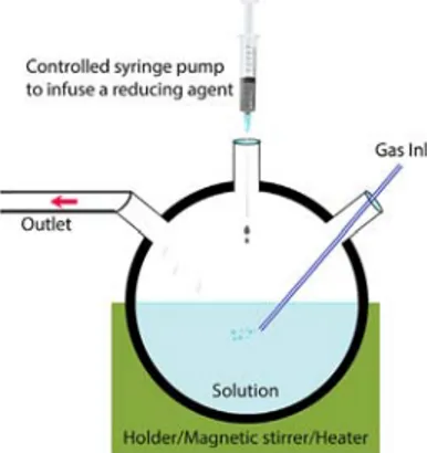
The high quality of NPs here can be discussed in combination with their high-colloidal stability, high-quantum yield, high-surface stability, high photostability, and/or high-magnetic saturation. The equipment used in the colloidal synthesis can indeed be cost-effective to prepare such high-quality NPs. Sometimes, the solution prepared from a precursor, a solvent, and a surfactant can be prepared within a syringe added by a syringe pump into a beaker where a reducing agent resides. These conditions are subsequently led from minutes to a few hours to nucleation and growth of inorganic NPs with an option of capping with organic ligands.
Occasionally, NPs can also be prepared with hydrogen termination on their surface, which can be stable for some time at the ambient atmospheric envi-ronment. The heat treatment or high pressure inserted into the reaction and its rate can be important and even required in some cases for making NPs in crystalline form, which are so-called colloidal nanocrystals. In most of the studies, the size of NPs is found to be dependent on the concentration
and the type of surfactants, the reaction temperature, and the time required for the formation of NPs. The size of NPs can also be dependent simply on the type of the inert gas used, such as Ar or H2 Ar used during the purging the reaction solution in order to prevent oxidation of NPs even if all other parameters are the same.
High-quality core/shell nanocrystals can be prepared using colloidal syn-thesis, including two different layers surrounding one another [82,83]. It is also common to obtain LBL preparation to form colloidal nanocrystals with more than two layers. There are various reasons to choose to increase the number of layers. The first reason is to improve the quantum yield and the second is to terminate the leakage of toxic ions, such as Cd+2 from the
core to the ambient environment. There are other effects, such as prepar-ing a “giant” multishell, that would suppress photobleachprepar-ing and make NPs photostable for a reasonable experimental time, such as about an hour [83]. On the top of such layers, a functionalized surface can also be added for specific purposes, such as for the water solubilization strategies required within biomedical applications [84].
The colloidal chemistry applied to form such NPs includes cases for semi-conductors, metal chalcogenides, metallic/metal alloys, and magnetite/he-matite NPs. A challenging issue with metallic NPs is to be able to cease the reaction as nucleation/formation of NPs are really rapid. This is im-portant for controlling the size of NPs and reducing the size distribution of NPs. This issue is solved by preparation of small-sized metallic NPs at first, which are then exploited as the seeds of larger NPs.
In the colloidal synthesis of NPs, the hot-injection synthesis and solvother-mal methods, including the microwave-assisted method, are subclasses of colloidal synthesis methods. These methods are highlighted one after an-other henceforth.
7 HOT-INJECTION SYNTHESIS METHODS
In the hot-injection synthesis method, the reaction vessel is heated from room temperature to 300°C where surfactants are placed in a solvent as schematically demonstrated in Fig. 1.5 so that organic capping agents could bind to the NPs surface to prevent agglomeration of NPs [85]. This process is widely applied because it directly provides colloidal NPs at the end of one-step synthesis.
Table 1.3 shows various examples of NPs prepared using the hot-injection synthesis. In order to avoid the aggregation of NPs and improve their per-formance, a seed-mediated hot-injection approach to synthesize highly dispersed tiny NPs on a nanosized solid support (Fig. 1.6). This simple,
■
■FIGURE 1.5 A schematic of the hot-injection synthesis method.
13
7 Hot-injection synthesis methods
low-cost, and effective chemical approach allows for synthesizing highly uniform metal NPs (∼10 nm) on the surface of nanoscale solid support without aggregation of the metal NPs. In some cases, in order to lead a homogeneous heat treatment over the reaction, the microwave is operated
Table 1.3 Summary of the Thermolyzes Method Applied for Various NMs
NMs Precursors Solvent or surfactant T/˚C Size range (nm) Refs.
In2O3, ZnO, CoO, MnO2
Metal carboxylate (Ac, Mt, or St) ODE, OA, or DA 250–280 [6]
In2O3 Indium carboxylate (Ac, Mt, or St) ODE, DA 250–290 15–60 Fe3O4 FeCl3, NaOH DEG, PAA 220 30–180 PbS Pb(Ac)2, thiourea DEG, PAA 215 155–240 ZnO Zn(Ac)2, NaOH DEG, PAA 210 60–180
CdE (E = S, Se, Te) Me2Cd, (TMS)2S, (TMS)2Se, (BDMS)2Te TOP, TOPO 180–300a 1.2–11.5 [86]
Si SiCl4 TOAB, LAH-THF, ALA RT 1–2 [5]
Ge GeO2 EG, PVP, NaOH 60 2–5 [87,88]
Ge GeCl4 EG, PVP, triglyme RT 3–20 [89,90]
C γ-BTL CSA, NCO, H2O 100 20–30 [91]
GeTe GeI2 TOP, Te-TOP, TOPO 250 2.5–4.5 [92]
Au HAuCl4 MSG, NaOH ≥254 17–53 [93]
γ-BTL, γ-Butyro-lactone; (TMS)2S, bis(trimethylsily1) sulfide; Ac, acetate; ALA, allylamine; CIT, citrate; CSA, concentrated sulfuric acid; DA, decyl alcohol; DEG, diethylene glycol; EG, ethylene glycol; GeCl4, germanium tetrachloride; GeI2, Germanium(II) iodide; GeO2, Germanium oxide; HAuCl4, chloroauric acid; LAH-THF, lithium aluminum hydride solution in lithium tetrahydroaluminate; MSG, monosodium glutamate; Mt, myristate; NaOH, sodium hydroxide; NCO, Aqueous Na2CO solution; OA, octadecyl alcohol; ODE, 1-octadecene; PAA, polyacyl acid; PEG, polyethylene glycol; PVP, polyvinyl pyrrolidone; RT, room temperature; SiCl4, silicon tetrachloride; St, stearate; Te-TOP, Telluride-TOP solution; TOAB, tetraoctyl-ammonium bromide in toluene; TOP, trioctylphosphine; TOPO, Tri-n-octylphosphine oxide; triglyme, sodium borohydride in triethylene glycol dimethyl ether.
aThe growth temperature is varied from the injection temperature of the solvents.
Source: From Lu, Z., Yin, Y., 2012. Colloidal nanoparticle clusters: functional materials by design. Chem. Soc. Rev. 41, 6874–87 with permission from The Royal Society of Chemistry.
■
■FIGURE 1.6 TEM images at different magnifications for tiny Ag NPs on CaCO3 as a nanoscale solid support. (From Barhoum, A., Rehan,
M., Rahier, H., Bechelany, M., Van Assche, G., 2016. Seed-mediated hot-injection synthesis of tiny Ag nanocrystals on nanoscale solid supports and reaction mechanism. ACS Appl. Mater. Interfaces 8, 10551–10561. Copyright 2016 American Chemical Society).
instead of conventional heating. This method is known as microwave-assist-ed (colloidal) synthesis methods and will be given separately.
8 HYDROTHERMAL AND SOLVOTHERMAL
METHODS
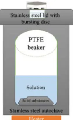
In the hydrothermal/solvothermal methods, the reaction is heated over the boiling points of precursors. As schematically shown in Fig. 1.7, the reaction for the formation of NPs is generally performed in a closed steel autoclave, therefore, the relationship between temperature, volume, and pressure in the vessel must be considered before initiating the synthesis. Some examples of NPs formed using hydrothermal/solvothermal methods are given in Table 1.4. The chemical composition of the precursors and the selection of the solvent at optimum temperatures and pressures lead to NPs with various sizes and shapes. Water, as a solvent, for example, is one of the greenest solvents available, which would show anomalous behaviors when approaching the critical point where T = 374°C and P = 22.4 MPa. This information can play role in the creation of the different reactor designs for the synthesis of NPs, including that used in the continuous flow hydrothermal synthesis of metal oxides in supercritical water [96].
9 MICROWAVE-ASSISTED SYNTHESIS METHODS
Microwave-assisted methods have been widely applied in chemical reac-tions and synthesis of NPs and nanostructures. It is an attractive choice to promote reactions and is energy-effective heating compared to conventional■
■FIGURE 1.7 A schematic of
conventional hydrothermal/solvothermal methods.
Table 1.4 Summary of the Hydrothermal/Solvothermal Methods Applied for Various NMs
NMs Precursors Solvent or surfactant T/˚C Size Range/nm Refs.
MFe2O4 (MQFe, Co, Mn, Zn)
FeCl3, MCl2, NaAc EG, PEG 200 200–800 [6]
Fe3O4 Fe(acac)3 EG, PVP 140–145 50–100 Fe3O4 FeCl3, NaAc EG, DEG, sodium acrylate 200 6–170 MFe2O4 (MQFe, Mn, Zn,
Co, Ni)
FeCl3, MCl2, NaAc EG, DEG, PVP 200 20–300 Fe3O4 FeCl3, NaAc EG, Na3Cit 200 170–300 a-Fe2O3 FeCl3, urea THF, ethanol, PVP 180
Sb Sb(NMe2)3 TOP, OLA 150–200 10–20 [94]
Pt K2PtCl6 Na3Cit, H2O ≥250 34 [95]
CIT, citrate; DEG, diethylene glycol; EG, ethylene glycol; K2PtCl6, potassium hexachloroplatinate (IV); OLA, oleylamine; PEG, polyethylene glycol; PVP, polyvinyl pyrrolidone; TOP, trioctylphosphine.
Source: From Lu, Z., Yin, Y., 2012. Colloidal nanoparticle clusters: functional materials by design. Chem. Soc. Rev. 41, 6874–87 with permission from The Royal Society of Chemistry.
15
9 Microwave-assisted synthesis methods
heat conduction methods (such as an oil bath) due to the direct heating of the reaction mixture [97].
Microwave heating offers many advantages over conventional heating. Microwaves are a form of electromagnetic radiation with frequencies be-tween 300 MHz and 300 GHz and wavelengths bebe-tween 1 m and 1 mm. Nevertheless, in order to prevent interference with telecommunication and radar equipment, it is common for industrial and domestic microwave ap-paratus to be designed to operate at 2.450 ± 0.050 GHz (corresponding to ≈12.24 cm in wavelength) [98]. Microwave ovens provide rapid heating compared to conventional conduction and convection heating systems. Mi-crowave has a rapid processing time, 2 to 50 times faster than conventional heating. The rapid heating in this case is caused by the microwaves inducing the fast rotation of dipoles and production of thermal energy, which heats the material [99]. This means that a polar solvent is needed for microwave-assisted synthesis and the higher polarity of solvents will result in the higher generation of the heat upon the microwave irradiation. Polar solvents heat easily throughout the whole volume. This is in direct contrast to the hot plate conventionally used in most liquid-phase synthesis methods, where the ther-mal energy is transferred by conduction and therther-mal convections. Nonpolar solvents mixed with small amounts of polar solvents could also be used in the microwave-assisted synthesis of NPs due to the fact that energy transfer between the polar molecules and the nonpolar solvent is rapid. Furthermore, microwave-assisted synthesis is known to produce an increase of the boil-ing points of organic solvents, which was considered to be due to “nucleate boiling” [100]. To date, various types of microwave reactors specifically designed to perform specific chemical reactions. Generally, a specially de-signed pressure-rated Teflon-lined vessel is used to contain the reactants to avoid any pressure buildup and possible explosions.
The use of microwaves was first reported by Gedye et al. [101] for rapid organic synthesis, observing the advantages of this technique. Since then, microwave-assisted synthesis of NMs has been found to be promising and combined with other wet-state synthesis methods [98], including microwave autoclave meth-ods, a modified version of the conventional hydrothermal methods; reflux sys-tems; and microwave-assisted nonaqueous sol–gel methods. Some examples of such microwave-assisted synthesis were reported for graphene-containing NMs [102] for lithium-ion batteries. Other examples of microwave-assisted synthesis of NMs include ZnO NPs [103] with different morphologies [104], Ag NPs [105,106], Cu NPs [107], Co3O4 NPs [108], composites of metal [109]/ metal oxide [97] NPs supported with CNTs and RE-doped YPO4 (RE = Eu, Ce, Tb and Ce + Tb) nanophosphors [110]. Fig. 1.8 represents a schematic of the production process of ZnO seed layer and the subsequent synthesis of ZnO
nanorod arrays. After uniformly coating the glass substrates with ZnO thin films, ZnO nanorod arrays were synthesized by hydrothermal method assisted by microwave radiation. The ZnO seeded substrates were placed at an angle against the vessel, with the seed layer facing down [111].
10 ULTRASONIC SYNTHESIS METHODS
Ultrasonic synthesis methods have emerged as a powerful synthesizing technique to prepare NP nanostructured materials. The ultrasound fre-quency range is above 20 kHz and can reach frequencies in the gigahertz level. By applying the ultrasonic radiation to the precursor solution, the chemical reaction is initiated. As a form of radiation, ultrasound has the capacity to break chemical bonds and create products. The sudden im-plosion of the bubbles (about 100 µm in size) creates a local hot spot, which can reach temperatures as high as 5000K and pressures of up to hundreds of atmospheres depending on the level of ultrasound power used. At the same time, the cooling rates are extremely high and can be as great as 1011 K/s [99]. The capacity of ultrasound to create these extreme
■
■FIGURE 1.8 A schematic of the ZnO seed layer deposition is demonstrated. The spin-coating method is treated first by ZnO nanorod arrays. Then, the ZnO seed layer deposited substrate was placed in a vial for the hydrothermal method assisted by microwave radiation. (From Pimentel, A., Ferreira,
S., Nunes, D., Calmeiro, T., Martins, R., Fortunato, E., 2016. Microwave synthesized ZnO nanorod arrays for uv sensors: a seed layer annealing temperature study. Materials (Basel). 9, 299. under the CC BY 4.0 license).
17
10 Ultrasonic synthesis methods
temperatures and pressures within a medium makes this technique attrac-tive. The ultrasound leads to creation, growth, and rapid collapse of small bubbles, which act as nucleation centers. The growth of nucleus ends after bubble collapse. Size and shape selection in ultrasound synthesis is ac-complished by controlling the precursor concentrations, pH, temperature, and surfactant concentration.
Facile synthesis of fuel cell materials containing metallic NPs [112] was demonstrated via ultrasonic synthesis method in the absence and presence of surfactants and alcohols. Nanostructured photocatalysts [113] were also prepared using ultrasonic synthesis method. Recent studies on Ag NPs
[106], carbon NPs [114], nanosized MOFs [115,116], silica NPs [117], Pd-Sn NPs [118] also present ultrasonic synthesis method to be promising for the formation of various NPs systems. Besides, ultrasound synthesis meth-ods are used not only for the synthesis of NMs but also for other purposes, such as loading NPs inside nanotubes or surface functionalization of NPs with polymers. Ag NPs-loaded TiO2 nanotubes [119] and Pt NPs-loaded CNTs [120] were demonstrated for loading NPs inside nanotubes via ultra-sonication. On the other hand, polymerization [121] has also been known for 30 years to be initiated via ultrasonication. This knowledge was applied, for instance, for the ultrasonic synthesis of iron NPs and their surface stabi-lization using polymers ([122]; 1998).
Teo et al. have prepared 100 nm latex beads loaded with a high content of Fe3O4 NPs via encapsulation of Fe3O4 NPs with latex beads under the ultrasound-initiated effect is well illustrated in Fig. 1.9. The NPs exhibited excellent colloidal stability and superparamagnetic properties (24 emu/g), and were of the desired size to be technologically relevant [123].
■
■FIGURE 1.9 Encapsulation process of Fe3O4 NPs through sonochemically driven miniemulsion polymerization of monomer droplet to latex particle is schematically demonstrated. (From Teo, B.M., Chen, F., Hatton, T.A., Grieser, F., Ashokkumar, M., 2009. Novel one-pot synthesis of
11 LASER ABLATION IN LIQUID-PHASE
The laser ablation has been operated since the invention of the ruby laser in the 1960s [124]. After the 1980s, a wide range of NMs in ambient condi-tions [125], in gas [126] or in liquid-phase [127] were become available by this method. The laser ablation in the liquid-phase includes a high power laser, an optical focusing system, a bulk target, and a liquid. The laser beam generally produced by a nano/femtosecond pulsed laser system is directed by the optical components onto the bulk target inside a liquid host as shown in Fig. 1.10.
The laser ablation for synthesis of NPs can happen either in gas or liquid phase. The main differences between ablation in liquids and ablation in gas phase/vacuum that ablation occurs at the boundary between the solid and liquid phase or the solid and the gas, respectively. The laser ablation in liq-uids is more efficient because the formation and distribution of the plasma plume occurs in the liquid environment, liquids have a much higher thermal conductivity than gas. In general, a large number of chemical transforma-tions are possible in liquid phase, the process mechanisms, aggregate states, and phase transitions depending on the pulse duration in temperature-densi-ty coordinates. Fig. 1.10 shows the ablation process and the formation of a plasma cloud (Fig. 1.10A) in the liquid phase.
The first study of the laser ablation in the liquid-phase was performed in 1987 when pure iron in liquid ammonia was ablated for nitridation of iron
■
■FIGURE 1.10 Laser ablation in liquid-phase is demonstrated using a nanosecond-pulsed laser. (A) Laser pulse is absorbed and a plasma plume is formed, (B) the laser plasma is evolved and interacted with radiation, (C) the plasma is further evolved and the chemical reactions inside the plume and at the border are given, (D) the nanoparticles are formed/diffused in liquid and the substrate surface is eroded. (From: Svetlichnyi, V.A., Shabalina, A.V,
Lapin, I.N., Goncharova, D.A., 2016. Metal oxide nanoparticle preparation by pulsed laser ablation of metallic targets in liquid. In: Applications of Laser Ablation - Thin Film Deposition, Nanomaterial Synthesis and Surface Modification. InTech. Under the CC BY 4.0 license).
19
12 Conclusions
[128]. This was later shown successfully to produce photoluminescent sili-con NPs [129] with a possibility of tuning their size [127]. These studies were later expanded within various liquid hosts for the formation of Si and Ge NMs [127,130,131]. The examples of the NMs formed from several bulk targets [132] are shown in Fig. 1.11. Here, various liquid hosts were re-ported, including water, ethanol, acetonitrile, dimethylformamide, tetrahy-drofuran, dimethylsulfoxide, and toluene.
Upon the exposure of the laser light onto the bulk target surface, the extreme temperatures and pressures are reached at the target-liquid interface, which may result in the vapor of the solid target with some amounts of the sur-rounding liquid. In other words, the interaction of the laser light with the bulk target yields an ablation plume [125]. The ablation plume contains very energetic atoms, ions and/or molecules of the bulk material expanding to the environment throughout the liquid host. The liquid host is chosen in a way that it should not be absorbing the laser light and shall interact with NMs for possible surface functionalization. Overall, the colloidal NMs as a product from various bulk targets and the liquid hosts [132] can be formed via the laser ablation in the liquid-phase.
12 CONCLUSIONS
We reviewed most of the liquid-phase synthesis methods from a solution of chemical compounds for formation of NPs and nanostructured materi-als, including developments of the methods for the purpose of low cost,
■
■FIGURE 1.11 Summary of NMs formed by laser Ablation in the liquid phase.
(Reproduced with permission from the PCCP Owner Societies; Amendola, V., Meneghetti, M., 2013. What controls the composition and the structure of nanomaterials generated by laser ablation in liquid solution? Phys. Chem. Chem. Phys. 15, 3027–46).
high quality, low toxicity, and desired surface functionality. The liquid-state synthesis methods reviewed here include chemical stain etching, electro-deposition methods, direct-precipitation methods, sol–gel methods, colloi-dal synthesis methods, hot-injection synthesis methods, hydrothermal and solvothermal methods, microwave-assisted synthesis methods, ultrasonic synthesis methods, and laser ablation in liquid-phase. From the biomedical perspective, such NPs are expected in the near future to be established from noninvasive targeted superresolution imaging applications and clearing NPs from animal/human bodies to therapeutics. On the other hand, new reci-pes or progress in the synthesis is demanded by electronic industry which requires the use of NMs for specific purposes, such as in composites with reproducible electrical conductivity and boosting the efficiency of rotating electrical machines. Nanostructured materials, including CNTs and nanopo-rous materials, are the last but not the least examples of near future applica-tions, which are planned to be made optimum for low-cost and large-scale environmental pollution control, including trapping greenhouse emissions and cleaning harmful pollutants in water.
REFERENCES
[1] A.P. Alivisatos, Semiconductor clusters, nanocrystals, and quantum dots, Science 80 (271) (1996) 933–937.
[2] J. Feng, G. Biskos, A. Schmidt-Ott, Toward industrial scale synthesis of ultrapure singlet nanoparticles with controllable sizes in a continuous gas-phase process, Sci. Rep. 5 (2015) 15788.
[3] A. Gutsch, H. Mühlenweg, M. Krämer, Tailor-made nanoparticles via gas-phase synthesis, Small 1 (2004) 30–46.
[4] C.A. Charitidis, P. Georgiou, M.A. Koklioti, A.-F. Trompeta, V. Markakis, Manufac-turing nanomaterials: from research to industry, Manuf. Rev. 1 (2014) 11.
[5] X. Cheng, S.B. Lowe, P.J. Reece, J.J. Gooding, Colloidal silicon quantum dots: from preparation to the modification of self-assembled monolayers (SAMs) for bio-applications, Chem. Soc. Rev. 43 (2014) 2680.
[6] Z. Lu, Y. Yin, Colloidal nanoparticle clusters: functional materials by design, Chem. Soc. Rev. 41 (2012) 6874–6887.
[7] S.-K. Eah, A very large two-dimensional superlattice domain of monodisperse gold nanoparticles by self-assembly, J. Mater. Chem. 21 (2011) 16866.
[8] R.J. Archer, Stain films on silicon, J. Phys. Chem. Solids 14 (1960) 104–110. [9] C.S. Fuller, J.A. Ditzenberger, Effect of structural defects in germanium on the
diffusion and acceptor behavior of copper, J. Appl. Phys. 28 (1957) 40–48. [10] A.G. Cullis, L.T. Canham, Visible light emission due to quantum size effects in
highly porous crystalline silicon, Nature 353 (1991) 335–338.
[11] M.T. Kelly, J.K.M. Chun, A.B. Bocarsly, High efficiency chemical etchant for the formation of luminescent porous silicon, Appl. Phys. Lett. 64 (1994) 1693. [12] P.G. Abramof, A.F. Beloto, A.Y. Ueta, N.G. Ferreira, X-ray investigation of
21
[13] V. Karavanskii, A. Lomov, A. Sutyrin, V. Bushuev, N. Loikho, N. Melnik, T. Zava-ritskaya, S. Bayliss, Raman and X-ray studies of nanocrystals in porous stain-etched germanium, Thin Sol. Films 437 (2003) 290–296.
[14] E. Vazsonyi, E. Szilagyi, P. Petrik, Z.E. Horvath, T. Lohner, M. Fried, G. Jalsovszky, Porous silicon formation by stain etching, Thin Sol. Films 388 (2001) 295–302. [15] T. Hadjersi, N. Gabouze, E. Kooij, A. Zinine, A. Ababou, W. Chergui, H. Cheraga,
S. Belhousse, A. Djeghri, Metal-assisted chemical etching in HF/Na2S2O8 OR HF/ KMnO4 produces porous silicon, Thin Sol. Films 459 (2004) 271–275.
[16] F.G. Zeng, C.C. Zhu, X.N. Fu, W.W. Wang, Z.M. Zhao, Preparation of co-passivated porous silicon by stain etching, Mater. Chem. Phys. 90 (2005) 310–314.
[17] S. Chattopadhyay, P.W. Bohn, Surfactant-induced modulation of light emission in porous silicon produced by metal-assisted electroless etching, Anal. Chem. 78 (2006) 6058–6064.
[18] V. Chirvony, A. Chyrvonaya, J. Ovejero, E. Matveeva, B. Goller, D. Kovalev, A. Huygens, P. de Witte, Surfactant-modified hydrophilic nanostructured porous silicon for the photosensitized formation of singlet oxygen in water, Adv. Mater. 19 (2007) 2967–2972.
[19] A. Parbukov, V. Beklemyshev, V. Gontar, I. Makhonin, S. Gavrilov, S. Bayliss, The production of a novel stain-etched porous silicon, metallization of the porous surface and application in hydrocarbon sensors, Mater. Sci. Eng. C 15 (2001) 121–123. [20] K.W. Kolasinski, Etching of silicon in fluoride solutions, Surf. Sci. 603 (2009)
1904–1911.
[21] W. Little, A. Karatutlu, D. Bolmatov, K. Trachenko, A.V. Sapelkin, G. Cibin, R. Taylor, F. Mosselmans, A.J. Dent, G. Mountjoy, Structural origin of light emission in germanium quantum dots, Sci. Rep. 4 (2014) 7372.
[22] U.S. Mohanty, Electrodeposition: a versatile and inexpensive tool for the synthesis of nanoparticles, nanorods, nanowires, and nanoclusters of metals, J. Appl. Electro-chem. 41 (2011) 257–270.
[23] L. Santos, J.P. Neto, A. Crespo, P. Baião, P. Barquinha, L. Pereira, R. Martins, E. Fortunato, Electrodeposition of WO3 nanoparticles for sensing applications, Elec-troplating of Nanostructures, InTech, (2015).
[24] A. Grueb, C.I. Lin, H.L. Hartnagel, Electrolytic deposition techniques for the fabri-cation of submicron anodes, in: Proceedings of the Sixth Interntional Symposium on Space Terahertz Technology, California Institute of Technology, 1995Pasadena, CA, United States, March 21–23. p. 54.
[25] M.S. El-Deab, On the preferential crystallographic orientation of Au nanoparticles: effect of electrodeposition time, Electrochim. Acta 54 (2009) 3720–3725. [26] M.S. El-Deab, T. Okajima, T. Ohsaka, Electrochemical reduction of oxygen on gold
nanoparticle-electrodeposited glassy carbon electrodes, J. Electrochem. Soc. 150 (2003) A851.
[27] Y. Ma, J. Di, X. Yan, M. Zhao, Z. Lu, Y. Tu, Direct electrodeposition of gold nanoparticles on indium tin oxide surface and its application, Biosens. Bioelectron. 24 (2009) 1480–1483.
[28] J. Yahalom, O. Zadok, Formation of composition-modulated alloys by electrodeposi-tion, J. Mater. Sci. 22 (1987) 499–503.
[29] M. Gao, L. Dai, G.G. Wallace, Biosensors based on aligned carbon nanotubes coated with inherently conducting polymers, Electroanalysis 15 (2003) 1089–1094.
[30] M. Gao, S. Huang, L. Dai, G. Wallace, R. Gao, Z. Wang, Aligned coaxial nanowires of carbon nanotubes sheathed with conducting polymers, Angew. Chem. Int. Ed. 39 (2000) 3664–3667.
[31] J.J. Gooding, Nanostructuring electrodes with carbon nanotubes: a review on elec-trochemistry and applications for sensing, Electrochim. Acta 50 (2005) 3049–3060. [32] A.R. Boccaccini, I. Zhitomirsky, Application of electrophoretic and electrolytic de-position techniques in ceramics processing - Part 2, InterCeram Int. Ceram. Rev. 54 (2005) 242–246.
[33] S.M. El-Sheikh, A. Barhoum, S. El-Sherbiny, F. Morsy, A.A.-H. El-Midany, H. Rahier, Preparation of superhydrophobic nanocalcite crystals using Box–Behnken design, Arab. J. Chem. (2014).
[34] F.A. Morsy, S.M. El-Sheikh, A. Barhoum, Nano-silica and SiO2/CaCO3 nanocom-posite prepared from semi-burned rice straw ash as modified papermaking fillers, Arab. J. Chem. (2014).
[35] A. Barhoum, G. Van Assche, A.S.H. Makhlouf, H. Terryn, K. Baert, M.-P. Del-plancke, S.M. El-Sheikh, H. Rahier, A green simple chemical route for the synthesis of pure nanocalcite crystals, Cryst. Growth Des. 15 (2015) 573–580.
[36] S. El-Sherbiny, S.M. El-Sheikh, A. Barhoum, Preparation and modification of nano calcium carbonate filler from waste marble dust and commercial limestone for papermaking wet end application, Powd. Technol. 279 (2015) 290–300.
[37] D.-S. Bae, K.-S. Han, S.-B. Cho, S.-H. Choi, Synthesis of ultrafine Fe3O4 powder by glycothermal process, Mater. Lett. 37 (1998) 255–258.
[38] K.T. Wu, P.C. Kuo, Y.D. Yao, E.H. Tsai, Magnetic and optical properties of Fe3O4\ nanoparticle ferrofluids prepared by coprecipitation technique, IEEE Trans. Magn. 37 (2001) 2651–2653.
[39] S.N. Ball, A. Mishra, A.K. Dutta, P. Sen, International Conference on Recent Trends in Physics (ICRTP 2012), J. Phys. Conf. Ser. 365 (2012) 11001.
[40] M. Anbarasu, M. Anandan, E. Chinnasamy, V. Gopinath, K. Balamurugan, Synthesis and characterization of polyethylene glycol (PEG) coated Fe3O4 nanoparticles by chemical co-precipitation method for biomedical applications, Spectrochim. Acta A. Mol. Biomol. Spectrosc. 135 (2015) 536–539.
[41] K. Velmurugan, V. Sangli, K. Venkatachalapathy, S. Sendhilnathan, Synthesis of nickel zinc iron nanoparticles by coprecipitation technique, Mater. Res. 13 (2010) 299–303. [42] Y. Qu, H. Yang, N. Yang, Y. Fan, H. Zhu, G. Zou, The effect of reaction temperature
on the particle size, structure and magnetic properties of coprecipitated CoFe2O4 nanoparticles, Mater. Lett. 60 (2006) 3548–3552.
[43] N. Suganthi, K. Pushpanathan, Paramagnetic nature of Mn doped ZnS nano par-ticles in opto electronic device application, J. Mater. Sci. Mater. Electron. 27 (2016) 10089–10098.
[44] H.Y. Shimomura, Spontaneous formation of silica–polymer composite particles by simple co-precipitation process, Jpn. J. Appl. Phys. 53 (2014) 05FT02.
[45] Y. Li, K. Hu, B. Chen, Y. Liang, F. Fan, J. Sun, Y. Zhang, N. Gu, Fe3O4 @PSC nanoparticle clusters with enhanced magnetic properties prepared by alternating-current magnetic field assisted co-precipitation, Colloids Surf. A 520 (2017) 348–354.
[46] S. Wu, A. Sun, F. Zhai, J. Wang, W. Xu, Q. Zhang, A.A. Volinsky, Fe3O4 magnetic nanoparticles synthesis from tailings by ultrasonic chemical co-precipitation, Mater. Lett. 65 (2011) 1882–1884.
23
[47] R. Ciriminna, A. Fidalgo, V. Pandarus, F. Béland, L.M. Ilharco, M. Pagliaro, The sol-gel route to advanced silica-based materials and recent applications, Chem. Rev. 113 (2013) 6592–6620.
[48] T. Graham, On the properties of silicic acid and other analogous colloidal sub-stances, J. Chem. Soc. 17 (1864) 318.
[48a] W. Stöber, A. Fink, E. Bohn, Controlled growth of monodisperse silica spheres in the micron size range, J. Colloid Interface Sci. 26 (1968) 62–69.
[49] K.S. Rao, K. El-Hami, T. Kodaki, K. Matsushige, K. Makino, A novel method for synthesis of silica nanoparticles, J. Colloid Inter. Sci. 289 (2005) 125–131. [50] A.J. Martin, M. Green, in: J.D. Mackenzie, D.R. Ulrich (Eds.), Sol-gel
nano-po-rous silica-titania thin films with liquid fill for optical interferometric sensors, Proc. SOIE 1328, Sol-Gel Optics (1990) November 1.
[51] A.E. Danks, S.R. Hall, Z. Schnepp, The evolution of “sol–gel” chemistry as a tech-nique for materials synthesis, Mater. Horiz. 3 (2016) 91–112.
[52] M. Barczak, C. Mcdonagh, D. Wencel, Micro- and nanostructured sol-gel-based materials for optical chemical sensing (2005–2015), Microchim. Acta 183 (7) (2016) 2085–2109.
[53] D.P. Debecker, V. Hulea, P.H. Mutin, Mesoporous mixed oxide catalysts via non-hydrolytic sol-gel: a review, Appl. Catal. A Gen 451 (2013) 192–206.
[54] J.G.C. Veinot, E.J. Henderson, C.M. Hessel, Sol-gel derived precursors to Group 14 semiconductor nanocrystals: convenient materials for enabling nanocrystal-based applications, IOP Conf. Ser. Mater. Sci. Eng. 6 (2009) 12017.
[55] Z.R. Ismagilov, L.T. Tsikoza, N.V. Shikina, V.F. Zarytova, V.V. Zinoviev, S.N. Zagrebelnyi, Synthesis and stabilization of nano-sized titanium dioxide, Russ. Chem. Rev. 78 (2009) 873–885.
[56] Y. Wang, Y. He, Q. Lai, M. Fan, Review of the progress in preparing nano TiO2: an important environmental engineering material, J. Environ. Sci. 26 (2014) 2139–2177.
[57] C.M. Malengreaux, S.L. Pirard, G. Léonard, J.G. Mahy, M. Herlitschke, B. Klobes, R. Hermann, B. Heinrichs, J.R. Bartlett, Study of the photocatalytic activity of Fe3+, Cr3+: La3+ and Eu3+ single-doped and co-doped TiO2 catalysts produced by aqueous sol-gel processing, J. Alloys Comp. 691 (2017) 726–738.
[58] P. Yang, C. Lu, N. Hua, Y. Du, Titanium dioxide nanoparticles co-doped with Fe3+ and Eu3+ ions for photocatalysis, Mater. Lett. 57 (2002) 794–801.
[59] X. Yang, Q. Li, J. Zhao, B. Li, Y. Wang, Preparation and magnetic properties of controllable-morphologies nano-SrFe12O19 particles prepared by sol-gel self-propagation synthesis, J. Alloys Comp. 475 (2009) 312–315.
[60] L.I. Jun-, W. Yu-, Research progress of the preparation of nano-ferric oxide, Asian J. Chem. 25 (2013) 8–10.
[61] K.-F. Hsu, S.-Y. Tsay, B.-J. Hwang, Synthesis and characterization of nano-sized LiFePO 4 cathode materials prepared by a citric acid-based sol–gel route, J. Mater. Chem. 14 (2004) 2690–2695.
[62] Z. Yue, J. Zhou, L. Li, H. Zhang, Z. Gui, Synthesis of nanocrystalline NiCuZn ferrite powders by sol-gel auto-combustion method, J. Magn. Magn. Mater. 208 (2000) 55–60.
[63] M.R. Barati, Characterization and preparation of nanocrystalline MgCuZn ferrite powders synthesized by sol-gel auto-combustion method, J. Sol-Gel Sci. Technol. 52 (2009) 171–178.
[64] T.M. Tillotson, A.E. Gash, R.L. Simpson, L.W. Hrubesh, J.H. Satcher, J.F. Poco, Nanostructured energetic materials using sol-gel methodologies, J. Non. Cryst. Sol-ids 285 (2001) 338–345.
[65] S.C. Tjong, H. Chen, Nanocrystalline materials and coatings, Mater. Sci. Eng. R. 45 (2004) 1–88.
[66] H. Garg, G. Bedi, A. Garg, Implant surface modifications: a review, J. Clin. Diagn. Res. 6 (2012) 319–324.
[67] C. Yang, M.E. Denno, P. Pyakurel, B.J. Venton, Recent trends in carbon nanomateri-al-based electrochemical sensors for biomolecules: a review, Anal. Chim. Acta 887 (2015) 17–37.
[68] S. Maenosono, T. Okubo, Y. Yamaguchi, Overview of nanoparticle array formation by wet coating, J. Nanopart. Res. 5 (2003) 5–15.
[69] C. Jiang, V.V. Tsukruk, Freestanding nanostructures via layer-by-layer assembly, Adv. Mater. 18 (2006) 829–840.
[70] K. Sarkar, E.V. Braden, T. Fröschl, N. Hüsing, P. Müller-Buschbaum, Spray-deposit-ed zinc titanate films obtainSpray-deposit-ed via sol–gel synthesis for application in dye-sensitizSpray-deposit-ed solar cells, J. Mater. Chem. A 2 (2014) 15008–15014.
[71] H.S. Kim, C.H. Lee, P.K. Sudeep, T. Emrick, A.J. Crosby, Nanoparticle stripes, grids, and ribbons produced by flow coating, Adv. Mater. 22 (2010) 4600–4604. [72] M. Mittal, R.K. Niles, E.M. Furst, Flow-directed assembly of nanostructured
thin films from suspensions of anisotropic titania particles, Nanoscale 2 (2010) 2237–2243.
[73] M. Fernández-Amado, M.C. Prieto-Blanco, P. López-Mahía, S. Muniategui-Loren-zo, D. Prada-Rodríguez, Strengths and weaknesses of in-tube solid-phase microex-traction: a scoping review, Anal. Chim. Acta 906 (2016) 41–57.
[74] Y. Moliner-Martinez, R. Herráez-Hernández, J. Verdú-Andrés, C. Molins-Legua, P. Campíns-Falcó, Recent advances of in-tube solid-phase microextraction, TrAC Trends Anal. Chem. 71 (2015) 205–213.
[75] J.M. Mäkelä, J. Haapanen, M. Aromaa, H. Teisala, M. Tuominen, M. Stepien, J.J. Saarinen, M. Toivakka, J. Kuusipalo, Roll-to-roll coating by liquid flame spray nanoparticle deposition, MRS Proc. 1747 (2015) mrsf14-1747-hh03-03.
[76] J.M. Mikel, M. Aromaa, H. Teisala, M. Tuominen, M. Stepien, J.J. Saarinen, M. Toivakka, J. Kuusipalo, Nanoparticle deposition from liquid flame spray onto mov-ing roll-to-roll paperboard material, Aerosol Sci. Technol. 45 (2011) 827–837. [77] L.J. Villarreal-Gómez, J.M. Cornejo-Bravo, R. Vera-Graziano, D. Grande,
Electro-spinning as a powerful technique for biomedical applications: a critically selected survey, J. Biomater. Sci. Polym. Ed. 27 (2016) 157–176.
[78] Z. Chen, Z. Chen, A. Zhang, J. Hu, X. Wang, Z. Yang, Electrospun nanofibers for cancer diagnosis and therapy, Biomater. Sci. 6 (2016) 922–932.
[79] H.-L. Chen, X.-N. Jiao, J.-T. Zhou, The research progress of Li-ion battery separa-tors with inorganic oxide nanoparticles by electrospinning: a mini review, Funct. Mater. Lett. 9 (2016) 1630003.
[80] D.V. Talapin, J.-S. Lee, M.V. Kovalenko, E.V. Shevchenko, Prospects of colloidal nanocrystals for electronic and optoelectronic applications, Chem. Rev. 110 (2010) 389–458.
[81] H. Miguez, F. Meseguer, C. Lopez, M. Holgado, G. Andreasen, A. Mifsud, V. Fornes, Germanium FCC structure from a colloidal crystal template, Langmuir 16 (2000) 4405–4408.
25
References
[82] O. Chen, J. Zhao, V.P. Chauhan, J. Cui, C. Wong, D.K. Harris, H. Wei, H.-S. Han, D. Fukumura, R.K. Jain, M.G. Bawendi, Compact high-quality CdSe-CdS core-shell nanocrystals with narrow emission linewidths and suppressed blinking, Nat. Mater. 12 (2013) 445–451.
[83] Y. Chen, J. Vela, H. Htoon, J.L. Casson, D.J. Werder, D.A. Bussian, V.I. Klimov, J.A. Hollingsworth, “Giant” multishell CdSe nanocrystal quantum dots with suppressed blinking, J. Am. Chem. Soc. 130 (2008) 5026–5027.
[84] W.W. Yu, E. Chang, R. Drezek, V.L. Colvin, Water-soluble quantum dots for biomedical applications, Biochem. Biophys. Res. Commun. 348 (2006) 781–786.
[85] A. Barhoum, M. Rehan, H. Rahier, M. Bechelany, G. Van Assche, Seed-mediated hot-injection synthesis of tiny ag nanocrystals on nanoscale solid supports and reac-tion mechanism, ACS Appl. Mater. Interf. 8 (2016) 10551–10561.
[86] C.B. Murray, D. Norris, M.G. Bawendi, Synthesis and characterization of nearly monodisperse CdE (E= S, Se, Te) semiconductor nanocrystallites, J. Am. Chem. Soc. 115 (1993) 8706–8715.
[87] J. Wu, Y. Sun, R. Zou, G. Song, Z. Chen, C. Wang, J. Hu, One-step aqueous solution synthesis of Ge nanocrystals from GeO2 powders, Cryst. Eng. Comm. 13 (2011) 3674.
[88] Y. Zhang, A. Karatutlu, O. Ersoy, W. Little, G. Cibin, A. Dent, A. Sapelkin, Structure and effects of annealing in colloidal matrix-free Ge quantum dots, J. Synchrotron Radiat. 22 (2015) 105–112.
[89] N.H. Chou, K.D. Oyler, N.E. Motl, R.E. Schaak, Colloidal synthesis of germanium nanocrystals using room-temperature benchtop chemistry, Chem. Mater. 21 (2009) 4105–4107.
[90] A. Karatutlu, M. Song, A.P. Wheeler, O. Ersoy, W.R. Little, Y. Zhang, P. Puech, F.S. Boi, Z. Luklinska, A.V. Sapelkin, Synthesis and structure of free-standing germa-nium quantum dots and their application in live cell imaging, RSC Adv. 5 (2015) 20566–20573.
[91] P. Mirtchev, E.J. Henderson, N. Soheilnia, C.M. Yip, G.A. Ozin, Solution phase syn-thesis of carbon quantum dots as sensitizers for nanocrystalline TiO2 solar cells, J. Mater. Chem. 22 (2012) 1265–1269.
[92] M.A. Caldwell, S. Raoux, R.Y. Wang, H.-S. Philip Wong, D.J. Milliron, Synthesis and size-dependent crystallization of colloidal germanium telluridenanoparticles, J. Mater. Chem. 20 (2010) 1285–1291.
[93] P.R. Chandran, M. Naseer, N. Udupa, N. Sandhyarani, Size controlled synthesis of biocompatible gold nanoparticles and their activity in the oxidation of NADH, Nano-technology 23 (2012) 15602.
[94] M. He, K. Kravchyk, M. Walter, M.V. Kovalenko, Monodisperse antimony nano-crystals for high-rate li-ion and na-ion battery anodes: nano versus bulk, Nano Lett. 14 (2014) 1255–1262.
[95] H. Mohammadi, A. Abedi, A. Akbarzadeh, M.J. Mokhtari, H.E. Shahmaba-di, M.R. Mehrabi, S. Javadian, M. Chiani, Evaluation of synthesized platinum nanoparticles on the MCF-7 and HepG-2 cancer cell lines, Int. Nano Lett. 3 (2013) 28.
[96] T. Adschiri, K. Kanazawa, K. Arai, Rapid and continuous hydrothermal crystalliza-tion of metal oxide particles in supercritical water, J. Am. Ceram. Soc. 75 (1992) 1019–1022.
[97] S.C. Motshekga, S.K. Pillai, S. Sinha Ray, K. Jalama, R.W.M. Krause, Recent trends in the microwave-assisted synthesis of metal oxide nanoparticles supported on carbon nanotubes and their applications, J. Nanomater. 2012 (2012).
[98] P. Lidström, J. Tierney, B. Wathey, J. Westman, Microwave assisted organic synthe-sis: a review, Tetrahedron 57 (2001) 9225–9283.
[99] G.E.J. Poinern, A Laboratory Course in Nanoscience and Nanotechnology, CRC Press, Boca Raton, FL, United States, (2014).
[100] D.R. Baghurst, D.M.P. Mingos, Superheating effects associated with microwave dielectric heating, J. Chem. Soc. Chem. Commun. 674 (1992) 6674–6677. [101] R. Gedye, F. Smith, K. Westaway, H. Ali, L. Baldisera, L. Laberge, J. Rousell,
The use of microwave ovens for rapid organic synthesis, Tetrahedr. Lett. 27 (1986) 279–282.
[102] S. Wu, R. Xu, M. Lu, R. Ge, J. Iocozzia, C. Han, B. Jiang, Z. Lin, Graphene-containing nanomaterials for lithium-ion batteries, Adv. Energy Mater. 5 (2015) 1–40.
[103] I. Bilecka, P. Elser, M. Niederberger, Kinetic and thermodynamic aspects in the microwave-assisted synthesis of ZnO nanoparticles in benzyl alcohol, ACS Nano 3 (2009) 467–477.
[104] N.F. Hamedani, A.R. Mahjoub, A.A. Khodadadi, Y. Mortazavi, Microwave assisted fast synthesis of various ZnO morphologies for selective detection of CO, CH 4 and ethanol, Sens. Actuat. B: Chem. 156 (2011) 737–742.
[105] M.A. Shenashen, S.A. El-Safty, E.A. Elshehy, Synthesis, morphological control, and properties of silver nanoparticles in potential applications, Part. Part. Syst. Charact. 31 (2014) 293–316.
[106] W. Zhang, X. Qiao, J. Chen, Synthesis of silver nanoparticles: effects of concerned parameters in water/oil microemulsion, Mater. Sci. Eng. B 142 (2007) 1–15. [107] M. Blosi, S. Albonetti, M. Dondi, C. Martelli, G. Baldi, Microwave-assisted polyol
synthesis of Cu nanoparticles, J. Nanopart. Res. 13 (2011) 127–138.
[108] S. Vijayakumar, A. Kiruthika Ponnalagi, S. Nagamuthu, G. Muralidharan, Micro-wave assisted synthesis of Co3O4 nanoparticles for high-performance supercapaci-tors, Electrochim. Acta 106 (2013) 500–505.
[109] T. Ramulifho, K.I. Ozoemena, R.M. Modibedi, C.J. Jafta, M.K. Mathe, Fast micro-wave-assisted solvothermal synthesis of metal nanoparticles (Pd, Ni, Sn) supported on sulfonated MWCNTs: Pd-based bimetallic catalysts for ethanol oxidation in alkaline medium, Electrochim. Acta 59 (2012) 310–320.
[110] S. Rodriguez-Liviano, F.J. Aparicio, T.C. Rojas, A.B. Hungría, L.E. Chinchilla, M. Ocaña, Microwave-assisted synthesis and luminescence of mesoporous RE-Doped YPO 4 (RE = Eu, Ce, Tb, and Ce + Tb) nanophosphors with lenticular shape, Cryst. Growth Des. 12 (2012) 635–645.
[111] A. Pimentel, S. Ferreira, D. Nunes, T. Calmeiro, R. Martins, E. Fortunato, Microwave synthesized ZnO nanorod arrays for UV sensors: a seed layer annealing temperature study, Materials 9 (2016) 299.
[112] S. Wizel, R. Prozorov, Y. Cohen, D. Aurbach, S. Margel, A. Gedanken, The prepa-ration of metal-polymer composite materials using ultrasound radiation, J. Mater. Res. 13 (1998) 211–216.
[113] C. Yu, J.C. Yu, H. He, Progress in sonochemical fabrication of nanostructured photocatalysts, Rare Met. 35 (2016) 211–222.