Journal o f Applied Fluid Mechanics, Vol. 13, No. 2, pp. 401-412, 2020.
Available online at www.iafmonline.net. ISSN 1735-3572, EISSN 1735-3645.
DOI: 10.29252/jafm. 13.02.30347
Performance Comparison of Novel Single and Bi-
Diaphragm PZT Based Valveless Micropumps
H. Asadi Dereshgilt, M. Z. Yildiz
1 2and N. Parlak
31 Mechalronics Engineering, Institute o f Natural Sciences, Sakarya University, Sakatya, 54050, Turkey 2 Department oj Electrical and Electronics Engineering, Sakatyct University o f Applied Sciences, Sakarya,
54050, Turkey
-! Department o f Mechanical Engineering, Sakatya University, Sakarya, 54050, Turkey
^Corresponding Author Email: [email protected]
(Received April 4, 2019; accepted July 13, 2019)
Ab s t r a c t
A commercial micropump should provide properties that justify the simple structure and miniaturization, high reliability, simple working principle, low cost and no need for complex controller. In this study, two novel piezoelectric actuated (lead zirconate titanate-PZT) valveless micropumps that can achieve high flow rates by pumping chambers and fixed reservoirs were designed and fabricated. Extensive experiments were conducted to investigate the effects o f hydrodynamic and electromechanical on flow rates of the Single Diaphragm Micropump (SDM) and the Bi-diaphragm Micropump (BDM). BDM had two actuators facing to the same chamber at 180-degree phase shift. The primary features of the proposed designs were the high flow rates at low driving voltages and frequencies with the help o f innovative design geometry. 3D-printing technique
providing one-slep fabrication for integrated micropumps with fixed reservoir was used. The micropump
materials were biocompatible and can be used repeatedly to reduce costs. Mechanical parameters such as tensile test for silicon diaphragm, surface topography scanning by microscopy techniques and drop shape analysis for hydrophobic property were investigated to reveal surface wetting and flow stability. In addition, the effect of reservoir height was investigated and the calibration flow rates were measured during the inactive periods. The maximum diaphragm displacements were obtained at 45 V and 5 Hz. The maximum flow rate ol SDM and BDM at 45 V and 20 Hz were 32.85 ml/tnin and 35.4 ml/nrin respectively. At all driving voltage and frequency levels, BDM had higher flow rates than of SDM.
Keywords: Valveless micropump; Bi-diaphragm; Piezoelectric actuators; Fluid flow measurement; Displacement measurement.
N
omenclatureD diameter V fluid velocity
/
a z>
K
darcy friction factor acceleration o f gravity loss coefficient
z height
L length A h total total head loss
P pressure P density
1. I
ntroductionIn the past few decades, the advances in micro electro-mechanical systems (MF.MS) technologies have contributed to the rapid development of microfluidic devices in various functions (Wang et
al., 2018). One o f the important elements on MEMS
is the micropump, which is capable o f producing flow rates ranging in milliliter (ml) or microliter
(pi) per minute. The first MEMS-based micropump was presented by Srnits and Vitafin (1984) for insulin delivery systems to diabetic patients (Smits
et al., 1984). Micropumps are classified as either
mechanical or non-mcchanical types (Tay et al, 2002). Mechanical micropumps contain moving parts such as check valves and diaphragms, while non-mechanical micropumps do not have moving components. The mechanical micropumps require
H. A sadi D ereshgi et al. / J A F M , Vol. 13, No. 2, pp. 401-412, 2020.
an actuator vibrate the diaphragm to perform a pump operation. Thus, the fluid suction and discharge operation take place in the micropump (Nisar et al., 2008; Dereshgi et al, 2018a). There are various mechanisms for creating vibrations including; electrostatic (Teymoori et a l, 2005),
electromagnetic (Lee et a l, 2012), thermal
pneumatic (Schomburg et al., 1994), shape memory alloy (Chang et a l, 2006), phase change (Sim et al, 2003) and piezoelectric (Afrasiab et a l, 2011; Kolahdouz el a l, 2014; Derakhshan et a l, 2019). Among them, the piezoelectrics are quick to operate compared to other actuators. They produce a reasonably intennediate pressure against low energy consumption. Accordingly, the piezoelectric is a good actuator for micropumps that designed for biomedical applications (Dereshgi et a l, 2018b; Farshchi Yazdi et al., 2019).
Generally, micropumps have fabricated by common microfabrication technologies with polymethyl
methacrylate (PMMA), polydimethylsiloxane
(PDMS), pyrex glass and silicon materials (Hsu et
a l, 2007; Amirouche et a l, 2009). The diaphragm
separates the fluid from the piezoelectric actuator. Silicon (Cazorla et a l, 2016; Dereshgi, 2016), Beryllium bronze (Wang et a l, 2016), Polyethylene Terephthalate (PET) (Pabst et a l, 2013; Pabst et al, 2014), SU8 (Le et a l, 2017), Brass (Dong et al, 2017), Parylene-C (PCPX)-Tetraethyl Orthosilicate (TEOS) (Johnson et a l, 2016), Nafion-Pt (Shoji et
a l, 2016), Earthworm muscle (Tanaka et a l, 2017),
Polyimide (Hamid et a l, 2016), Elastomeric
(Robertson et a l, 2016), Thermoplastic
Polyurethane (TPU) (Shaegh et a l, 2015), PDMS (Zhou et al., 2011; Kawun et a l, 2016) and Soft Magnetorhcological Elastomer (SMRE) (Ehsani et
a l, 2017) are diaphragm materials that are mainly
used in the literature. Maillefer et a l (2001) used a silicon diaphragm in a micropump designed for drug delivery, because o f its low cost and high performance (Maillefer et a l, 2001). Moreover, silicon has features such as high dielectric strength, hydrophobicity, stcrilizable, durability (Sardar et
a l, 2016). Microvalves that are classified as
valveless and with check-valve types arc one o f the most important elements o f micropumps. Check- valve type micro-valves can avoid back flow but have a complicated structure. Additionally, there is a risk o f valvular erosion and valve blockage by small particles or bubbles in liquids. Valveless type micro-valves cannot fully control the back flow and clogging, but their structure is simple comparing to
check-valves (Mohammadzadeh et a l, 2013;
Revathi et al., 2018). Literature survey shows that there are many studies about the piezoelectric actuated diaphragm micropumps. For example, Zhang et al. (2013a) in other studies, a single piezoelectric diaphragm micropump was fabricated and used check valves in the entrance and exit of the chamber. In the presented study, the effects o f voltages and frequencies that cause flow rate changes on the micropump were investigated. Therefore, the piezoelectric actuator was divided into two parts as driving unit and sensing unit. However, they did not report that use any isolating diaphragm between the piezoelectric actuator and
water. The maximum flow rate was 45.98 ml/min which obtained at 150 Vp-p and 30 Hz, additionally, the sensing voltage achieves a maximum value o f 3.02 Vp-p. In addition, Zhang et al. (2013b) presented a prototype micropump with double piezoelectric diaphragm which serial connected. The size o f the prototype micropump was 65mm x 40mm x 12 mm. They showed that the advantages o f double actuator micropumps and maximum flow rate in prototype micropump was 45.98 ml/min which obtained at 200 V and 15 Hz. For fuel delivery applications, Wang et al. (2014) fabricated a check valve micropump was composed o f three parts, namely, piezoelectric actuator, chamber and valves. The novelty o f this work consists o f compressible spaces made o f PMMA plate that was mounted at the bottom o f the micropump. As a result, the compressible spaces caused to increase flow rate. The maximum flow rate o f 105 ml/min were obtained when the piezoelectric actuator was driven with 400 Vp.p and 490 Hz. Ma et a l (2015a) reported a piczoelectric-based micropump for
biomedical applications. They designed the
chamber in the form o f rib structures to direct the flow. Consequently, the maximum flow rate was reported as 196 ml/min at 70 V and 25 Hz. Ma et al.
(2015b) designed low flow piezoelectric
micropump with check valves. The chamber was fabricated from the PMMA and the diameter was 10 mm. The important highlight o f this study was the new diaphragm model that fabricated a cylindrical protrusion had clamped to the center o f the micropump's PDMS diaphragm. Additionally, the effects o f chamber depth and diaphragm thickness on flow rate were investigated. As a result, the maximum obtained flow rate was 6.21 ml/min. Pan
et a l (2015) studied on the same micropump done
by Wang et al. (2014). However, in this study a square wave voltage and sinusoidal wave voltage were used to drive the piezoelectric actuator. Consequently, the performance o f this micropump at the square wave voltage was much better than the sinusoidal wave voltage. Thus, the maximum flow rate was 163.7 ml/min when the piezoelectric actuator was driven with a square-wave voltage o f 400 Vp-p and 445.5 Hz. In another study of Ma et al.
(2016) designed the valveless piezoelectric
micropump for biomedical applications. The only difference was that the vibrator o f the micropump was a piezoelectric bimorph actuator connecting with Polyethylene Terephthalate (PET) diaphragm. The maximum flow rate was 9.1 ml/min. The paper o f Okura et al. (2017) reported a microfluidic droplet creation device consisting o f a PDMS microfluidic chip in the field o f drug delivery. The maximum flow rate o f this micropump was reported as 10 ml/min at 250 Vp.p and 60 Hz. Eventually, Ye
et al. (2018) fabricated a new micropump design by
adding a thin steel blocking edge which was pressed perpendicularly to the center o f the check valve film. They reported that the flow rate increased by 40% - 300% and the maximum flow rate was obtained 187.2 ml/min.
Many studies have been carried out on micro pumps. However, none o f them contain detailed information about design parameters, mechanical
H. Asadi Dereshgi
el al.
/
JAFM,
Vol. 13, No. 2, pp. 401-412, 2020.
(a)
f
( L i
1
■ 'j !
>
R eservoir(b)
Inletf
/ Piezoelectric Actuator^'
Silicon Diaphragm ~ _ ' ' A ' ~ ~ - . Screw---&
+ i /r C ham ber---* I
I
I s. *
-V. ®1
t!
&■.
I
Nut-✓
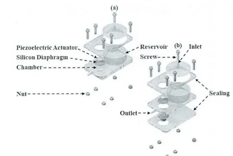
Sealing Outlet - - ►Fig. 1. Exploded view of the micropunips, (a) SDM, (b) BDM.
and electrical effects on flow rates. In addition, new
designs have been proposed by different
researchers, but there are no studies supporting each other.
In this study, we fabricated two PZT based novel micropunips that can be used in a wide range of areas such as mechanical, energy and biomedical applications. The novelty o f this study was that the BDM (Bi-diaphragm Micropump) and SDM (Single Diaphragm Micropump) had a fixed reservoir near the chamber to achieve portable and controllable features. Another geometric novelty was that the BDM consisted o f a chamber sandwiched between two diaphragms actuated by two piezoelectric actuators at the same time to achieve high flow rate. According to literature survey, there is no similar micropump geometry in the presented studies. In order to compare the performance o f the BDM, we
fabricated the SDM with same geometric
parameters and material. All the structure elements o f the micropumps were selected as biocompatible. Therefore, the silicon was chosen as a diaphragm in these micropunips, and the PMMA was used to fabricate the chamber, nozzle/diffuser elements and
reservoir. Profilometer, Scanning Electron
Microscopy and Field Emission Microscopy were used for surface roughness characteristics o f the fabricated micropunips. Drop shape analysis was used to test hydrophobic or hydrophilic behavior of the PMMA material. At last, a tensile test was applied for elastic behavior o f the silicon diaphragm. Consequently, experimental flow rates were measured and it was shown that BDM had higher flow rates at all frequency and voltage levels.
2. M
aterialsandM
ethods2.1 Micropump
Design
and
Working
Principle
The structure of piezoelectric micropumps is shown
in Fig. 1. These micropunips consist o f fluid reservoir, chamber, nozzle/diffuser elements, silicon diaphragm and piezoelectric actuator. We fabricated the chamber, nozzle/diffuser and fluid reservoir in the clean room by using the Objet260 Connex3 printer. The material o f these elements was PMMA. On the other hand, in this study, piezoelectric coated brass disks were used, which can be
available commercially. Moreover, silicon
diaphragm was the separator layer of piezoelectric actuator with water. To study the characteristics of
the silicon diaphragm “Tensile Test” was
performed. In addition, the silicon diaphragm properties can be summarized as; Young's modulus (162 GPa), Poisson's ratio (0.22) and density (2329 kg/m3) respectively. The optimum nozzle diffuser divergence angle was reported 10-degrees (Singh el
al., 2015). Therefore, in this study the nozzle/diffuser divergence angle was chosen 10- degrees. Inlet and outlet diameters o f nozzle- diffuser elements were designed to be 0.2 mm and 2 mm, respectively. The height o f the reservoir and radius were 20 mm and 25 mm, respectively. The
geometric parameters o f the micropunips
components were given in the Table 1.
As shown in Fig. 1, the physical parameters o f the two micropunips were exactly equal. The only difference between these two micropunips was the number o f diaphragm and piezoelectric actuators. Thus, that in the SDM, in the upper part o f the chamber, there was a silicon diaphragm and a piezoelectric actuator. While in the BDM, two silicon diaphragm and two piezoelectric actuators
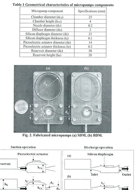
were used. Figure 2 shows the prototype
micropunips fabricated by PMMA material. Figure 3 shows the working principle o f the proposed micropunips. The working principle and displacement measurement of the represented micropunips in this study were similar to the studies by Mohith et al. (2019); Yildiz el al. (2019) and Dereshgi el al. (2019). Applying alternative voltage
H. Asadi Dereshgi etal. / JAFM, Vol. 13, No. 2, pp. 401-412, 2020.
Tabic 1 Geometrical characteristics of micropumps components
Micropump component Specifications (mm)
Chamber diameter (dcii) 25
Chamber height (hen) 4
Nozzle diameter (dsi) 0.2
Diffuser diameter (do) 2
Silicon diaphragm diameter (ds) 25
Silicon diaphragm thickness (ts) 0.1
Piezoelectric actuator diameter (dp) 14
Piezoelectric actuator thickness (tp) 0.2
Reservoir diameter (dp) 50
Reservoir height (Ii r) 20
Fig. 2. Fabricated micropumps (a) SDM, (b) BDM.
Suction operation Discharge operation
Fig. 3. Working principle of the proposed micropumps, (a) SDM, (b) BDM.
causes piezoelectric deformation that is called reverse piezoelectric effect. The piezoelectric displacement rate depends on the amount o f applied
voltage and its direction. The diaphragm
displacement in piezoelectric micropumps causes the pump stroke to increase and decrease periodically. Thus, the fluid is delivered from the inlet to the outlet. The flow is assumed to be Newtonian, steady, incompressible and fluid with constant properties. The mesh convergence method was used by COMSOL Multiphysics 4.3 to obtain required displacement amplitude o f the diaphragm where the values were saturated. The working
principle o f piezoelectric actuators include two stages, namely, the discharge and the suction. By applying the sinusoidal voltage, the diaphragm vibrates. In the positive half cycle o f the sinusoidal voltage, the diaphragm bends upwards, and in this situation, the liquid suction was earned out from the reservoir to the chamber. In the negative half-cycle o f the sinusoidal voltage, the diaphragm bends downward and the discharge o f fluid front the chamber takes place. In this study, to piezoelectric o f both micropumps the same voltage and frequencies were applied. However, the sinusoidal voltage was applied with 180-degrecs phase shift to
H. Asadi Dereshgi et al. / JAFM , Vol. 13, No. 2, pp. 401-412, 2020.
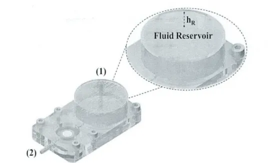
Fig. 4. The effect of reservoir height on flow rate.
BDM’s piezoelectric actuators. The phase shift increased the suction and discharge force o f the BDM compared to the SDM. In other words, increasing discharge and suction force resulted in an increase in net flow rate. The results obtained from the micropumps are presented in Section 3.
2.2 Micropunip Calibration and Flow Test
In this study micropumps and fluid reservoir were fabricated as adjacent as shown in Fig. 4. Each micropump (SDM and BDM) had a fluid reservoir. The micropump chamber was connected with reservoir through a nozzle/diffuser element. The nozzle/diffuser elements did not have moving components. Therefore, when the voltage was not applied to the piezoelectric (inactive status), always a constant amount o f flow rate was obtained due to water height in reservoir. Therefore, hydrostatic pressure gradient occurred from reservoir (pointed as 1 in Fig. (4)) to outlet (2) o f micro pump and head loss caused by a sudden increase or decrease could be considered in theoretical calculation. While energy equation was applied for the one dimensional control volume for not pumping, extended Bernoulli equation is expressed in Eq. (1);
+ AI,lolal
(1)
P: Fluid pressure, v: Fluid Velocity, r: Height of
streamline, p: Fluid density, g: Gravity constant.
“Pi" and “Pi" arc atmospheric pressures, “vi” and “z2" are equal to zero. Finally, “AhiotaP total head
loss is consisted o f friction (j) and minor losses,
2
A ' h o t a l = ( f ^ + W V— (2)
D 2g
o f “K.” have been studied for Nozzle and diffusers (Stcmme el al., 1993; Singhal et al., 2004). Based on literature studies, total head loss was obtained with Eq. (2). Additionally, the theoretical flow rates were calculated according to the liquid height in the reservoir. Then theoretical flow rates are confirmed by the experimental data collected on inactive status. In order to determine the flow rates caused only by PZT, the experiments were repeated while the piezo on active status. The flow tests for SDM and BDM micropumps were performed on active and inactive status and actual piezo flow rates were determined subtracting from each other.
Water has been used as a working fluid in the investigation. In experiments, the fluid (water) was at ambient conditions (20.0 - 21.0 0 C). Mass flow measurement has been done by both from precision glass syringe and measuring water weight collected on a digital balance (Mettler Toledo ML200T). All measurements were repeated at least three times to improve reliability o f the flow tests. The analyzed
measurement uncertainties were calculated
according to the method presented by Kline and McClintock (Holman et al., 2001). Standard deviation o f flow rates was calculated and random errors were determined by multiplying by 1.95 for 95% confidence level. Standard uncertainties of measured parameters were: 21 0 C ± 0.6 for inlet temperature; 60 s ± 0.0003 for time interval; 10 g ± 0.01 for digital balance and 999 kg/m3 ± 0.1 for density o f water. As a result, the highest uncertainties o f volume and mass flow rate were calculated for tests under conducted 5 V and 5 Hz as + 2.2 % and + 2.3 % respectively.
3. Re s u l t s
where, “L” is the length, "D" is the diameter and “K” is the loss coefficient. In the literature, values
3.1 Drop Shape Analysis (DSA)
Surface roughness, porosity and hydrophilicity are important factors in fluid mechanics because they
H. Asadi Dereshgi etal. / JAFM, Vol. 13, No. 2, pp. 401-412, 2020.
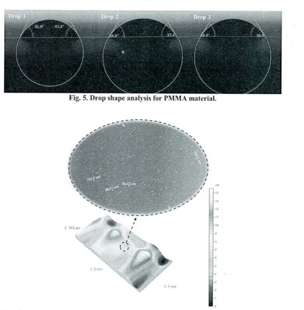
Fig. 5. Drop shape analysis for PMMA material.
Fig. 6. FSEM and profilometer image of PMMA for porosity and roughness measurements.
can affect interactions between fluid and solid. The nozzle /diffuser elements, the chamber and the fluid reservoir were fabricated from PMMA. Drop shape analysis (DSA) was performed to determine the contact angle front the shadow image o f a sessile drop and the surface tension or interfacial tension from the shadow image o f a pendant drop. Drop shape analysis (DSA) was performed by KRUSS (DSA100M, KRUSS GmbH, Germany) measuring instruments with a sensitivity of 0.05°. This test was repeated 3 times at 20°C. The average o f performed analysis o f contact angle showed that a drop water was 58.36° (±2.85°). The results showed that the PMMA used in this study was hydrophilic and usual no-slip boundary condition was still valid. In other words, there is no self-filling and fluid flow due to the hydrophilic properties in flow tests. The DSA results are shown in Fig. 5.
3.2 Microscopic Image Investigation
Microscopic images were used to evaluate surface properties o f micropump due to the possibility of testing with biological fluids in the future studies.
As described in Section 2, the nozzle /diffuser elements, the chamber and the fluid reservoir were fabricated in clean room by the rapid prototyping device (Objet260 Connex3) with 16-micron layer resolution. Therefore, we examined a piece o f the PMMA material in the field-emission scanning
electron microscope (FSEM). Moreover,
profilometer was used to visualize surface porosity and roughness characteristics o f PMMA surface. In most cases, porosity and roughness are undesirable while, depending on the type o f application, pore structures on the flow surface are preferred.
As shown in Fig. 6, undesired porosity was in the nanometer size, flow surface was completely assumed as smooth surface. In addition, the mean roughness was measured as 383.4 A. Thereby, the undesired particles and the amount o f the roughness o f the PMMA surface have no effect on the fluid behavior o f the chamber or the fluid in the nozzle/diffuser elements.
Another important issue was to determine the inlet and outlet diameters o f the nozzle/diffuser elements
H. Asadi Dereshgi el al. / JAFM , Vol. 13, No. 2, pp. 401-412, 2020.
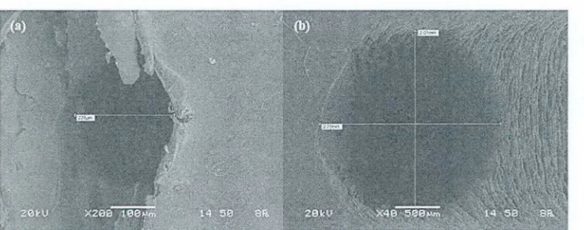
Fig. 7. A (SEM) images of PMMA (a) Nozzle/ diffuser inlet (h) Nozzle/ diffuser outlet.
in terms o f the reliability of the calibration. Hydraulic diameters were designed as 0.2 mm and 2 mm, and SEM was used to determine the exact sizes after fabrication. Figure 7 shows the image of the Scanning Electron Microscope (SEM) of (a) water inlet and (b) outlet sections to these nozzle/diffuser elements. The water in the chamber is entered to the nozzle/ diffuser with a hydraulic diameter o f 257.07 pm. Moreover, the diameter o f nozzle/ diffuser clement was 2061.91 pm at the moment o f full water discharge. This causes at the discharge moment, the pressure to increase and the velocity to decrease.
3.3 Simulation Results of the Diaphragm
Displacements
The piezoelectric crystal was used in both micropumps with a diameter o f 14 mm and 0.2 mm thickness as an actuator. Silicon was also used as a diaphragm with a diameter o f 25 mm and a thickness o f 0.1 mm on each silicon diaphragm a piezoelectric was clamped. The voltage caused a
vibration in the piezoelectric actuator. The
piezoelectric edges were fully clamped on the
silicon diaphragm. Therefore, the horizontal
vibration was converted to the vertical vibration. The voltage determines the vibration amplitude and the frequency specifies the number o f vibrations. The presented micropumps in this study were designed as potential candidate for biomedical applications which require relatively low level of driving voltages and frequencies. Thus, the driving voltage values were set to 5 V to 45 V by 5 V increments and the frequencies were 5 Hz, 10 Hz, 15 Hz and 20 Hz. Diaphragm displacement calculations were earned out by finite element methods. The Material, geometric shape and
applied sinusoidal voltage were same in
diaphragms, because o f this diaphragm
displacement was the same in SDM and BDM. Figure 8 shows the simulation results o f diaphragm displacements at the moment of water discharge from the chamber. It shows that the increase in
voltage increased displacement. Additionally,
increasing the frequency reduced displacement. Thus, the piezoelectric vertical vibration or displacement mode depends on the applied AC voltage behavior. The piezoelectric displacement is
transmitted exactly to the diaphragm because of being tangent. Finally, the diaphragm displacement causes the pressure difference in the chamber, and it causes fluid transport from reservoir to chamber and chamber to outlet. The net flow rate values of the proposed micropumps were shown in Section 3.4. However, the displacement results have 99% liner behavior. The maximum displacement was obtained 4.097 tun in 45 V and 5 Hz. 4.5 4 •g 3.5 ~ 3 5 2.5 P 2 rs 3.1.5 a i 0.5 0 R* - 0.1965 ti' = (1.9978 K-’ =0.9976 = 0.9977 - • 51!/, -D lflllz -A-IS1U .0-2011/ Id 20 30 40 50 Voltage (V)
Fig. 8. Diaphragm displacement results at 5
Hz, 10 Hz, 15 Hz and 20 Hz.
3.4 Experimental Results of the Flow Rates
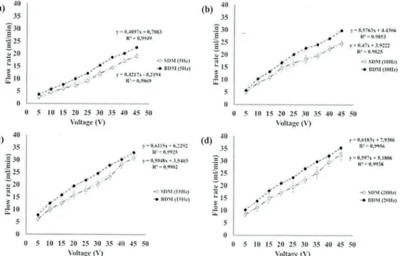
At the mentioned voltages and frequencies, we measured the net How rate o f the micropumps. Figure 9 shows the results o f flow rates o f SDM and BDM tnicropumps. The amplitude o f the
diaphragm displacement was increased by
increasing the voltage. The frequency increase led to a decrease in displacement at per stroke. However, due to the increase in the number o f vibrations, which is the total number o f strokes, the flow rates in both micropump increased. There was linear correlation in Fig. 9, linear behavior o f each pump at different driving frequencies were given according to experimental measurement. At all frequencies, the slope o f the BDM was higher. So, with increasing voltage, the flow rates increase was higher compared to SDM. The maximum flow rates obtained for SDM and BDM in 45 V and 20 Hz were 32.58 ml/min and 35.4 ml/min respectively.
H. Asadi Dereshgi et al. / JAFM , Vol. 13, No. 2, pp. 401-412, 2020.
(a)
40 35 3 30 | 25 r 20 > 15 ! io 5 10 15 20 25 30 35 40 45 50 Voltage (V)(C)
40 35 . f 30 E ~ 2 5E «T 20 u | 5 rr 10 5 10 15 20 25 30 35 40 45 50 Voltage (V)(b)
v = 0,4897s + 0,7083 R 1 = 0 ,9 9 4 9 ^ 0 " -0 SD.M (5llz) >" - • R D M <51 fz ) V ” 0 .4 2 1 7 * -0 ,2 1 9 4 R ?» 0.9 869 40 35 • f 30 E s 25 2 20 a Z 15 ! io 5 0 y - 0.6 ll5 i + 6.2292 R1 - 0.9925 y = 0,5948\ + 3.5403 Rl = 0,9902 -O-SDM (I5llz) -♦ BOM (15liz> ( d ) 40 35 £ 3 0 ~ 25 c sT 20>15
I *0 5 0 M-* y « 0.5763* + 4.4306 K5 * 0.9853 v = 0.47x + 3.9222 R*« 0.9825 -C SDM (Kill/) - • BOM (Wife) 5 10 15 20 25 30 35 40 45 50 Voltage (V) , 4 . ■" 0.6183* + 7,9306 y = 0.597x + 5.1806 K* ■» 0,9938 SDM (201!/) - • BOM (20tfe) 10 15 20 25 30 35 40 45 50 Voltage (V)Fig. 9. Maximum flow rate results at (a) 5 Hz, (b) 10 Hz, (c) 15 Hz and (d) 20 Hz.
4.
D
iscussionIn this study, the performance o f two novel
niicropumps was studied in the same
experimental conditions. The only difference in the SDM and BDM was the number o f vibrating diaphragms. Based on the results obtained in Section 3, the BDM flow rate compared to SDM at 5 Hz, 10 Hz, 15 Hz and 20 Hz were increased
to 22%, 16.39%, 15.97% and 15.19%
respectively. The water weight inside the
chamber prevented moving the bottom
diaphragm o f the BDM. I f the water weight force was not in the opposite direction o f the bottom diaphragm force, we would expect a significant increase in the flow rate o f the BDM design. As an important advantage, in the daily usage BDM design gives an opportunity to use both side facing upwards without losing the flow rate when the reservoir is closed to the atmosphere and adjustable according to the nozzle elements.
4.1 Comparison with the State of the Art
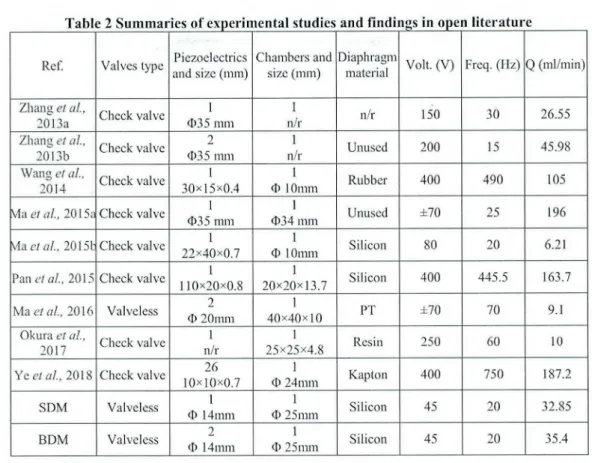
The presented micropumps in this study were designed as potential candidate for biomedical applications which require relatively low level of driving voltages and frequencies. Insulin delivery or other fluidic drugs dispersion into the human body might be possible by these micropump designs. Table 2 shows the similar studies about the piezoelectric micropumps and their flow rates during the last 10 years.
These studies include the micropumps with larger piezoelectric actuator and larger chambers. In addition, unlike our designs, they used higher voltages and frequencies. Thereby, some o f the studies created higher flow rates.
When the studies in Table 2 were investigated, it was seen that Zhang et al. (2013a & 2013b), Pan
el al. (2015), Okura et al. (2017) and Ye et al.
(2018) used very high AC voltages between 150 V and 400 V. These driving AC voltage levels can be considered very high and risky when the micropumps were considered to be used near the body surface for biomedical related applications. In addition, all the studies mentioned above used a check-valve in their designs. In the study by Ma
et al. (2015a), they used 70 V AC voltage at 25
Hz and they measured 196 ml/min net flow rate. In their study, the diameter of PZT actuator was 2.5 time larger than we used in SDM and BDM micropump. Thereby, the maximum flow rate was almost 2.5 times higher according to our results. In fact, they did not show the calibration flow rate calculation and subtraction from the net flow rate values when the driving voltage was zero (at static condition). In addition, Ma et al. (2015b & 2016) used relatively low driving voltages (70-80 V) and frequency (20 Hz). But in these studies, they measured low net flow rates, i.e. 6.21 ml/min and 9 .1 ml/min respectively. The most similar study to this presented study was done by Ma et al. (2016) with a valveless geometry. Even though they used similar size PZT actuator, their chamber height was 2.5 times bigger than our SDM and BDM micropump chambers. Thereby, they measured 2.5 times lower flow rates as compatible with the literature because o f the chamber height effect (Lin
el al., 2006; Ni e l al , 2010).
When these studies arc considered in general, we see that we have obtained a high flow rate at lower voltage and frequency values by using an integrated reservoir with SDM and BDM designs.
H. A sadi D ercshgi
el al.
IJAFM,
Vol. 13, N o. 2, pp. 401-412, 2020.Table 2 Summaries of experimental studies and findings in open literature
Ref. Valves type Piezoelectrics
and size (mm)
Chambers and size (mm)
Diaphragm
material Volt. (V) Freq. (Hz) Q (ml/min)
Zhang et al.,
2013a Check valve
I <1)35 mm 1 n/r n/r 150 30 26.55 Zhang et al, 2013b Check valve 2 035 mm 1 n/r Unused 200 15 45.98 Wang et al., 2014 Check valve i 30x15x0.4 i O 10mm Rubber 400 490 105
Ma e ta l, 2015a Check valve 1
03 5 mm
1
03 4 mm Unused ±70 25 196
Via et al, 20151: Check valve 1
22x40x0.7
1
O 10mm Silicon 80 20 6.21
Pan et al, 2015 Check valve 1
110x20x0.8 1 20x20x13.7 Silicon 400 445.5 163.7 Ma e ta l, 2016 Valveless 2 O 20mm 1 40x40x10 PT ±70 70 9.1 Okura et al, 2017 Check valve 1 n/r 1 25x25x4.8 Resin 250 60 10 Y e e ta l, 2018 Check valve 26 10x10x0.7 1 O 24 mm Kapton 400 750 187.2 SDM Valveless 1 O 14mm 1 O 25 mm Silicon 45 20 32.85 BDM Valveless 2 O 14mm 1 O 25mm Silicon 45 20 35.4
4.2
Biomedical
Considerations
of
Micropumps
Micropumps are one o f the most important MEMS devices that can play an important role in drug delivering. The micropumps that are designed for the purpose o f drug delivery should meet the requirements and basic terms, including drug biocompatibility, actuation safety, desired and controllable flow rate, small chip size and low power consumption. Biocompatibility is a very important key parameter that is necessarily considered for drug delivery micropumps (Lins et
a l, 2001; Grayson et al.. 2004). On the other hand,
the micropumps used for the purpose of drug delivery in the human body should be selected so that they had biocompatibility and biostability (Anderson et al., 1999). Moreover, the implanted micropump based drug delivery system should have
sufficient resistance to the physiological
environment and the adverse impact o f surrounding tissues (Anderson et a l, 2013).
Silicon is a good biocompatible material. It is one of the materials which has been much preferred in recent years’ biomedical studies. However, the process o f using polymers in medical fields is widespread and suitable for human implantation. Additionally, Polymer materials such as PMMA, PDMS, and SU-8 photo resist have better
biocompatibility and are more preferred in
micropump based drug delivery (Nisar et a l, 2008). Tt might be concluded that micropump designs in
this study were compatible with medical
considerations.
5. C
onclusionThe puiposc o f this study was to investigate the effect o f electro-mechanical factors on the flow rate. SDM and BDM were two novel designs that proposed in this study. The effect o f voltage and frequency was clearly shown on the flow rates. The embedded reservoir combined with the chambers were presented promising results. Materials were biocompatible which considered as a crucial factor for biomedical applications. The flow rates were comparable with the state-of-the-art literature. The SDM flow rate was increased by 37.73% at 10 Hz, 47% at 15 Hz and 52.06% at 20 Hz compared to 5 Hz reference excitation frequency. Moreover, as for BDM flow rates, the increment rates were 33.70%, 42.90% and 47.93% for the same frequencies. Both SDM and BDM flow rates were linearly increased as a function o f voltages at all frequencies. All in all, experimental results showed that our novel BDM design will be a good candidate especially for biomedical applications, such as drug delivery, blood transport after more investigations.
A
cknowledgementsThis study was supported by Scientific Research Projects Unit o f Sakaiya University o f Applied Sciences (Project Number: 2017-50-02-026).
R
eferencesAfrasiab, H., M. Movahhedy and A. Assempour (2011). Proposal of a new design for valveless
H. Asadi D ereshgi
etal.
/JAFM,
Vol. 13, N o. 2, pp. 401-412, 2020.micropumps. Scientia Iranica 18(6), 1261- 1266.
Amirouche, F., Y. Zhou and T. Johnson (2009). Current micropump technologies and their
biomedical applications. Microsystem
Technologies 15(5), 647-666.
Anderson, J. M. (1999). Issues and perspectives on
the biocompatibility and immunotoxicity
evaluation of implanted controlled release systems. Journal o f Controlled Release 57(2),
107-113.
Anderson, J. M. (2013). Inflammation, Wound
Healing, and the Foreign-Body Response. In: Biomaterials science. Academic Press, USA.
Cazorla, P. H., O. Fuchs, M. Cochet, S. Maubert, G. L. Rhun, Y. Fouillet and E. Defay (2016). A low voltage silicon micro-pump based on piezoelectric thin films. Sensors and Actuators
A: Physical 250, 35-39.
Chang, H. T., C. Y. Lee and C. Y. Wen (2006). Design and modeling o f electromagnetic actuator in mems-based valvcless impedance pump. Microsystem Technologies 13(11-12), 1615-1622.
Derakhshan, S., B. Bcigzadeh, M. Rashidi and H.
Pourrahmani (2019). Performance
Improvement and Two-Phase Flow Study o f a Piezoelectric Micropump with Tesla Nozzle- Diffuser Microvalves. Journal o f Applied Fluid
Mechanics 12(2), 341-350.
Dereshgi, H. A. (2016, November). Design o f novel micro-pumps for mechatronic applications. In
4th Int. Symposium on Innovative Technologies in Engineering and Science, Antalya, Turkey.
Dereshgi, H. A. and M. Z. Yildiz (2018a). A novel micropump design: Investigation o f the voltage effect on the net flow rate. Sakarya University
Journal o f Science 22(4), 1152-1156.
Dereshgi, H. A. and M. Z. Yildiz (2018b). Investigation o f electro-mechanical factors effecting piezoelectric actuator for valveless
micropump characteristics. Journal o f
Engineering Science and Technology 13(9),
2843-2856.
Dereshgi, H. A. and M. Z. Yildiz (2019, April). Numerical Study o f Novel MEMS-Based Valveless Piezoelectric Micropumps in the Range o f Low Voltages and Frequencies.
Scientific Meeting on Electrical-Electronics &
Biomedical Engineering and Computer
Science (EBBT), Istanbul, Turkey.
Dong, J. S., R. G. Liu, W. S. Liu, Q. Q. Chen, Y. Yang, Y. Wu, Z. G. Yang and B. S. Lin (2017). Design o f a piezoelectric pump with dual vibrators. Sensors and Actuators A:
Physical 251, 165-172.
Ehsani, A. and A. Nejat (2017). Conceptual design and performance analysis o f a novel flexible- valve micropump using magneto-fluid-solid
interaction. Smart Materials and Structures 26(5), 055036.
Farshchi Yazdi, S. A. F., A. Corigliano and R. Ardito (2019). 3-D Design and Simulation o f a
Piezoelectric Micropump. Micromachines
10(4), 259.
Grayson, A., R. Shawgo, A. Johnson, N. Flynn, Y. Li, M. Cima and R. Langer (2004). A BioMEMS Review: MEMS Technology for
Physiologically Integrated Devices.
Proceedings o f the IEEE 92(1), 6-21.
Ifamid, N. A., B. Y. Majlis, J. Yunas, A. R. Syafeeza, Y. C. Wong and M. Ibrahim (2016). A stack bonded thermo-pneumatic micro-pump utilizing polyimidc based actuator membrane
for biomedical applications. Microsystem
Technologies 23(9), 4037-4043.
Holman, J. P. and W. J. Gajda (2001). Experimental
methods fo r engineers. McGraw-Hill, New
York, USA.
Hsu, Y. C., S. J. Lin and C. C. Hou (2007). Development o f peristaltic antithrombogenic micropumps for in vitro and ex vivo blood transportation tests. Microsystem Technologies 14(1),31-41.
Johnson, D. and D. Borkholder (2016). Towards an Implantable, Low Flow Micropump That Uses
No Power in the Blocked-Flow State.
Micromachines 7(6), 99.
Kawun, P., S. Leahy and Y. Lai (2016). A thin
PDMS nozzlc/dilTuscr micropump for
biomedical applications. Sensors and
Actuators A: Physical 249, 149-154.
Kolahdouz, L. M., K. Mohammadzadeh and E.
Shirani (2014). Performance of
piezoclcclrically actuated micropump with
different driving voltage shapes and
frequencies. Scientia Iranica. Transaction B,
Mechanical Engineering 21(5), 1635-1642.
Lc, S. and H. Ilegab (2017). Investigation o f a multistage micro gas compressor cascaded in series for increase pressure rise. Sensors and
Actuators A: Physical 256, 66-76.
Lee, C. Y., P. C. Chou, L. M. Fu and J. H. Zhong (2012, September). Design and fabrication o f an electromagnetic pump for microfluidic applications. IEEE Symposium on Industrial
Electronics and Applications, Bandung, Indonesia.
Lin, Q., B. Yang, J. Xie and Y. C. Tai (2006). Dynamic simulation o f a peristaltic micropump considering coupled fluid flow and structural motion. Journal o f Micromechanics and
Microengineering 17(2), 220-228.
Lins, G. and L. Skogberg (2001). An investigation
o f insulin pump therapy and evaluation o f using a micropump in a future insulin pump.
M.S. thesis, KTH, Stockholm, Sweden. Ma, H. K., R. H. Chen and Y. II. Hsu (2015a).
H. Asadi Dercshgi el al. / JAFM , Vol. 13, No. 2, pp. 401-412, 2020.
Development o f a piezoelectric-driven
miniature pump for biomedical applications.
Sensors and Actuators A: Physical 234, 23-33.
Ma, H. K„ R. H. Chen, N. S. Yu and Y. H. Hsu (2016). A miniature circular pump with a
piezoelectric bimorph and a disposable
chamber for biomedical applications. Sensors
and Actuators A: Physical 251,108-118.
Ma, H. K„ W. F. Luo and J. Y. Lin (2015b). Development o f a piezoelectric micropump with novel separable design for medical
applications. Sensors and Actuators A:
Physical 236, 57-66.
Maillefer, D., S. Gamper, B. Frehner, P. Balrner, H. V. Lintel and P. Renaud (2001). A high- performance silicon micropump for disposable drug delivery systems. 14th IEEE International
Conference on Micro Electro Mechanical Systems (Cat. No.0lCH37090).
Mohammadzadeh, K., E. M. Kolahdouz, E. Shirani and M. B. Shafii (2013). Numerical study on the performance of Tesla type microvalvc in a valveless micropump in the range o f low frequencies. Journal o f Micro-Bio Robotics 8(3-4), 145-159.
Mohith, S., P. N. Karanth and S. M. Kulkami
(2019). Recent trends in mechanical
micropumps and their applications: A review.
Mechatronics 60, 34-55.
Ni, J., F. Huang, B. Wang, B. Li and Q. Lin (2010). A planar PDMS micropump using in-contact minimized-leakage check valves. Journal o f
Micromechanics and Microengineering 20(9),
095033.
Nisar, A., N. Afzulpurkar, B. Mahaisavariya and A.
Tuantranont (2008). MEMS-based
micropumps in drug delivery and biomedical
applications. Sensors and Actuators B:
Chemical 130(2), 917-942.
Okura, N., Y. Nakashoji, T. Koshirogane, M. Kondo, Y. Tanaka, K. Inoue and M. Hashimoto (2017). A compact and facile microfluidic droplet creation device using a piezoelectric diaphragm micropump for droplet digital PCR platforms. Electrophoresis 38(20), 2666-2672.
Pabst, O., J. Perelaer, E. Beckert, U. S. Schubert, R. Eberhardt and A. Tunnermann (2013). All inkjet-printed piezoelectric polymer actuators:
Characterization and applications for
micropumps in lab-on-a-chip systems. Organic
Electronics 14(12), 3423-3429.
Pabst, O., S. Holzer, E. Beckert, J. Perelaer, U. S. Schubert, R. Eberhardt and A. Tunnermann (2014). Inkjet printed micropump actuator based on piezoelectric polymers: Device performance and morphology studies. Organic
Electronics 15(11), 3306-3315.
Pan, Q. S., L. G. He, F. S. Huang, X. Y. Wang and Z. IT. Feng (2015). Piezoelectric micropump
using dual-frequency drive. Sensors and
Actuators A: Physical 229, 86-93.
Rcvathi, S. and R. Padmanabhan (2018). Design and Development of Piezoelectric Composite-
Based Micropump. Journal o f
Microelectromechanical Systems 27(6), 11 OS-
1113.
Robertson, J. M., R. X. Rodriguez, L. R. Holmes, P. T. Mather and E. D. Wetzel (2016). Thermally driven microfluidic pumping via reversible shape memory polymers. Smart Materials and
Structures 25(8), 085043.
Sardar, V. B., N. R. Rajhans, A. Pathak and T. Prabhu (2016). Developments in silicone material for biomedical applications- A review.
14tli International Conference on Humanizing Work and Work Environment HIVJVE.
Schomburg, W. K., J. Vollnter, B. Bustgens, J. Fahrenberg, H. Hein and W. Menz (1994). Microfluidic components in LIGA technique.
Journal o f Micromeclianics and
Microengineering 4(4), 186-191.
Shaegh, S. A. M., Z. Wang, S. H. Ng, R. Wu, H. T. Nguyen, L. C. Z. Chan, A. G. G. Toh and Z. Wang (2015). Plug-and-play microvalve and
micropump for rapid integration with
microfluidic chips. Microfluidics and
Nanofluidics 19(3), 557-564.
Shoji, E. (2016). Fabrication o f a diaphragm micropump system utilizing the ionomer-based polymer actuator. Sensors and Actuators B:
Chemical 237, 660-665.
Sim, W. Y., H. J. Yoon, O. C. Jeong and S. S. Yang (2003) . A phase-change type micropump with
aluminum flap valves. Journal o f
Micromechanics and Microengineering 13(2),
286-294.
Singh, S., N. Kumar, D. George and A. Sen (2015).
Analytical modeling, simulations and
experimental studies of a PZT actuated planar valveless PDMS micropump. Sensors and
Actuators A: Physical 225, 81-94.
Singhal, V., S. V. Garimella and J. Y. Murthy (2004) . Low Reynolds number flow through
nozzle-diffuser elements in valveless
micropumps. Sensors and Actuators A:
Physical 113(2), 226-235.
Smits, J. G. and N. V. Vitafin (1984). Piezo
electrical micropump. European patent
EP0134614.
Stemme, E. and G. Stemme (1993). A valveless diffuser/nozzle-bascd fluid pump. Sensors and
Actuators A: physical 39(2), 159-167.
Tanaka, Y., Y. Noguchi, Y. Yalikun and N. Kamamichi (2017). Earthworm muscle driven bio-micropump. Sensors and Actuators B:
Chemical 242, 1186-1192.
Tay, F. E. H. (2002). Microfluidics and bioMEMS
H. A sadi Deresligi e ta l. / J A F M , V ol. 13, N o. 2, pp. 401-412, 2020.
Publishers, London, United Kingdom.
Teymoori, M. M. and E. Abbaspour-Sani (2005). Design and simulation o f a novel electrostatic peristaltic micromachined pump for drug delivery applications. Sensors and Actuators
A: Physical 117(2), 222-229.
Wang, J., Y. Liu, Y. Shen, S. Chen and Z. Yang (2016). A Resonant Piezoelectric Diaphragm
Pump Transferring Gas with Compact
Structure. Micromachines 7(12), 219.
Wang, X. Y., Y. T. Ma, G. Y. Yan, D. Huang and
Z. H. Feng (2014). High flow-rate
piezoelectric micropump with two fixed ends polydimethylsiloxane valves and compressible spaces. Sensors and Actuators A: Phvsical 218, 94-104.
Wang, Y. N. and L. M. Fu (2018). Micropumps and
biomedical applications - A review.
Microelectronic Engineering 195, 121-138.
Ye, Y., J. Chen, Y. J. Ren and Z. H. Feng (2018). Valve improvement for high flow rate
piezoelectric pump with PDMS film valves.
Sensors and Actuators A: Physical 283, 245-
253.
Yildiz, M. Z. and H. A. Deresligi (2019). Design of PZT micropumps for biomedical applications:
Glaucoma treatment. Journal o f Engg.
Research 7(2), 226-241.
Zhang, Z., J. Kan, G. Cheng, H. Wang and Y. Jiang (2013a). A piezoelectric micropump with an integrated sensor based on space-division
multiplexing. Sensors and Actuators A:
Physical 203, 29-36.
Zhang, Z., J. Kan, S. Wang, H. Wang, J. Wen and Z. Ma (2013b). Flow rate self-sensing o f a pump with double piezoelectric actuators.
Mechanical Systems and Signal Processing
41(1-2), 639-648.
Zhou, Y. and F. Amirouche (2011). An
Eleclromagnetically-Actuated All-PDMS
Valveless Micropump for Drug Delivery.