Commun. Fac. Sci. Univ. Ank. Series A2-A3 V.55(1) pp 1-15 (2013)
*This work is a part of the project, Adaptive Speed Control of Electric Vecihles, supported by grants from the Office of Scientific Research Projects of Ankara University (Project Number: 12B 4343 016).
ADAPTIVE CRUISE CONTROL SYSTEM AND ITS IMPLEMENTATION*
MELİH SARP, ALİCAN TOPÇU AND HAKKI ALPARSLAN ILGIN Ankara University, Faculty of Engineering, Electrical and Electronics Eng. Dept.,
06830, Gölbaşı, Ankara, TURKEY
(Received Nov.12, 2012; Accepted April 4, 2013)
ABSTRACT
An adaptive cruise control (ACC) system based on PID Controller for vehicles with electric motor is developed. Modeling of an electric motor is presented for analyzing the unit step response of the system. The effects of integral and derivative control actions on the system performance are investigated and results are illustrated using Simulink.
KEYWORDS: Adaptive Cruise Control, Cruise Control INTRODUCTION
Although Electrical vehicles face several limitations, such as battery cost, weight, disposal, few battery commercial recharging stations, they are becoming more popular and demanding recently thanks to their eco- and budget- friendly fuel systems. Electric cars have several benefits compared to internal combustion engine automobiles, including a significant reduction of air pollution since they are propelled by one electric motor using electrical energy stored in batteries. However, the number of vehicles on the highways is increasing rapidly and urban highways in most major cities are overcrowded. This situation brings about a need to use highways more efficiently. In addition, involving reaction time, delays and human errors, human drivers also affect the traffic flow adversely. One possible way to solve these problems is to remove human involvement as possible from the system through computer control. Driver behavior in vehicle has engaged attention of researchers since the early 50s [1]. According to a research conducted by General Motors technical center, the typical human reaction time in driving is about 1.5 sec [1]. This reaction time can be removed completely thanks to the introduction of computers. In addition, it is expected that vehicle and highway automation system reduce the risk of accidents, improve safety, increase highway flow capacity, and reduce fuel consumption [2]. The automation considered in this study is based on the so-called Adaptive Cruise Control (ACC) which is applied to an electric car.
M. SARP, A. TOPÇU AND H. A. ILGIN 2
ACC is a driver assistance system that performs some undesirable routines of driving tasks on the behalf of human drivers. In such a system, vehicle acceleration is controlled by a computer and steering is under manual control. The distance between host vehicle and lead vehicle is measured through the sensor located on-board of the vehicle. Based on measurements, computer sends the appropriate commands to accelerate or decelerate the vehicle.
The ACC system consists of two states which are “cruising state” and “vehicle following state”. In the cruising state, the velocity set by the driver is maintained under no lead vehicle situation, while in vehicle following state, the safe distance from the lead vehicle is maintained by adapting to its velocity.
In this study, the ACC vehicle following system mostly based on PID controller is presented. The transient response of the system is analyzed in order to investigate the stability of the system. The effects of the PID parameters on the system are illustrated to demonstrate the unit step response of the system.
1 MODELING OF DC MOTORS
1.1 EQUIVALENT CIRCUIT AND ELECTROMAGNETIC TORQUE The equivalent circuit of a DC armature basically consists of the armature winding resistance Ra, a self-inductance La, and an induced emf. [3] In the case of a
motor whose equivalent circuit is shown in Figure 1.1. , the input is electrical energy and the output is the mechanical energy, with air gap torque of Te at a rotational
speed of wm. The terminal relationship is written as
𝑣 = 𝑒 + 𝑅𝑎𝑖𝑎+ 𝐿𝑎 𝑑𝑖𝑎
𝑑𝑡 (1.1)
In steady state, since the armature current doesn’t change, which means the rate of change of the armature current is zero, the armature voltage equation can be written as
𝑣 = 𝑒 + 𝑅𝑎𝑖𝑎 (1.2)
Equation (1.1) is multiplied by ia in order to determine total input power via
𝑣𝑖𝑎= 𝑒𝑖𝑎+ 𝑅𝑎(𝑖𝑎)2 (1.3)
where the term 𝑅𝑎(𝑖𝑎)2 indicates the armature copper losses [3]. Therefore, eia
indicates the effective power which has been transformed from electrical to mechanical form, and from now on it is called the air gap power, Pa.
ADAPTIVE CRUISE CONTROL SYSTEM AND ITS IMPLEMENTATION 3
Figure 1.1 Equivalent circuit of a DC motor armature
The air gap power is in terms of the electromagnetic torque and speed as
𝑃𝑎= 𝑒𝑖𝑎= ω𝑚𝑇𝑒 (1.4)
Hence, the electromagnetic torque or air gap torque is represented as 𝑇𝑒=
𝑒𝑖𝑎
ω𝑚 (1.5)
It is further simply represented as
𝑇𝑒= 𝐾𝑏 𝑖𝑎 (1.6)
The torque constant has the same value as the emf constant, Kb when it is
expressed in volt-sec/rad for a constant-flux machine [3]. 1.2 ELECTROMECHANICAL MODELING
Load is basically modeled as a moment of inertia, J, in kg-m2/sec2 with a viscous friction coefficient B1 in N.m/ (rad/sec). Then the acceleration torque, Ta in N.m drives the load and is given by
𝑇𝑎= 𝐽 dω𝑚
𝑑𝑡 + 𝐵1ω𝑚= 𝑇𝑒− 𝑇1 (1.7)
where T1 is the load torque [3] . The dynamic model of the DC motor with load is
M. SARP, A. TOPÇU AND H. A. ILGIN 4
1.2 STATE-SPACE MODELING
The dynamic equations in state space form are given by
[pωpi𝑎 𝑚 ] = [ −𝑅𝑎 𝐿𝑎 ⁄ −𝐾𝑏 𝐿𝑎 ⁄ 𝐾𝑏 𝐽 ⁄ −𝐵1 𝐽 ⁄ ] [ωi𝑎 𝑚] + [ 1 𝐿𝑎 ⁄ 0 0 −1⁄𝐽] [ 𝑉 𝑇1] (1.8)
where p is the differential operator with respect to time. Equation (1.8) can be written in compact form as follows [3]
𝑋̇ = 𝐴𝑋 + 𝐵𝑈 (1.9)
1.4 BLOCK DIAGRAMS AND TRANSFER FUNCTIONS
If we take Laplace transforms of equations (1.1) and (1.7) and assume that the initial conditions are zero, we obtain
𝐼𝑎(𝑠) = 𝑉(𝑠)−𝐾𝑏 ω𝑚(𝑠) 𝑅𝑎+𝑠𝐿𝑎 (1.10) ω𝑚(𝑠) = 𝐾𝑏 𝐼𝑏(𝑠)− 𝑇1(𝑠) 𝐵1+𝑠𝐽 (1.11)
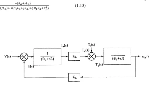
The relationships are represented in block-diagram form as figure (1.2). The transfer functions ω𝑚(𝑠)
𝑉(𝑠) and ω𝑚(𝑠)
𝑇𝐼(𝑠) which are derived from the block-diagram are given by.
𝐺ωV(𝑠) =ω𝑚(𝑠) 𝑉(𝑠) = 𝐾𝑏 𝑠2(𝐽𝐿𝑎)+ 𝑠(𝐵1𝐿𝑎+𝐽𝑅𝑎)+( 𝐵1𝑅𝑎+𝐾 𝑏2) (1.12) 𝐺ωI(𝑠) =ω𝑚(𝑠) 𝑇𝐼(𝑠) =
ADAPTIVE CRUISE CONTROL SYSTEM AND ITS IMPLEMENTATION 5 −(𝑅𝑎+𝑠𝐿𝑎) 𝑠2(𝐽𝐿 𝑎)+ 𝑠(𝐵1𝐿𝑎+𝐽𝑅𝑎)+( 𝐵1𝑅𝑎+𝐾𝑏2) (1.13)
Figure 1.2 Block diagram of the DC motor. 2. DESIGN OF PID CONTROLLER
2.1 CONTROL ACTION
The relationship between the output of the controller u (t) and the actuating error signal e (t) in a controller which possesses proportional control action is
𝑢(𝑡) = 𝐾𝑝 𝑒(𝑡)
In case of Laplace-transformed quantities, it is defined as
𝑉(𝑠)/𝐸(𝑠) = 𝐾𝑝 (2.1)
where Kp denotes the proportional gain[5].
The value of the controller output u (t) in a controller with integral control
action, increases or decreases in proportion to the actuating error signal e (t):
𝑑𝑢(𝑡)
𝑑𝑡 = 𝐾𝑖. 𝑒(𝑡)
𝑢(𝑡) = 𝐾𝑖 ∫ 𝑒(𝑡)𝑑𝑡0𝑡
where Ki is an integral constant defined by the designer of the control system[5]. The transfer function of the integral controller is
M. SARP, A. TOPÇU AND H. A. ILGIN 6 𝑼(𝒔) 𝑬(𝒔)
=
𝑲𝒊 𝒔 (2.2)The control action of a proportional-plus-integral controller is defined by
𝑢(𝑡) = 𝐾𝑝. 𝑒(𝑡) +𝐾𝑝
𝑇𝑖∫ 𝑒(𝑡)𝑑𝑡 𝑡
0 or the transfer function of the controller is
𝑈(𝑠)
𝐸(𝑠)= 𝐾𝑝 (1 + 1
𝑇𝑖𝑠) (2.3)
where Ti is called the integral time[5].
The control action of a proportional-plus-derivative controller is defined by 𝑢(𝑡) = 𝐾𝑝. 𝑒(𝑡) + 𝐾𝑝. 𝑇𝑑.𝑑𝑢(𝑡)
𝑑𝑡 and the transfer function is
𝑈(𝑠)
𝐸(𝑠)= 𝐾𝑝(1 + 𝑇𝑑. 𝑠) (2.4)
where Td is called the derivative time[5].
The combination of proportional control action, integral control action, and derivative control action constitutes proportional-plus-integral-plus-derivative
control action, and it exhibits the characteristics of each control actions [5]. The
equation of this control action is given by
𝑢(𝑡) = 𝐾𝑝. 𝑒(𝑡) +𝐾𝑝 𝑇𝑖∫ 𝑒(𝑡)𝑑𝑡 𝑡 0 + 𝐾𝑝. 𝑇𝑑.𝑑𝑢(𝑡) 𝑑𝑡 or the transfer function is
𝑈(𝑠)
𝐸(𝑠)= 𝐾𝑝 (1 + 1
𝑇𝑖𝑠+ 𝑇𝑑. 𝑠) (2.5)
where Kp is the proportional gain, Ti is the integral time, and Td is the derivative
time.
ADAPTIVE CRUISE CONTROL SYSTEM AND ITS IMPLEMENTATION 7 The proportional control of a plant which does not have an integral controller exhibits a steady state error, or offset, in the unit step response. The integral control action is included in the controller in order to eliminate such an offset, or error [5].
In the integral control action, the control signal which is the output signal of the controller at any instant is the area under the actuating-error-signal curve up to that instant [5]. The control signal u (t) can have a nonzero value even if the actuating error signal e (t) is zero, as shown in Figure 2.1(a). However, this is not possible in the proportional control action because a nonzero control signal means a nonzero actuating error signal which indicates that there is an offset in response to the step input [5]. Integral control action, while eliminating offset or steady-state error, may cause to oscillatory response of slowly decreasing amplitude or even increasing amplitude, both of which are usually undesirable[5].
(a) (b)
Figure 2.1
(a) Plots of e (t) and u (t) curves showing nonzero control signal when the actuating error signal is zero (integral control); (b) plots of e (t) and u (t) curves showing zero control signal when the actuating error signal is zero (proportional control).
2.3 PROPORTIONAL CONTROL OF SYSTEMS
In the case of a proportional control action which doesn’t possess an integrator, there is a steady-state error in the unit step response. This error can be eliminated only if integral control action is included in the controller [5].
M. SARP, A. TOPÇU AND H. A. ILGIN 8
Figure 2.2 proportional control systems.
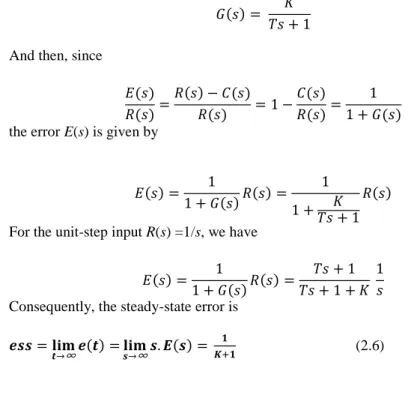
If we consider the system shown in Figure 2.2, the steady-state error in the unit-step response of the system is obtained by firstly defining
𝐺(𝑠) = 𝐾
𝑇𝑠 + 1 And then, since
𝐸(𝑠) 𝑅(𝑠)= 𝑅(𝑠) − 𝐶(𝑠) 𝑅(𝑠) = 1 − 𝐶(𝑠) 𝑅(𝑠)= 1 1 + 𝐺(𝑠) the error E(s) is given by
𝐸(𝑠) = 1
1 + 𝐺(𝑠)𝑅(𝑠) = 1 1 +𝑇𝑠 + 1𝐾
𝑅(𝑠) For the unit-step input R(s) =1/s, we have
𝐸(𝑠) = 1 1 + 𝐺(𝑠)𝑅(𝑠) = 𝑇𝑠 + 1 𝑇𝑠 + 1 + 𝐾 1 𝑠 Consequently, the steady-state error is
𝒆𝒔𝒔 = 𝐥𝐢𝐦
𝒕→∞𝒆(𝒕) = 𝐥𝐢𝐦𝒔→∞𝒔. 𝑬(𝒔) = 𝟏
𝑲+𝟏 (2.6)
2.4 INTEGRAL CONTROL OF SYSTEMS
Figure 2.3 shows general block-diagram of integral control systems. The closed-loop transfer function of the system is
𝐶(𝑠) 𝑅(𝑠)=
𝐾 𝑠(𝑇𝑠 + 1) + 𝐾
ADAPTIVE CRUISE CONTROL SYSTEM AND ITS IMPLEMENTATION 9
Figure 2.3 Integral control systems.
Hence 𝐸(𝑠) 𝑅(𝑠)= 𝑅(𝑠) − 𝐶(𝑠) 𝑅(𝑠) = 𝑠(𝑇𝑠 + 1) 𝑠(𝑇𝑠 + 1) + 𝐾
Because the system is stable, the steady-state error in response to unit step input can be calculated from the final-value theorem:
𝑒𝑠𝑠 = lim 𝑡→∞𝑒(𝑡) = lim𝑠→∞𝑠. 𝐸(𝑠) = 𝑠. 𝑠(𝑇𝑠+1) 𝑠(𝑇𝑠+1)+𝐾 1 𝑠= 0 (2.7)
The result of the equation (2.7) shows that the steady-state error is zero for the systems with integral controller, while the control systems with proportional controller give an offset. This is an important advantage of integral controller. [5]. 2.5 RESPONSE TO TORQUE DISTURBANCES (PROPORTIONAL-PLUS-INTEGRAL CONTROL)
A proportional-plus integral controller can be used instead of the proportional controller in order to eliminate offset due to torque disturbance. In systems with integral controller, a torque is developed by the controller as long as there is an error signal. This torque reduces the error signal and provides a stable control system [5].
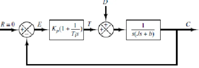
Block-diagram of the proportional-plus-integral control of the load element which consists of moment of inertia and viscous friction is basically shown in Figure 2.5.
Figure 2.4 Proportional-plus-integral control of a load element consisting of moment of inertia and viscous friction.
M. SARP, A. TOPÇU AND H. A. ILGIN 10
The closed-loop transfer function between C(s) and D(s) is
𝐶(𝑠) 𝐷(𝑠)= 𝑠 𝐽𝑠3+𝑏𝑠2+𝑘𝑝.𝑠+𝐾𝑝 𝑇𝑖 (2.8)
When the reference input, r (t) =0, the error signal is calculated from
𝐸(𝑠) = − 𝑠
𝐽𝑠3+ 𝑏𝑠2+ 𝑘𝑝. 𝑠 +𝐾𝑝 𝑇𝑖
𝐷(𝑠)
If the roots of the characteristic equation have negative real parts, which means the system is stable,
𝑞(𝑠) = 𝐽𝑠3+ 𝑏𝑠2+ 𝑘𝑝. 𝑠 +𝐾𝑝 𝑇𝑖
then the steady-state error in the response to a unit-step disturbance torque can be calculated from the final-value theorem as follows[5]:
𝑒𝑠𝑠 = lim 𝑡→∞𝑒(𝑡) = lim𝑠→∞𝑠. 𝐸(𝑠) = 𝑠. −𝑠 𝐽𝑠3+𝑏𝑠2+𝑘𝑝.𝑠+𝐾𝑝𝑇𝑖 1 𝑠= 0 (2.9)
Thus the integral control action eliminates steady-state error to the step disturbance torque while the proportional control action increases stability of the system. [5]. 2.6 DERIVATIVE CONTROL ACTION
Derivative controller can be added to the proportional controller in order to increase the sensitivity of the controller. [5] Derivative control action can respond to the rate of change of the actuating error so quickly that it can initiate an early corrective action before the magnitude of the actuating error becomes too large.
Derivative control does not affect the steady-state error directly, but it adds damping to the system so that a larger value of the K can be used in the system, which increases the steady-state accuracy [5].
Unlike integral controller and proportional controller, derivative control operates on the rate of change of the actuating error and not the actuating error itself. For this reason, it always needs to be used in combination with proportional or proportional-plus-integral control action [5].
ADAPTIVE CRUISE CONTROL SYSTEM AND ITS IMPLEMENTATION 11
3. DESIGN OF ADAPTIVE CRUISE CONTROL SYSTEM AND SIMULATION RESULTS
Specifications of the DC motor used in the proposed ACC vehicle following system are:
Terminal resistance R=2.5 Ohm, Terminal inductance L=227e-6 Henry, Torque constant Kt =13.8e-3
,
EMF constant Ke = 13.8e-3,
Rotor inertia J = 1.36e-6 kg-m2,
Viscous damping Coefficient B=5.8e-6 kg-m2/sn.
Figure 3.1 Block diagram of the DC motor used in the ACC system. By using these specifications obtained from data sheet of the DC motor , transfer function of the DC motor is achieved as follow,
𝐺(𝑠) = 4.47𝑥10
7
𝑠2+ 1.102𝑥104𝑠 + 6.638𝑥105
when observed the roots of the characteristic equation , it can be easily seen that the reel parts of the roots are negative, which indicates that the motor is stable on open-loop operation. Figure 3.1 shows block diagram of DC motor in Simulink.
M. SARP, A. TOPÇU AND H. A. ILGIN 12
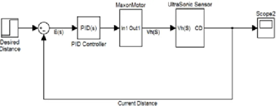
Figure 3.2 shows the general block diagram of the ACC vehicle following system designed in Simulink. The effects of the integral and derivative control actions on the system are analyzed by applying unit step signal to the desired distance input in Figure 3.2.
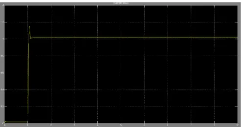
Figure 3.3 The effect of the proportional control action on the system performance. The output of the system is seen in figure 3.3 when PID controller is reduced to P controller by setting the proportional gain, Kp to 50 and both integral gain, Ki and
derivative gain, Kd to zero. After reaching %16 maximum percent overshoot, the
output response of the system becomes steady state. However, steady state error can be easily seen in Figure 3.4.
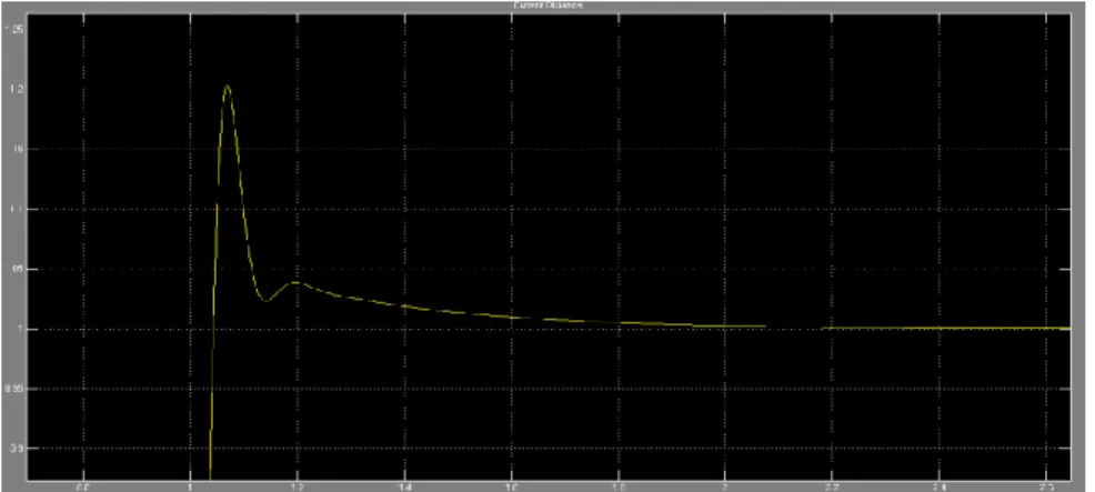
ADAPTIVE CRUISE CONTROL SYSTEM AND ITS IMPLEMENTATION 13 As observed in figure 3.5, an increase in proportional gain, Kp increases the
maximum percent overshoot value, which cause an oscillation in the output of the system by decreasing the damping ratio. If Kp increases much more, the output of
the system becomes as illustrated in Figure 3.5, which also indicates an increase in oscillation by decreasing the damping ratio.
Figure 3.5 The effect of increased proportional controller (KP) on the system performance.
Steady state error can be reduced by increasing Kp, but it never becomes
zero. Only if integral controller is added to system, steady state error becomes zero. Figure 3.6 shows the effect of PI controller on the system whose integral gain, Ki
equals to 150 and proportional gain Kp equals to 50. As illustrated in Figure 3.6,
adding integral controller to the system makes steady state error zero.
M. SARP, A. TOPÇU AND H. A. ILGIN 14
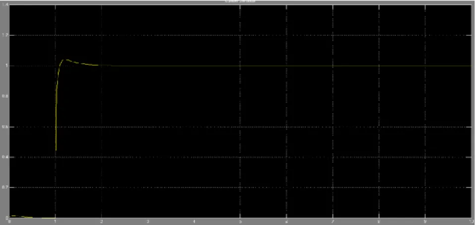
When derivative controller whose derivative gain equals to 1.5 is added to system without changing Kp and Ki in order to form PID controller, the output of the
system becomes as illustrated in Figure 3.7. Derivate controller decreases oscillation in the output of the system by increasing the damping ratio without effecting steady state error. As seen in figure 3.7, it also decreases the maximum percent overshoot value. Moreover, it helps the system perform on high gain operation decreasing the maximum percent overshoot value. When Kp equals to 50 and Ki equals to 600,
which indicates an increase in total gain, it can be easily seen in figure 3.8 that system operates without surpassing the permissible maximum percent overshoot value.
Figure 3.7 The effect of PID controller on the system.
Because derivative control action helps integral gain increase, it helps settling time decrease. As a result, desired output response is obtained when Kp
equals to 50, Ki equals to 600, and Kd equals to 1.5.
ADAPTIVE CRUISE CONTROL SYSTEM AND ITS IMPLEMENTATION 15
CONCLUSION
In this paper, the effects of PID on the ACC vehicle following system are investigated in detail and the response of the system is illustrated in Simulink to demonstrate how PID parameters affect the system in separately. While tuning PID controller, it is important to note that transient response specifications, such as maximum percent overshoot value, settling time, rise time, must be determined carefully because transient response has a direct effect on the rate of acceleration and deceleration of the vehicle, which cause big problems in real life. Driving can be safer and more efficient by exploiting the proposed ACC.
REFERENCES
[1] P. Ioannou and C. Chien, Autonomous intelligent cruise control, IEEE transaction on vehicular technology, vol. 42, pp. 657-672, November 1993. [2] A. Vahidi and A. Eskandarian, Research advances in intelligent collision avoidance and adaptive cruise control, IEEE transaction on intelligent transport systems, vol. 4, No. 3, pp. 143-153, September 2003.
[3] R.Krishan, Electronic, Motor drives, modeling, analysis and control, 2001. [4] Electro-Craft Corporation. DC Motors, speed controls, servo Systems. Pergamon Press, 1977
[5] K. Ogata, Modern control engineering(Fifth Edition), Prentice Hall, 2010. [6] K. Ogata, Discrete-time control system, Prentice Hall, 1995.
[7] K. J. Astrom & T. Hagglund, PID Controllers: Theory, design and tuning, International Society for Measurement and Con, 1995.
[8] Paul C. Krause, Oleg Wasynczuk and Scott D. Sudhoff, Analysis of electric machinery and drive systems(Second Edition), Willey-Interscience, 2002. [9] John D. Jackson. Classical electrodynamics (Second Edition), John Wiley & Sons, New York, 1975.