Full Terms & Conditions of access and use can be found at
http://www.tandfonline.com/action/journalInformation?journalCode=twrm20
Waves in Random and Complex Media
ISSN: 1745-5030 (Print) 1745-5049 (Online) Journal homepage: http://www.tandfonline.com/loi/twrm20
Conversion from constitutive parameters to
dispersive transmission line parameters for
multi-band metamaterials
Yusuf Ozturk, Asim Egemen Yilmaz & Ekmel Ozbay
To cite this article: Yusuf Ozturk, Asim Egemen Yilmaz & Ekmel Ozbay (2016) Conversion from constitutive parameters to dispersive transmission line parameters for multi-band metamaterials, Waves in Random and Complex Media, 26:2, 211-223, DOI: 10.1080/17455030.2015.1134851 To link to this article: https://doi.org/10.1080/17455030.2015.1134851
Published online: 18 Jan 2016.
Submit your article to this journal
Article views: 119
View related articles
http://dx.doi.org/10.1080/17455030.2015.1134851
Conversion from constitutive parameters to dispersive
transmission line parameters for multi-band metamaterials
Yusuf Ozturka,b , Asim Egemen Yilmaza and Ekmel Ozbayc
aelectrical and electronics engineering department, ankara University, ankara, Turkey; bThe scientific and Technological Research Council of Turkey (TÜBİTaK) - UlaKBİm, ankara, Turkey; cnanotechnology Research Center, Bilkent University, ankara, Turkey
1. Introduction
Metamaterials could be classified as a core technology for lots of novel implementations including phase shifters/compensators [1], resonators [2], antennas [3], absorbers [4], mem-ory [5] etc. The first experimental samples (the split-ring resonator (SRR)-based metamateri-als) [6] were realized three decades later then the definition of the metamaterial theory.[7] Up to now, a variety of different-type metamaterials have been presented based on their geometrical or material selections, excitation-directions, etc. After designing a new type metamaterial, the dependence of the magnetic resonance frequency on the geometrical parameters of the metamaterial could be studied for tunable applications.[8] It is shown that the composite structure may be regarded as a uniaxial indefinite material loaded with impedance sheets, and that the negative refraction effect may be characterized using homogenization methods.[9]
ABSTRACT
In this study, we explain an approach including conversion from constitutive parameters to dispersive transmission line parameters using the double-band DNG (double-negative) properties of the circular type fishnet metamaterials. After designing the metamaterial structure, the numerical calculations and the composite right/left-handed (CRLH) modeling of circular-type metamaterials are realized in free space. Detailed dispersion characteristics give us the opportunity to explain the true behavior of the inclusions during the analysis stage. By combining the results coming from the standard retrieval procedure with the conventional CRLH theory, we calculate the actual values of the transmission line parameters for all frequency regimes. The constitutive parameters of an equivalent CRLH transmission line are derived and shown to be negative values. It is shown that the constitutive parameters present the same behavior for all negative refractive index regimes. The double-negative properties and the phase advance/lag behavior of metamaterials are observed based on the dispersive transmission line parameters.
© 2016 Taylor & Francis
ARTICLE HISTORY Received 27 august 2015 accepted 16 december 2015
One of the popular metamaterial application areas is electrically small antennas (ESAs) with metamaterials. As well known, ESAs with size considerably smaller than usual half-wave-length antennas are more suitable for applications in the growing era of wireless and mobile communication technologies. Some application examples for this purpose are metamateri-al-based efficient ESAs,[10] electrically small split-ring resonator antennas,[11] and electrically small patch antenna loaded with metamaterial.[12] For practical implementations, some-times, additional matching networks like capacitive loading to match the input impedance are necessary. Firstly, the circular-type metamaterials were designed to operate in optical regime.[13] Planar fishnet-type metamaterials gained popularity due to their polarization-in-dependent localization and some advantages of their fabrication process. A suitable example of these structures was also designed for microwave regime.[14]
In this paper, we introduce a new general method to analyze dispersive properties of metamaterials by combining the current retrieval procedures with the composite right/left-handed (CRLH) theory. In this approach, it is not necessary to use the direct line impedance value of the device, the sign function for the dispersion relation or operational bandwidth limitations to extract the transmission line parameters. We use circular-type fishnet meta-materials (CF-MM) structure for our analysis because we confirmed its negative refractive index behavior in our previous study theoretically and experimentally.[15] Here, we show dual-band DNG properties of these inclusions. Additionally, the dispersion characteristics of the fabricated inclusions are identified in this paper to clarify the backward wave propa-gation. The equivalence circuit modeling or the transmission line modeling (TLM) of meta-materials is used to analyze and design metameta-materials. However, instead of an LC network implementation of TLM,[16,17] we will explain dispersive behavior of the TL parameters to demonstrate the complicated physical mechanism of LHM region, which is different from the conventional LC filter examples. The TLM parameters handled by this technique demonstrate the difference between the classical LC network representation and the actual behavior of dispersive metamaterials.
This paper is organized as follows: Section 2 contains the metamaterial structure defi-nition. Section 3 presents the CRLH modeling of the CF-MMs based on the transmission spectra, the standard retrieval procedure, and the dispersion characteristics. In Section 4, the dispersive transmission line parameters are calculated using our modified CRLH modeling approach and conclusions are placed in Section 5.
2. Structure definition
The circular fishnet metamaterial (CF-MM) operating independent of the incident polariza-tion was designed, fabricated, and measured in order to characterize its behavior completely in our previous paper.[15] Polarization independency of the structure is due to its symmetric configuration. A schematic view of CF-MM unit cell is depicted in Figure 1(a). The structure consists of the low-loss Teflon substrate (𝜀r = 2.19 and tangent loss of δ = 0.005) with a trans-parent view and the highlighted metal parts (copper) as PEC layer. As reported before, the lower tangent loss value is vital to achieve left-handed resonance behavior. The thicknesses of the Teflon layer and the copper layer are 1 mm and 20 micrometer, respectively. The unit cell has the complementary parameters wherein choosing the dimensions as ax = ay = a = 14 mm and the radius r = 0.25a results in a fully circular and polarization-independent inclusions. For multilayer deployment of CF-MMs, the distance between stacked layers equals to az = 2 mm.
During CRLH-TL modeling, the distance value must be small enough to achieve the lumped element representation of the inclusions (Δz = az = 𝜆∕11.5 ∼ 𝜆∕7.5) as depicted in Figure
1(b). The incident EM wave propagates along the z-direction perpendicular to the E-field parallel to the y-axis and the H-field parallel to the x-axis. Figure 2 shows the measured and calculated S parameters of the CF-MM.
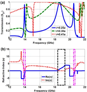
During numerical calculations, the operating frequency regime is extended to 12–22 GHz to represent the dispersion change according to the structural parameters. The transmission spectra of the unit cell for three different radius aperture (r = 0.25a, r = 0.30a, and r = 0.41a)
Figure 1. (a) schematic representation of the CF-mm structure. (b) The basic representation of an ideal CRlH transmission line.
Figure 2. Calculated transmission (the blue solid line), measured transmission (the red-dashed), calculated phase (the black-dashed), and measured phase (the green dash-dot line) spectra for r = 0.25a. The inline graphics corresponds to the 1-layer fabricated sample consisting of 10 × 10 unit cells.
are calculated using a commercial electromagnetic full-wave software and the results are presented in Figure 3(a). On the other hand, the standard retrieval procedure [18] is imple-mented after the CF-MM structures are simulated. For this purpose, a unit cell is employed along z-direction and the effective permittivity and permeability values are then derived from the transmission/reflection coefficients (S21 and S11) and phase values of a unit cell of CF-MM. For a plane wave incident normally on a homogeneous slab of thickness d = az = 2 mm with the origin coinciding with the first face of the slab, S11 is equal to the reflection coefficient, and S21 is related to the transmission coefficient. After the S parameters are related to refrac-tive index n and impedance z, the refracrefrac-tive index n and the impedance z are obtained by inverting the equations accordingly. The condition for the passive medium requirements leads to | |n ′ z′′| |≤n ′′
z′. The calculated refractive index values n are given by Figure 3(b) for r= 0.25a. As shown in this figure, the double-negative (DNG) region is observed in the two different frequency bands at 13.75–14.1 GHz and 20.5–20.7 GHz. The double-positive (DPS) spectrum is centered nearly at 18.5 GHz and represented as a relatively wider bandwidth according to the DNG region. However, there is another factor affecting electromagnetic wave propagation in +z or –z direction, the imaginary parts of the refractive index. It is clear to identify that imaginary parts go to zero-value for the resonance frequencies of the LHM and RHM regions. By noting the dual-band LHM behavior, the calculated refractive index values will also be used to create the dispersion characteristics of the inclusions.
Figure 3. (a) Calculated transmission spectra for the three different aperture radius (the blue solid line for r = 0.25a, the green-dashed line for r = 0.30a, and the red dotted line for r = 0.41a). (b) The refractive
index values calculated using the retrieval procedure for r = 0.25a. There, the pink rectangular boxes
3. Experimental results
The experiments are performed in free space and at room temperature using two standard gain horn antennas. The distance between the antennas was kept fixed at 30 cm away and the sample was located at the central position. Firstly, a TRL calibration procedure was imple-mented on the network analyzer to eliminate environmental noises. After the free-space calibration, the transmission spectra and phase spectra have been measured in the same position. The measured and calculated transmission (S21) and phase (θT) characteristics of the CF-MM medium are displayed in Figure 2. The experimental data show a compatibility with the outputs of the measurements.
In fact, the resonant-mode behavior is observable centered at 13.8, 18.5, and 20.4 GHz, respectively. The highest resonance, however, were not measured according to experimen-tal results. This anomaly will be explained using dispersion analysis and transmission line parameters.
4. CRLH modeling of CF-MMs
A schematic of an electronic circuit including the symbols of resistors, capacitors, inductors, diodes, and the like aims to represent the function of the device rather than its shape or size. On the other hand, any TEM-type transmission line including the two-wire line, coaxial line, parallel-plate line, strip or micro-strip line has similar functionalities different from the higher order transmission lines. Due to simplicity, a general transmission is mainly depicted in the two-wire line by subdividing it into differential sections each of length Δz in the propagation direction. This representation called the lumped-element circuit consists of four basic ele-ments (the transmission line parameters): the combined resistance (R′ in Ω/m), inductance (L′ in H/m), conductance (G′ in S/m), and capacitance (R′ in F/m) of both conductors per unit length. As mentioned later, the resistance and conductance values are not used in the lossless TL modeling.
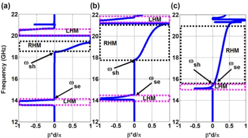
During our TLM process, we use CRLH modeling approach as a basic theoretical frame-work.[19–23] As mentioned this study, the general TL approach provides insight into the physical phenomena of LHMs and provides an efficient design tool for LH applications. LHMs are considered to be a more general model of CRLH structures, which also include right-handed (RH) effects that occur naturally in practical LHMs. Some details of the purely right-handed (PRH) and purely left-handed (PLH) homogenous models were presented in these reference papers. On the other hand, we show the CRLH modeling of CFMMs by modifying the current theory and the characterization process. As depicted in Figure 1(b), a CRLH model consists of the combination of a PRH (a per-unit length series inductance L′R and a per-unit length shunt capacitance CR′) and PLH (a times-unit length series capacitance CL′ and a times-unit length shunt inductance L′L) model. For simplicity, we assume CFMMs as an ideal transmission line due to the low-loss tangent value of the dielectric layer and the PEC behavior of metallic parts of the structure. In this situation, the propagation constant of the TL is expressed as γ = jβ (instead of the general form: γ = α + jβ). This means that the phase constant β is purely real for the pass-band frequency range, while it is purely imag-inary in the stop-band frequency range. If the phase response of a medium is dependent on the frequency, the medium is called dispersive. The phase constant is calculated directly from the refractive index values n using β = (nω)/c0, where ω and c0 denote the frequency
and the speed of light, respectively (The results are presented in Figure 4). Based on PLH TL (the per-unit length impedance Z′ and per-unit length admittance Y′), the phase velocity vp= 𝜔∕𝛽 = −𝜔2(L�LCL�)1∕2<0 and the group velocity have opposite signs as expected for LHM conditions as vg= (𝜕𝛽∕𝜕𝜔)−1= +𝜔2(L�
LC � L)
1∕2>0.
where s(𝜔) is the sign function based on the LH and RH ranges. 𝜔′L and 𝜔′R are introduced as the left and right resonance variables, while κ = L�
RC � L+ L � LC � R
A transmission line is characterized by its two fundamental properties: the propagation constant (γ) and characteristics impedance (Z0). One of the advantages of our approach, we do not need to use any impedance information belonging to the TL. In fact, there is a dilemma resulted in the lossless modeling. As shown in Figure 4(a), there is some attenuation along the semi-stop-band region between 14.2 and 18.4 GHz for r = 0.25a. However, it is easy to avoid this problem by increasing the radius of the aperture in our structure. By selecting r= 0.30a as depicted in Figure 4(b), for example, not only the more decreased stop-band (between 14.6 and 17.6 GHz) is obtained, but also the attenuation factor is partially disappeared as desired. Unfortunately, the second LHM band is affected in a negative manner for every increment in the radius aperture. Additionally, we will completely explain the characteristic (1) Z�= j ( 𝜔L�R− 1 𝜔C� L ) (2) Y�= j ( 𝜔CR�− 1 𝜔L� L ) (3) 𝛾 = 𝛼 + j𝛽 = √Z�Y� = js(𝜔) � � 𝜔 𝜔�R �2 + �𝜔� L 𝜔 �2 − 𝜔�L2
Figure 4. Calculated dispersion graphics of the CFmms for r = 0.25a (a), r = 0.30a (b), and r = 0.41a (c).
dispersion diagrams for metamaterials as a general case with lower/upper stop-band, atten-uation, unstable, LHM, and RHM regions. The opposite phase velocities for the LHM and RHM regions are verified on the dispersion graphics. One should take into account the operation region for each case, for example, 15–21 GHz for r = 0.41a. As a marginal limitation, it is nearly achievable to realize a completely balanced line with r = 0.41a selection. In this situation, the inclusion satisfies the condition of (L�RCL�= L�LCL�) and has smaller phase constant values. 5. Dispersive TL parameters
After experimental verification of negative refractive index, enhancements in electrical per-mittivity and magnetic permeability values have gained popularity due to requirements for practical microwave applications such as resistive sheets and near-to-zero epsilon materials. Currently, the actual capacitance and inductance values of inclusions give us a deep under-standing for material behavior. As a result, one could change the geometrical shape of the structures based on the real values of the transmission line. Up to now, we reviewed the CRLH theory and implemented it for CF-MMs to reveal dispersion graphics. In this part of paper, we calculate the TL parameters with frequency dependency rather than a fixed wavelength or a group of wavelengths. For this purpose, we modify and simplify the current method to complete the calculation of the constitutive TL parameters. At this point, we know the relationship between the resonance frequencies and the TL parameters as:
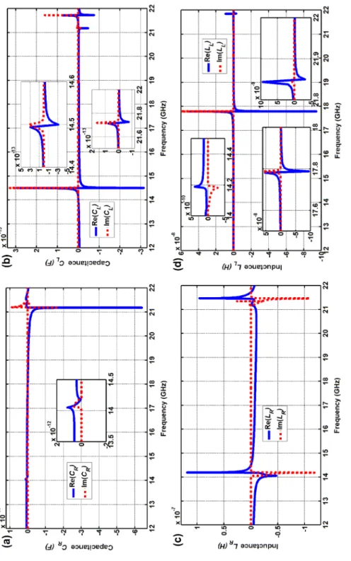
According to Equations (4)–(7), we have the four unknown constitutive parameters in four interrelated equations. To solve these equations, some additional information is necessary as suggested using the line impedance values and the cut-off frequencies. At this stage, we simplify the process by inserting the serial and shunt resonance values from any electrody-namics simulation software based on the dispersion results. In this case, we select the serial and shunt resonance frequencies as ωse = 14.20 GHz and ωsh = 18.45 GHz for r = 0.25a and ωse = 14.50 GHz and ωsh = 17.75 GHz for r = 0.30a, respectively. Using this prior information gathered from the external simulation tool, we rearrange Equations (8) and (9) based on the known resonance values from our dispersion analysis in addition to the relative permittivity and permeability values from the standard retrieval procedure as Equations (10) and (11).
(4) 𝜔�R= 1∕ √ L�RCR�(rad.m)/s (5) 𝜔�L= 1∕ √ L�LCL�(rad.m)/s (6) 𝜔se= 1∕ √ L�RCL�rad/s (7) 𝜔sh= 1∕ √ L�LCR�rad/s
Figur
e 5.
Calcula
ted the ideal tr
ansmission line par
amet ers f or r= 0.25 a .
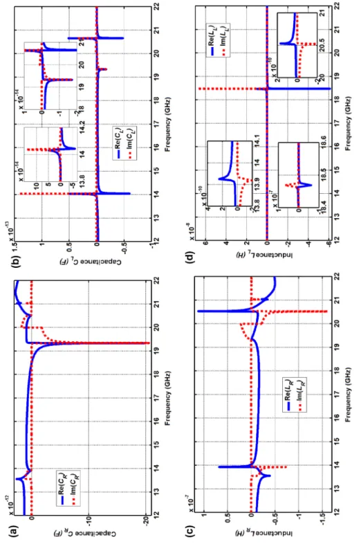
Rigorously, one could determine the serial and shunt resonance frequencies directly by selecting proper points on the transmission spectra satisfying the condition 20 log[S21(wsh,se)]= −3 dB. In this study, we choose to use the refractive index values containing imaginary parts coming from the standard retrieval algorithm. The results are depicted in Figure 5 for r = 0.25a and in Figure 6 for r = 0.30a. The RH CR′ and L′R parameters are strongly dependent on the electrical permittivity and permeability values as expected. In contrast to this situation, the LH CL′ and L′L parameters are only observed in the resonance points. C′
L takes nearly −2 fF (femto-Farads) and L ′
L equals to 5 nH with a non-dispersive
behavior except from resonance frequencies. In addition to the real values, we extracted the imaginary parts to point out the exact behavior of CF-MMs at resonance frequencies.
As shown in Figure 5, for the DNG media (centered at 13.8 and 20.6 GHz): (i) CR has positive real and imaginary parts, especially imaginary parts show a gain mechanism for the LHM resonance. (ii) LR has a positive real and a negative imaginary part where the positive real peaks identify LHM boundaries where negative imaginary parts behave as a gain. (iii) In the LHM bands, CL has very small positive imaginary values as a gain mechanism and the real part is changing from negative to positive values. An asymptotic real part (from positive to negative) and a positive imaginary peak take place at the end of LHM band to realize a transition from backward-wave propagation to the attenuation region. (iv) LL has positive real parts and negative imaginary parts, imaginary parts represent a gain mechanism starting from 13.5 GHz for the first LHM band.
For the DPS medium (centered at 18.7 GHz): (i) CR has negative real and zero-imaginary parts, a negative imaginary peak at the end of the RHM band. At the point of 18.4 GHz, its sign switches from negative to positive as a transition expected in the dispersion graphics.(ii) LR has negative real and near-to-zero imaginary parts following the positive imaginary part presents a loss mechanism. (iii) CL has a negative real peak followed by a negative imaginary part. (iv) LL equals to zero and has negative real and positive imaginary peaks at 18.4 GHz (see the inline graphic), the imaginary parts represent a transition mechanism.
(8) 𝜇= 𝜇(𝜔) = L�R− 1 𝜔2CL� (9) 𝜀= 𝜀(𝜔) = CR�− 1 𝜔2L�L (10) 𝜇= 𝜇(𝜔) = 𝜇r(𝜔) ∗ 𝜇0= ( 𝜔 𝜔se )2 − 1 𝜔2CL� (11) 𝜀= 𝜀(𝜔) = 𝜀r(𝜔) ∗ 𝜀0= ( 𝜔 𝜔sh )2 − 1 𝜔2L�L
Figur
e 6.
Calcula
ted the ideal tr
ansmission line par
amet ers f or r= 0.30 a .
Under the conditions that the radius aperture of the CF-MMs is changed from r = 0.25a to r = 0.30a, we extract similar characteristics for TL parameters as depicted in Figure 6. Due to very similar behavior, it is not necessary to explain the change of the TL parameters. However, one should notice the weakness occurred in resonance frequencies as expected in dispersion graphics. In this paper, we do not investigate the physical rationale of the TL parameters, for example, the meaning of negative inductance and capacitance. Time-domain analysis of this kind of structure can be studied in future to investigate causality principle. Here, we simply introduce a method to characterize the dispersive transmission line parameters and evaluate the actual resonance behavior. Specifically, these results may be beneficial to design of structures similar to ESAs given in the introduction part. Lastly, the simulation and calculations have been realized for a number of different aperture radii in logical form of parameter sweep. Due to space limitations and paper organization, there are only necessary and enough information explaining our approach.
6. Circuit theory verification
The proposed approach is verified by standard circuit analysis according to equivalent circuit model in Figure 1(b) and Equations (12) and (13), which is completely independent from the simulation and CRLH modeling process. To characterize the CF-MM structure, the equivalent circuit model with element values represented in Figure 5 is established for = 0.25a. Figure
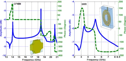
7(a) shows the corresponding LHM (13.8 and 20.5 GHz) and RHM (18.5 GHz) resonances. Moreover, the phase advance for LHM regime and phase lag for RHM regime, one of the metamaterial characteristics, is also observable in which the proposed method differs from conventional filter models. The sharpness of the phase transitions and weakness of reso-nance values (−6.2, −4.7, −6.5 dB) are classified as errors based on the ideal CRLH modeling instead of the efficient one.
Lastly, the proposed method is implemented on the SRR-type metamaterial offered in [8] to investigate validity of the approach for different-type metamaterials especially co-planar types. It consists of two rings (0.9 mm) separated by a gap (0.2 mm) on a FR-4 circuit board. A single copper SRR unit is constructed with design parameters of inner radius (2.5 mm) and outer radius (3.6 mm). The SRR medium displays an LHM band (centered at 2.8 GHz) and an RHM band (centered at 5.2 GHz) throughout the interested frequency range. The calculated TL parameters have similar characteristics to CF-MMs to reach the expected resonance values and the phase advance/lag behavior as depicted in Figure 7(b).
The measured dispersion curve is seen to be very close to the full-wave calculations as depicted in Figure 2. To explain the differences between Figures 2 and 7(a), we focus on the standard retrieval procedure and the lossless CRLH modeling. Using the retrieval analysis (12) V0− Vg 1 j𝜔C� L + j𝜔L�R + V0 1/ j𝜔CR� + V0 j𝜔L� L = 0 (13) H(j𝜔) = V0 Vg = 𝜔2L�LCL� 𝜔2L�RCL�+ 𝜔2L�RCR� + 𝜔2L�LCL�− 𝜔4L�LL�RCL�CR� − 1
and the effective medium theory, the unit cell is defined as a perfectly homogenous material. In fact, this solution includes spatial dispersion effects especially occurring at resonance frequencies. Improved homogeneity and isotropy can overcome these problems to some extent. In particular, the SRR-type composite unit cell has much broader bandwidth in LHM and RHM regimes and therefore leads a smooth slope in the phase graphics. Secondly, instead of the ideal (lossless) CRLH modeling, an attenuation factor should be added to the modeling process to represent losses faced with. At this point, the structures designed with low insertion losses, for example, interdigital capacitors, may be beneficial to analyze non-resonant-type metamaterials.
7. Conclusions
In conclusion, we have analyzed double-band DNG properties of CF-MMs and provided an approach to exactly calculate the TL parameters. Additionally, we explain the resonance behavior of both LHM and RHM bands. Based on the dispersion results, we focus on the transition bands and their relation with TL parameters. At the end of this study, the difference could be summarized as the change points of the current CRLH process and our approach. Instead of using the values belonging to the cut-off frequency and line-impedance hidden in the electromagnetic medium parameters, the shunt and serial resonance frequencies are inserted as additional information to solve the transmission line parameters. By implement-ing this modification, we reach the dispersive transmission line parameters (inductance and capacitance values) with a whole dispersive nature. All process can be categorized in the four stages: (i) simulation of the structure, (ii) retrieval analysis and dispersion engineering, (iii) CRLH modeling, (iv) calculation of the TL parameters. Good agreements between simu-lations, calcusimu-lations, and circuit theory verification confirm the efficiency of our approach. Disclosure statement
No potential conflict of interest was reported by the authors.
ORCID
Yusuf Ozturk http://orcid.org/0000-0003-2762-5265
References
[1] Antoniades MA, Eleftheriades Gv. Compact linear lead/lag metamaterial phase shifters for broadband applications. IEEE Antennas Wirel. Propag. Lett. 2003;2:103–106.
[2] Engheta N. An idea for thin subwavelength cavity resonators using metamaterials with negative permittivity and permeability. IEEE Antennas Wirel. Propag. Lett. 2002;1:10–13.
[3] Schussler M, Freese J, Jakoby R. Design of compact planar antennas using LH-transmission lines. IEEE MTTS Int. Microwave Symp. 2004;1:209–212.
[4] Tassin P, zhang L, koschny T, et al. Low-loss metamaterials based on classical electromagnetically induced transparency. Phys. Rev. Lett. 2009;102:053901.
[5] Driscoll T, kim HT, Chae BG, et al. Memory metamaterials. Science. 2009;325:1518–1521. [6] Smith DR, Padilla WJ, vier DC, et al. Composite medium with simultaneously negative permeability
and permittivity. Phys. Rev. Lett. 2000;84:4184–4187.
[7] veselago vG. The electrodynamics of substances with simultaneously negative values of ε and μ. Sov. Phys. Usp. 1968;10:509–514. [Usp. Fiz. Nauk, vol. 92, p. 517–526, 1967.1]
[8] Aydin k, Bulu I, Guven k, et al. Investigation of magnetic resonances for different split-ring resonator parameters and designs. New J. Phys. 2005;7:168.
[9] Silveirinha MG, Alexander BY. Negative refraction by a uniaxial wire medium with suppressed spatial dispersion. Phys. Rev. B. 2010;81:233105.
[10] ziolkowski RW, Erentok A. Metamaterial-based efficient electrically small antennas. IEEE Trans. Antennas Propag. 2006;54:2113–2130.
[11] Alici kB, Ozbay E. Electrically small split ring resonator antennas. J. Appl. Phys. 2007 ;101:083104-1–4.
[12] Joshi JG, Pattnaik SS, Devi S, et al. Electrically small patch antenna loaded with metamaterial. IETE J. Res. 2010;56:373–379.
[13] Shalaev vM, Cai W, Chettiar Uk, et al. Negative index of refraction in optical metamaterials. Opt. Lett. 2010;30:3356–3358.
[14] Aydin k, Li z, Sahin L, et al. Negative phase advance in polarization independent, multi-layer negative-index metamaterials. Opt. Express. 2008;16:8835–8844.
[15] Öztürk Y, Yılmaz AE, Çolak E, et al. Characterization, slab-pair modeling and phase analysis of circular fishnet metamaterials. Photonics Nanostruct. Fundam. Appl. 2012;10:624–631. [16] Eleftheriades Gv, Iyer Ak, kremer PC. Planar negative refractive index media using periodically
L-C loaded transmission lines. IEEE Trans. Microwave Theory Tech. 2002;50:2702–2712. [17] Fu L, Schweizer H, Guo H, et al. Analysis of metamaterials using transmission line models. Appl.
Phys. B. 2007;86:425–429.
[18] Chen x, Grzegorczyk TM, Wu BI, et al. Robust method to retrieve the constitutive effective parameters of metamaterials. Phys. Rev. E. 2004;70:016608.
[19] Caloz C, Itoh T. Electromagnetic metamaterials: transmission line theory and microwave applications. New York (NY): Wiley; 2004.
[20] Lai A, Caloz C, Itoh T. Composite right/left-handed transmission line metamaterials. IEEE Microwave Mag. 2004;5:34–50.
[21] Sanada A, Caloz C, Itoh T. Planar distributed structures with negative refractive index. IEEE Trans. Microw. Theory Tech. 2004;52:1252–1263.
[22] Caloz C, Itoh T. A novel mixed conventional microstrip and composite right/left-handed backward-wave directional coupler with broadband and tight coupling characteristics. IEEE Microwave Wirel. Compon. Lett. 2004;14:31–33.