Feasibility Study of Installation of Solar Panels on
a High Power HF Antenna Terrain
Abdul Ali
Department of Electrical and Electronics Engineering
Bilkent University Ankara, Turkey 06800 Email: abdul@ee.bilkent.edu.tr
Burak Ozbey
Department of Electrical andElectronics Engineering Bilkent University Ankara, Turkey 06800 Email: ozbey@ee.bilkent.edu.tr
Satilmis Topcu
Bilkent University-ISYAM Ankara, Turkey 06800 Email: topcu@ee.bilkent.edu.trAyhan Altintas
Department of Electrical andElectronics Engineering Bilkent University Ankara, Turkey 06800 Email: altintas@ee.bilkent.edu.tr
Abstract—In HF broadcasting, the transmitters are typically very powerful. In the case of Turkish Radio and Television (TRT), total transmission power may reach up to 5 MW. Therefore, it is natural to utilize solar panels as a means of alternative/backup energy for the continuous transmission of RF signal satisfying the requirement of broadcasting. In the TRT HF Broadcasting array field, two areas are designated as the candidate areas for solar panel installation. In these areas, electric fields are simulated, measured and compared. Simulations are done using Numerical Electromagnetic Coding (4nec2). The regions in which the electric field is beyond the ICNIRP human exposure limits are determined. In addition, 4nec2 simulations are used to see the effect of metal frames of solar panels on the radiation patterns of the short-wave antenna arrays in the two solar panel candidate areas of TRT HF Broadcasting Station. Simulation results show that metal frames do not seem to have a significant effect on the radiation patterns of the short-wave antenna arrays.
Index Terms—short-wave antenna arrays, HF broadcasting, ICNIRP human exposure limits.
I. INTRODUCTION
International Organizations such as World Health Organi-zation (WHO) and International Commission on Non-Ionizing Radiation Protection (ICNIRP) determine the human exposure limits from RF radiation that may cause different diseases [1]– [4]. In [1]–[3], ICNIRP declares the upper human exposure limits in terms of time varying electric and magnetic fields for different frequency ranges. The ICRINP guidelines can play a vital role in determining the areas in the neighborhood of high power HF broadcasting tower where the instantaneous electric field is above the human exposure limits.
When there is a metal object in the vicinity of antenna it may cause the properties of the antenna (e.g. return loss, radiation patterns, etc.) to change. In [5], mutual interference from UHF and VHF antennas on an existing tower (metal structure) is studied, but it is not clear whether the tower has any effect on the characteristics of the antennas. In [6], parasitic effects of the tower on characteristics of the antenna such as input impedance, return loss, gain and front-to-back ratio are studied. Furthermore, the effect of tower on the radiation pattern depends on frequency, polarization azimuth angle and elevation angle in the near field [7].
In this paper, the effects of short-wave transmitters in the two areas designated for the installation of solar panels are
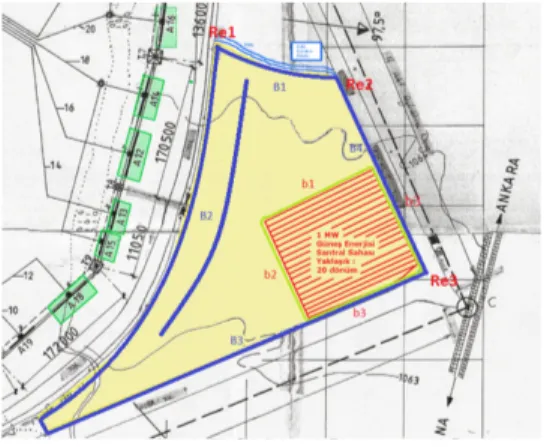
Fig. 1. Map showing two candidate areas for solar panel installation.
demonstrated through the measurement and the simulation of electric fields. The simulations are carried out in 4nec2 [8]. The electric fields are then compared with the ICRINP guidelines for the determination of regions where the fields are higher than human exposure limits.
II. MEASUREMENTS ANDSIMULATIONS
The setup for the broadcasting of Turkish short-wave radio signals consisting of transmitters, antennas, towers and trans-mission lines are spread on a wide area. It is the place from where radio signals are broadcast to several countries around the world using different frequencies varying in the range 1-30 MHz. In order to broadcast radio signals, some of the transmitters are turned on and off. For a particular transmitter or antenna, the maximum input power level is around 500 kW. The two candidate areas (yellow and red color) for the installation of solar panels are shown in Fig. 1.
The transmitting antenna arrays which are predicted to have dominant effects on the designated areas are A12, A13, A15,
A16 and A18 (see Fig. 1). The basic element used in these
antenna arrays is folded dipole antenna. The antenna arrays consist of 2 x 4 folded dipole elements and geometry of A12
constructed in 4nec2 is shown in Fig. 2. The height of the antenna from the ground plane is 9 m. Rest of the antennas are similar in shape to A12 but with different dimensions. These
Fig. 2. Geometry of A12in 4nec2.
Fig. 3. Measured E-field of A12in the yellow region.
antenna arrays are studied via simulations and measurements in terms of the level of electric field they produce on the yellow and red regions.
1) Yellow Region: The boundaries of the yellow region are B1, B2, B3, B4 and measurements are started from a reference points Re1 (for boundaries B1 and B2), Re2 (for boundary B4) and Re3 (for boundary B3) as shown in Fig. 1. The measured electric field in the case when only A12 is active is shown
in Fig. 3. The plot shows that in the yellow region, at some boundaries the average electric field is beyond ICNIRP limits: For instance at a distance of 25 m from B2 boundary the average electric field when only A12is turned on is around 44
V/m. In case when the other transmitters are also turned on, the total electric field at that point will be higher than 44 V/m. According to ICNIRP guidelines, the human safety limits are 87/f1/2 V/m and 28 V/m in the range 1 10 MHz and 10 -400 MHz, respectively [1]–[3].
Fig. 4 shows simulated instantaneous electric field produced by A12 and A13 in 4nec2. The E-fields from A12 and A13
are observed to be very strong violating the threshold human exposure limits of ICRINP. In the light of ICRINP guidelines, the simulated electric field in yellow region are also seen to be beyond the limits.
2) Red Region: The dimensions of the red region are 150 m x 150 m. The E-field measurements were performed in this area with 30 m step size. The measured E-field from the antennas A12, A13, A15, A16and A18are shown in Fig. 5. The
Fig. 4. Simulated E field of A12and A13in the yellow region.
Fig. 5. Measured E-field of A12, A13, A15, A16and A18in the red region.
Fig. 6. Simulated E-field of A12and A13in the red region.
measured E-field is stronger at the corner of the red region which is close to the radiating antennas. It can be seen from the plot that the average E-field is below the ICRINP human exposure limits. However, the instantaneous E-field may be larger than the threshold values. Moreover, simulated E-fields from only two antennas are also stronger at the same corner but slightly below the ICRINP limits. If the E-fields produced by the other antennas are taken into account in the simulation, then the total E-field is expected to exceed the ICRINP limits. Therefore, it can be deduced that the red region is also not suitable in terms of human safety.
3) Effect of the Solar Panel Metal Frames: To see the effect of the metal frames on the radiation patterns of the short-wave
Fig. 7. Structure and 3D radiation pattern of A12.
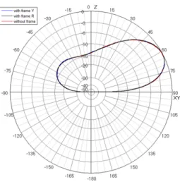
Fig. 8. Effect of the solar panel metal frames on the vertical pattern of A12.
Fig. 9. effect on the horizontal pattern of the antenna
antenna array, a structure made of wires was created in 4nec2 to mimic the frame and it was placed in both the yellow and
the red regions separately at a height of 2.5 m from the ground plane. The 3D radiation pattern along with antenna structure and metal frame are shown in Fig. 7. It can be concluded that the metal frame has no significant effect on the radiation patterns of the antenna as can be seen from the vertical and horizontal patterns of the antenna illustrated in Fig. 8 and 9, respectively.
III. CONCLUSION
An experimental study for the feasibility of installation of solar panels on two designated areas on a short-wave radio transmitter station is carried out via on-site measurements and computer simulations and the results are compared with the human exposure limits of ICRINP. It is concluded that the electric field in the two regions is above the human exposure limits. However, the radiation patterns of the antenna are not affected significantly by the metal frames of the solar panels in the two candidate areas.
ACKNOWLEDGMENT
The authors would like to thank Tubitak (The Scientific and Technological Research Council Of Turkey) under the scholarship scheme 2215 and TRT for their financial support to produce this useful work.
REFERENCES
[1] ICRINP. (1998), “Guidelines on limits of exposure to time-varying electric, magnetic and electromagnetic fields (1 Hz - 300 GHz)”, Health Physics, no. 74, pp. 494 - 522.
[2] ICRINP. (2009), “Exposure to high frequency electromagnetic fields, biological effects and health consequences (100 kHz - 300 GHz)”, Germany: Oberschleißheim.
[3] ICRINP. (2010), “Guidelines on limiting exposure to time-varying electric and magnetic fields (1 Hz - 100 kHz)”, Health Physics, no. 99, pp. 818 - 836.
[4] N. Cherry, “Health Effects in the vicinity of Radio/TV towers and mobile phone base stations”
[5] Y. Shimizu, K. Shigeta, K. Yukawa, T. Nakamura, M. Mikkaichi, Y. Nagasawa and R. Sato, “Analysis of skew antenna around a square tower for UHF TV broadcasting”, IEEE Transactions on Antennas and Propagation, vol. 36, no. 7, pp. 927 - 935, Jul. 1988.
[6] A. A, Ali, “Analysis and design of broadcast tower antenna systems,” M.S. thesis, Dept. Elect.& Electron. Eng., Bilkent Univ., Ankara, Turkey, 2014.
[7] W. Sheng and L. Erping, “Simulation of a Communication Antenna Sys-tem Electromagnetic Radiation and Coupling”, International Conference on Microwave and Millimeter Wave Technology Proceedings, pp. 363 -366, 2000.
[8] A. Voors, “NEC based antenna modeler and optimizer”, [Online]. Avail-able: http://www.qsl.net/4nec2/.


