IS S N 1 3 0 3 –5 9 9 1
KINEMATICAL MODELS OF THE LOCK MOTIONS
SEMRA SARAÇO ¼GLU AND BÜLENT KARAKA¸S
Abstract. In this study, mathematical modelling of lock and key mechanisms is focused and the kinds of motions of the structures are studied. The basic process principle of the lock and key mechanisms mathematically modelled in mechanic and kinematic are brought up. In this modelling, it is shown mutually as the movement the moving part produces or the movement the part setting into motion (K; A).
1. INTRODUCTION
1.1. Rotation. If X = (x; y) are the coordinates of a point P 2 R2 in the moving body measured in the coordinate frame M , then the coordinates of P measured in coordinate frame F can be given by
D : F ! M: This transformation is given by
~
X = [A]~x + d;
where ~x is the coordinate vector of a point in M and ~X is the coordinate vector of the same point but measured in F . If the dimension of the moving body is n ( usually n = 2 or 3 ), then [A] is an n n matrix and d is n-dimensional vector. Let n = 2 , so
[A] = cos sin
sin cos ; d = 8 > < > : d1 d 2 9 > = > ;:
The pair (A; d) de…nes this transformation, and is called a planar displacement [2]. The matrix [A] has [A]T as its inverse, therefore it is an orthogonal matrix; and,
because its determinant is 1, it de…nes a rotation. It is interesting to examine the 2 2 orthogonal matrices that are not rotations [2].
Received by the editors Oct. 14, 2009, Accepted: May. 25, 2010. 2000 Mathematics Subject Classi…cation. 70B15.
Key words and phrases. Lock, key, motion, kinematic, rotation, transition.
c 2 0 1 0 A n ka ra U n ive rsity
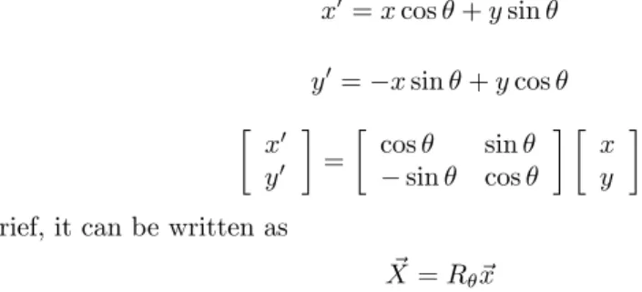
Let R (0) be the degree rotation leaving the O point …xed. Then the rotation equations for n=2 can be given by
x0 = x cos + y sin y0= x sin + y cos x0 y0 = cos sin sin cos x y In brief, it can be written as
~
X = R ~x
where R matrix is a matrix having the RT = R 1property and R is an orthogonal
matrix.
Figure 1. The plane evident with X2; X3.
The dx line evident with ~X vector is called the rotation axis of the rotation R.
De…nition 1.1. Let f : I R ! R show a given function. The matrix A deter-mined by
[A] = cos(( 1)
[jf (x)j]: (x)) sin (( 1)[jf (x)j]: (x))
sin (( 1)[jf (x)j]: (x)) cos(( 1)[jf (x)j]: (x))
Example 1.2. Any rotation series for …ve handled can be shown by identi…ed code matrix as: If f : R ! R, let
f (x) = 8 > > > > < > > > > : 1; x = 0 2; x = 12 3; x = 1 4; x = 2 1; x = 14 and then, [A] = cos(( 1) ([jf (x)j]:2 x) sin (( 1)[jf (x)j]:2 x) sin (( 1)[jf (x)j]:2 x) cos(( 1)[jf (x)j]:2 x) [A1] = cos 0 0 sin 00 sin 00 cos 00 = 1 0 0 1 [A2] = cos sin sin cos = 1 0 0 1 [A3] = cos ( 2 ) sin ( 2 ) sin( 2 ) cos ( 2 ) = 1 0 0 1 [A4] = cos (4 ) sin (4 ) sin(4 ) cos (4 ) = 1 0 0 1 [A5] = cos ( =2) sin ( =2) sin( =2) cos ( =2) = 0 1 1 0 is obtained.
2. THE MATHEMATICAL MODELLING OF THE LOCK MOTIONS In this chapter, …rst, the lock mechanisms will be categorized by being studied in terms of motion kinds. There are basically two motions full…lling the locking process. These are the motions that the moving part does and that put into motion does.Accordingly, the lock and key duet makes up a mechaism by moving bound to each aother. The mutual motion of this duet is kinematically based on the rotational and transitional motions. As the combination of rotations and translations, it is seen that di¤erent kinds of motions appear. Accordingly, if the key and lock duet (K; A) is expressed, it is understood that
(K; A) : (H1; H2)
H1 : The motion that the tumbler in the lock does
Here H1and H2are combination of one or more of the motions of T : transition,
R: rotation, RT : rotational transition, DH: degenerate motion, V : screw motion. According to all those, the lock mechanisms can be grouped like the following in point of kinematic view with 6 di¤erent motion kinds:
1. (K; A) : (T; T ) Lock motion, 2. (K; A) : (R; R) Lock motion, 3. (K; A) : (T; RT ) Lock motion, 4. (K; A) : (R; V ) Lock motion, 5. (K; A) = (DH; T ) Lock motion, 6. ((K1; K2; K3; K4); A) : ((T1; T2; T3; T4); R) Lock motion.
7. Multi and total motion of the lock mechan
3. THE STUDY OF THE KINEMATICAL MODELS OF THE LOCK MOTIONS
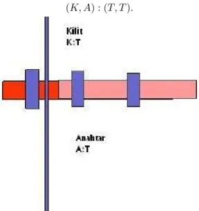
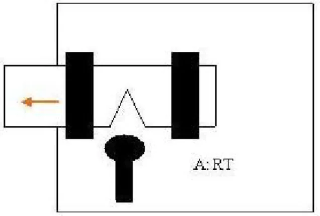
3.1. (K; A) : (T; T ) Lock motion. The lock is the one having the simplest struc-ture in the lock mechanism motion kinds. In this kind of motion, both the part taking over the locking function and the motion applied on this part are directional motion. When whole of the mechanism is regarded, it is observed that the motion appeared is a transitional motion. The model of the concerning mechanism is,
(K; A) : (T; T ):
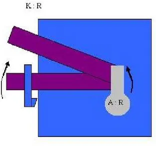
3.2. (K; A) : (R; R) Lock Motion. In this mechanism, the motion starts by means of a key. The structure putting the tumbler into motion creates a rotation motion. Accordingly, the motion that the tumbler brings up is a rotation. The model of this system can be given with
(K; A) : (R; R):
The matrix form of the motion with center 0 = (0; 0) is given by
[R] = cos sin
sin cos The motion belonging to this system is as in Figure 3
Figure 3. Rotational motion lock mechanism
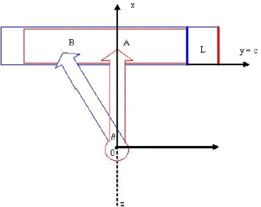
3.3. (K; A) : (T; RT) Lock Motion. In this kind of motion, there is a di¤erent kinematic …xing. The mechanism does a whole transition motion but the source of this transition motion is the rotational motion that the key creates. Since the motion part of the moving part of the lock is limited, the key actually does a transitional rotation.
Figure 4 Rotational transition motion system
Let the rotation axis of the key be as z axis, the rotation point be as the origin point and the rotation plane as x y plane. The closing point of the lock goes from the location A to location B by the e¤ect of the lock. Since the joint will move in a certain slide on the lock, it creates a transition motion. The transition vector is (L; 0). Each point on the key joint has the rotation of
(x; y) ! (x L; y): Accordingly, the matrix of this motion is as
[K] = 2
4 cossin sincos dd12
0 0 1 3 5 2 4 xy0 1 3 5 = 2 4 xy0 L sin 1 3 5 : Since the degree is evident, (d1; d2) transition vector must be calculated,
x cos + y0sin + d1 = x L sin
x sin + y0cos + d2 = y0
And then, d1and d2 transitions are obtained as,
d1 = (1 cos )x (y0+ L) sin
d2 = xs 2 + (1 cos )y0
Accordingly, the model is evident as
Figure 5. Rotational transition motion system -2
3.4. (K; A) : (R; V) Lock Motion. Another kind of the lock motions is seen in the screw motioned lock mechanism.Key is in a shape of screw here, and does a helix motion. The key entering the system with a helix motion results in releasing squeezing the string mechanism. Such a motion allows the system to be opened. Therefore,
(K; A) : (R; V ) equality can be written for this motion.
Figure 6. Inside structure of the screw motioned lock mechanism [5] 3.5. (K; A) = (DH; T) Lock Motion. The piece having the role of a key in this mechanism leaves the pieces hindering the mechanism to be opened inactive by forcing on the free positioned the string. Therefore, the pieces in the mechanism can be separated from each other and the system gets opened. A di¤erent kind of motion which we can also call obstacle canceller, kind of lock shows itself in this lock system.
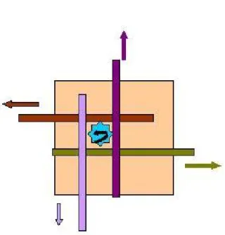
3.6. ((K1; K2; K3; K4); A) : ((T1; T2; T3; T4); R) Lock Motion. It is possible
to name this kind of motion as multi motioned-single motioned mechanism. A multi joined lock mechanism with a motion from a single center is simultaneously a mechanism in which a four-directed lock motion is done. Here four systems are put into motion in a single stage with a single lock motion shown in type 3. This system has not only sprang mechanisms but also pinned and obstacled key kinds developed today. The spring in the system allows the mechanism to be opened even without using a lock pick. However, pinned and obstacled keys cancel this problem Rotational transition motion in four di¤erent direction is taken as K1; K2; K3; K4.
In this case we have [K1]=
2
4 cossin sincos dd12
0 0 1 3 5 2 4 xy0 1 3 5 = 2 4 xy0 L sin 1 3 5
x cos + y0; sin + d1 = x L sin
Therefore, d1and d2 transitions are
d1 = (1 cos )x (y0+ L) sin
d2 = x sin + (1 cos )y0
The second rotation + transition motion From the equations
[K2] =
2
4 cossin sincos dd12
0 0 1 3 5 2 4 xy0 1 3 5 = 2 4 x + L siny0 1 3 5 we have
x cos y0; sin + d1 = x + L sin
x sin y0cos + d2 = y0
d3and d transitions are found as
d3 = ( 1 cos )x + (y0+ L) sin
d4 = x sin + ( 1 + cos )y0
The third rotation + transition motion From the equations
[K3] =
2
4 cossin sincos dd12
0 0 1 3 5 2 4 xy0 1 3 5 = 2 4 xy0 L sin 1 3 5 we have x0cos + y sin + d1 = x0
x0sin + y cos + d2 = y L sin
Thus d5and d6 transitions are found as
d5 = (1 cos )x0 y sin
d6 = (1 cos )y + (x0 L) sin
The fourth rotation + transition motion From the equations
[K4] =
2
4 cossin sincos dd12
0 0 1 3 5 2 4 yx0 1 3 5 = 2 4 xy + L sin0 1 3 5 we have x0cos + y sin + d1 = x0
d7and d8 transitions are as the following
d7 = ( 1 + cos )x0 y sin
d8 = ( 1 cos )y + (L x0) sin
Figure 7. Rotational transition motion in four di¤erent direction from a single center
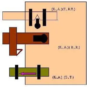
Figure 8. Summary of three di¤erent motion systems.
4. CONCLUSION
In this study, kinds of motions in di¤erent kinds of lock mechanisms have been studied by making a kinematical modelling description The relations and di¤er-ences between the kinds of motions were brought in. The matrices and func-tions belonging to rotafunc-tions and transifunc-tions in the systems were described. [K1],
[K2], [K3], [K4] matrices belonging to the four di¤erent rotational transitions and
d1; d2; d3; d4; d5; d6; d7; d8 transitions from a single center have been obtained.
ÖZET:Bu çal¬¸smada kilit ve anahtarlar¬n matematik ve kinematik modellemeleri çal¬¸s¬ld¬. Matematik ve kinematik aç¬dan modelle-menin temel i¸slemi öncelikle mekanizmalar¬s¬n¬‡and¬rmakt¬r. Mod-ellemede kilit ve anahtarlar (K; A) gösterimi kullan¬larak s¬n¬‡and¬r¬ld¬.
References
[1] Bottema, O., Roth, B., 1979. Theoretical kinematics. North-Holland Publishing Company, New York. 557.
[2] McCarthy, J. Micheal, 1990. An Introduction to Theoretical Kinematics . MIT Press, Cam-bridge. 130.
[3] Niku, Saed B.Niku, 2001. Introduction to Robotics. Prentice Hall Press , New Jersey. 349. [4] O’Neil, Peter V.,1987.Advanced Engineering Mathematics. Wadsworth
[5] Tanavoli, P., 1976. Locks from Iran, Smithsonian Institution, Iran. 151.
Current address : Semra Saraço¼glu, Department of Mathematics Faculty of Education, Siirt University, S·I·IRT TÜRK·IYE
![Figure 6. Inside structure of the screw motioned lock mechanism [5] 3.5. (K; A) = (DH; T) Lock Motion](https://thumb-eu.123doks.com/thumbv2/9libnet/4094275.59423/8.918.221.703.194.465/figure-inside-structure-screw-motioned-mechanism-lock-motion.webp)