Magn Reson Med. 2021;85:1727–1741. wileyonlinelibrary.com/journal/mrm
|
1727 F U L L PA P E REigenmode analysis of the scattering matrix for the design of
MRI transmit array coils
Ehsan Kazemivalipour
1,2|
Alireza Sadeghi-Tarakameh
1,2|
Ergin Atalar
1,21Department of Electrical and Electronics Engineering, Bilkent University, Ankara, Turkey 2National Magnetic Resonance Research Center (UMRAM), Bilkent University, Ankara, Turkey
© 2020 International Society for Magnetic Resonance in Medicine
Correspondence
Ergin Atalar, Department of Electrical and Electronics Engineering, Bilkent University, 06800 Bilkent, Ankara, Turkey.
Email: ergin@ee.bilkent.edu.tr
Purpose: To obtain efficient operation modes of transmit array (TxArray) coils using
a general design technique based on the eigenmode analysis of the scattering matrix.
Methods: We introduce the concept of modal reflected power and excitation eigenmodes,
which are calculated as the eigenvalues and eigenvectors of SHS, where the superscript H denotes the Hermitian transpose. We formulate the normalized reflected power, which is the ratio of the total reflected power to the total incident power of TxArray coils for a given excitation signal as the weighted sum of the modal reflected power. By minimizing the modal reflected power of TxArray coils, we increase the excitation space with a low total reflection. The algorithm was tested on 4 dual-row TxArray coils with 8 to 32 channels.
Results: By minimizing the modal reflected power, we designed an 8-element
TxArray coil to have a low reflection for 7 out of 8 dimensions of the excitation space. Similarly, the minimization of the modal reflected power of a 16-element TxArray coil enabled us to enlarge the dimension of the excitation space by 50% compared with commonly employed design techniques. Moreover, we demonstrated that the low total reflected power for some critical excitation modes, such as the circularly polarized mode, can be achieved for all TxArray coils even with a high level of coupling.
Conclusion: Eigenmode analysis is an efficient method that intuitively provides a
quantitative and compact representation of the coil’s power transmission capabili-ties. This method also provides insight into the excitation modes with low reflection.
K E Y W O R D S
eigenmode analysis, modal reflected power, total reflected power, transmit (TxArray) array coil
1
|
INTRODUCTION
RF transmit array (TxArray) coils are being extensively uti-lized in ultrahigh field MRI to overcome different issues, such as RF excitation inhomogeneities.1-8 TxArray coils can be very useful for conventional high-field scanners because they provide additional degrees of freedom to the designers of pulse sequences and enable RF shimming while attempt-ing to suppress specific absorption rate9-11 hotspots. Besides, these degrees of freedom are useful for increasing the power
efficiency12-14 and accelerating RF-intense applications.15 TxArray coils can also be beneficial for the implementation of the implant-friendly mode.16-19
The performance of TxArray coils significantly profits from parallel transmit technology if the coil designs satisfy particular requirements, such as low mutual coupling be-tween individual array elements and sufficient interaction with samples to ensure sufficiently high power efficiency. High coupling among array elements makes power deliv-ery to the subject challenging and, therefore, is considered a
major design issue.14 A variety of strategies have been tested to reduce mutual coupling, including geometrically overlap-ping the nearest-neighbor array elements20,21; inserting either capacitors or inductors between 2 nearest-neighbor array ele-ments22-26; and adding a decoupling multiport network before TxArray coil ports.27,28
Increasing the number of transmit elements can enhance the capability of TxArray coils in terms of RF shimming and homogeneity. The problem of mutual coupling reduction becomes more complex as the number of array elements in-creases due to the need for more decoupling components and longer cables to decouple nonadjacent elements, which are distantly located.14,29,30 Considering the cost of high-power RF amplifiers, improvements in the incremental performance by further transmit elements with realistic assumptions of power budget for particular TxArray coil geometries and con-figurations should be determined. Theoretically, the power efficiency of a TxArray coil under single-channel excitation depends on the amount of power coupled to other transmit elements and is reflected back to the amplifier. The reflected power does not produce the B+1 field31 within the sample and may cause damage to the amplifiers.14,32 In this situation, proper matching, tuning, and decoupling of a TxArray coil produce higher transmitted power from the amplifier to the transmit elements and lower reflected power from all trans-mit elements.14,33 For a TxArray coil with coupled transmit elements under multichannel excitation, the total reflected power depends on the phases and amplitudes of the RF exci-tation signals, as well as the levels of matching, tuning, and decoupling. Although multiple studies focused on optimizing the excitation signals with various strict constraints, includ-ing the power consumption of TxArray coils,14,34-38 catego-rization of the inputs based on the transmitted and reflected power in TxArray coils warrants attention.
Here, we present the concept of excitation eigenmodes to achieve a quantitative and compact representation of the TxArray coil’s transmission capabilities. For a given set of excitation signals, the total power transmitted to a TxArray coil can be analyzed using its scattering matrix (S-matrix), which can be determined as a relationship between the inci-dent waves and reflected waves. The eigenmode analysis of
S-matrix provides insight into the excitation signals with a
low level of reflected power. It offers a simple tool for quan-tifying, comparing, and optimizing the performance of the TxArray coils.
An ideal TxArray coil in terms of the power efficiency will have a zero total reflected power for all incident waves, which requires a zero S-matrix. Due to the practical limita-tions and imperfeclimita-tions in matching and decoupling, S-matrix cannot be zero. However, the S-matrix elements can be min-imized by adjusting the geometrical parameters or capacitor values of the coil using an optimization process. In this pro-cess, the optimization criterion is fundamental and affects the
performance of the coil.39 The vast majority of studies con-centrated on minimizing the magnitude of S-matrix elements without considering the excitation signals.30,40-42 However, the excitation signals have a significant role in determining the total transmitted and reflected power levels.39 For a given TxArray coil, the reflection can be high for some excitation signals but low for some others. Here, we propose that the eigenmode analysis, looking at the S-matrix as a whole, captures more than just looking at the S-matrix elements individually. In this new matrix analysis, in addition to the magnitude of the S-matrix elements, their phases are also in-cluded, which were previously ignored. The insight provided by this approach can be used to minimize the total reflected power for larger sets of excitation signals by adjusting the TxArray coil design parameters. The novel design strategy utilized in this work demonstrates the possibility of obtaining very low total reflected power for specific sets of excitations, even for TxArray coils with a non-zero S-matrix.
In this study, we provide the theory and concept of the S-matrix eigenmode analysis, discuss the details of the TxArray coil design, and explain the optimization strategy used to adjust the capacitor values to minimize the total reflected power. We provide some simulation and experiment results on 4 dual-row TxArray coils with a different number of chan-nels for imaging at 3 Tesla scanners. These coils43,44 have a significant potential to replace the conventional body coils because they can perform similar to the traditional birdcage coils45-47 if they are driven in the circularly polarized (CP) form but also provide additional degrees of freedom for many valuable applications of the TxArray coils.
2
|
THEORY
The S-matrix describing a TxArray coil characterizes all the power interactions between its input ports. For a generic TxArray coil consisting of N transmit elements, the S-matrix is represented as b = Sa, where a and b are the vectors of the incident and reflected waves, respectively, defined as
where V and I are the vectors of RMS port voltages and cur-rents. Z0 is the reference impedance and is chosen as 50 ohms in this study. With this formulation, the total average power trans-mitted to a TxArray coil with lossless transmission lines can be written as48
where the superscript H denotes the Hermitian (conjugate) transpose, and U denotes the identity matrix. Equation (2) (1) a = 1 2√�ℜ{Z0}� (V + Z0I) and b = 1 2√�ℜ{Z0}� (V − Z∗0I), (2) PT t = a H a − bHb = aH(U − SHS)a,
expresses the net transmitted power as the difference between the incident power and the reflected power, which can be quan-tified as PT
i = a
Ha and PT r= b
Hb, respectively. A perfect design
has 100% transmitted power and no reflected power, which does not occur when the transmit coil elements are coupled. We define the normalized reflected power as the ratio of the total reflected power to the total incident power that can be charac-terized as a function of the excitations and S-matrix
λ(a) can be minimized to ensure high transmit efficiency.
Examining SHS can provide information on the total
in-cident and reflected power of a TxArray coil.49,50 SHS is a Hermitian matrix, which is therefore diagonalizable by a uni-tary similarity transformation.51 Hence,
where Q is a unitary matrix (ie, QQH = QHQ = U) formed by the eigenvectors (qn) of SHS. Λ is a diagonal matrix formed by
the eigenvalues (λn) of SHS.
If the TxArray coil is excited in such a way that the vector of the incident waves is equal to the nth eigenvector of SHS, that is, a = qn, then the normalized reflected power yields
because [SHS]qn = λnqn. It should be noted that all eigenvalues are positive real with values less than or equal to one.52 The ei-genvectors of SHS are orthogonal52 and represent the excitation vectors of the TxArray coil. Therefore, they shall be called the
excitation eigenmodes of the TxArray coil, and the eigenvalues
of SHS shall be called the modal reflected power values of the
TxArray coil. The normalized reflected power in the case of an arbitrary vector of incident waves, which can be uniquely ex-panded as a sum of the distinct eigenmodes, that is, a =∑Nn= 1wnqn= Qw, where w = [ w 1w2… wN ]T is the vec-tor of the expansion coefficients, can be expressed as follows
Equation (6) shows that the normalized reflected power can be represented as the normalized weighted sum of the modal reflected power values. Because the form of λ(a) is a Rayleigh quotient,53 its values are always between the small-est and largsmall-est λn values.49 To obtains an ideal TxArray coil
with zero total reflected power for any arbitrary inputs, all eigenvalues of SHS must be zero, which does not appear to be
feasible. However, the parameters in determining SHS can be
adjusted to minimize all eigenvalues and achieve a low total reflected power for a broader set of incident waves.
3
|
METHODS
3.1
|
λ-opt design strategy
In this study, we employed a design strategy based on the minimization of the normalized reflected power to obtain the capacitor values of TxArray coils, known as λ-optimization (λ-opt). This strategy minimizes the normalized reflected power for excitation eigenmodes as well as for the CP excitation vec-tor, that is, λCP. Minimizing λCP provides the opportunity to
compose the CP mode from the most efficient excitation eigen-modes. However, the optimization problem was formulated as
where c is the vector of the capacitor values and N is the total number of channels. αn and αCP represent the weights for each
term. A constraint can be added to Equation (7) to obtain de-sired modes of operations. We used this general formulation under 3 specific cases:
These 3 different minimization cases were employed to investigate the impact of the added constraint and weighting coefficients on the optimization results. To compare the per-formance of the λ-opt strategy, we also implemented the con-ventional minimization strategy,13,33,54,55 which is based on minimizing the magnitude of the S-matrix elements individ-ually (S-opt). For this, we minimized the difference between the actual and desired S-matrices, as described in Ref. 55. Therefore, this optimization criterion was formulated as
The added constraint puts an upper limit on the diagonal elements of S-matrix. Note that ∑N
n= 1 ∑N m= 1�s𝑚𝑛�2, which (3) 𝜆(a) = PT r PT i =b Hb aHa= aHSHSa aHa . (4) SHS = QΛQH, (5) 𝜆(a = qn) =b H b aHa= qH nS HSq n qH nqn =q H n𝜆nqn qH nqn = 𝜆n (6) 𝜆(a) =a HSHSa aHa = wHQHSHSQw wHQHQw = wHQHQΛQHQw wHQHQw = wHΛw wHw = N � n= 1 � 𝜆n �w n ‖w‖ �2� . (7) 𝜆- opt:min c N ∑ n =1 ( 𝛼n𝜆2 n ) + 𝛼𝐶 𝑃𝜆2 𝐶 𝑃, (8) 𝜆- opt: case1 min c 1 N N ∑ n= 1 𝜆2 n+ 𝜆 2 𝐶 𝑃 case2 min c 1 N N ∑ n= 1 𝜆2 n+ 𝜆 2 𝐶 𝑃 s.t. 𝜆𝐶 𝑃≤0.01 case3 min c 1 N N ∑ n= 1 𝜆2 n . (9) S-opt: min c 1 N N ∑ n= 1 N ∑ m= 1 |s𝑚𝑛|2 s.t. |s𝑛𝑛| ≤ −15dB .
is equal to the trace of SHS, can also be calculated as the summation of the λn values51; therefore, the S-opt approach
minimizes the average of the λn values denoted as λav while
limiting the diagonal elements of S-matrix to be equal to or less than −15 dB.
3.2
|
Proposed model for RF TxArray coil
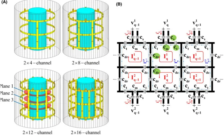
The proposed model and schematic of dual-row (2×-chan-nel) head TxArray coils are shown in Figure 1. These coils have a cylindrical geometry, which is composed of N trans-mit loops with the same dimensional sizes distributed in both the circumferential direction and the z-direction and can be decoupled (approximately) by adjusting the decoupling capacitors placed between the nearest neighbors. In each loop, 5 distinct capacitor values, that is, c = [ c𝑑𝑟c𝑑𝑐ctcmcs], mainly control the performance of the TxArray coils as free design parameters. The chosen structure for the dual-row TxArray coil enables the coil to act like a single-dual-row degenerate birdcage TxArray coil22,23,43,44,56-59 when the mesh currents of the adjacent elements in the axial direction cancel each other in the mid-ring segments of the coil. In the CP excitation mode, both rows are individually excited with identical power and linearly increasing phases, and the
lower-row channels are excited with a 180° phase shift rela-tive to the upper-row channels. When the CP excitation is applied to this coil, it produces a field similar to a conven-tional birdcage coil with a rather uniform B+1 field distribu-tion in a large FOV.
3.3
|
Numerical simulations
Four shielded dual-row TxArray coils at 3 Tesla with 4, 8, 12, and 16 transmit channels in each row were designed and simulated (Figure 1). Additionally, 4 high-pass birdcage coils at 3 Tesla composed of 4, 8, 12, and 16 rungs were simulated (Supporting Information Figure S1) to compare the B+1 pat-terns of the TxArray coils in the CP excitation mode with the traditional birdcage coils. The birdcage coils were driven in the quadrature mode.
All TxArray coil and birdcage coils had a cylindrical geometry with the same dimensions (diameter of 315 mm, length of 270 mm, shield diameter of 408.9 mm, and shield length of 420 mm). All rings and legs were copper strips with a width of 15 mm. All coils shown in Figure 1 were loaded with a uniform cylindrical phantom with a diameter of 160 mm, a length of 350 mm, a conductivity of 0.6 S/m, and a relative permittivity of 80.
FIGURE 1 (A) EM simulation models, and (B) general schematic of dual-row degenerate birdcage TxArray coils. Three axial planes are
shown in (A) to compare TxArray coil fields. Port voltages and mesh currents (red trace) are shown in each loop. I𝐶 𝑃
q (blue trace) denotes mesh
current of CP excitation mode. All coils have same dimensions, are enclosed with same cylindrical RF shields, and are loaded by same uniform cylindrical phantom. CP, circularly polarized; EM, electromagnetic; TxArray, transmit array
Ansys Electronics Desktop 18.2 (Ansys Inc., Canonsburg, PA) was used to implement the numerical simulations at the operation frequency of 123.2 MHz. The conductors were modeled as good conductors,60 and the finite conductiv-ity boundary was defined for them. A sphere with a radius greater than a quarter of the wavelength with the radiation boundary condition was defined as the outer surface of all simulations. Capacitors were adjusted based on the optimiza-tion method explained in the previous secoptimiza-tion using a com-bined finite element method and circuit analysis approach.61 By substitution of all capacitors with equivalent lumped ports, the multiport S-matrices of the loaded TxArray coils were calculated in Ansys HFSS (Ansys Inc.). The multiport
S-matrices were applied to perform the minimization
prob-lem, which was implemented in custom-written MatLab 2018b scripts (MathWorks, Natick, MA) and obtain the op-timal values of the capacitors. These MatLab (Mathworks) scripts are openly available in GitHub at https://github.com/ UMRAM -Bilke nt/Eigen mode-Analysis. In the next step, the multiport S-matrices were exported to ANSYS Designer (Ansys Inc.). The updated port current and voltage values were pushed back to Ansys HFSS (Ansys Inc.) to calculate the distributions of the electric and magnetic fields.
To obtain the capacitor values of the 2 × 4-channel TxArray coil, all 3 different minimization cases of the λ-opt method were studied. The λ-opt (case 1) approach was also used to determine the coil performance as a function of the number of channels. To evaluate the performance of the pro-posed optimization strategy, both the λ-opt (case 1) and S-opt approaches were employed to S-optimize a 2 × 8-channel TxArray coil. The capacitor values in the simulation of the TxArray coils and the high-pass birdcage coils are listed in Supporting Information Table S1.
To obtain more information about the total transmitted power to each TxArray coil, the power loss in phantom and conductors, including the power loss in the shield, were cal-culated. The capacitors are assumed to be lossless. The radi-ation loss was calculated as the difference between the total transmitted power and all other losses.
The B+1 efficiency was evaluated as the average B+1 within a region of interest for a unit total incident power. For com-parison of the performance of the coils, the electromagnetic fields were recorded from 3 different axial planes that pass through the phantom, as shown in Figure 1A.
3.4
|
Measurements
To validate the simulations, the structure of a 2 × 4-channel TxArray coil, which was supported by cylindrical plexiglass with a thickness of 3 mm and an outer diameter of 315 mm (Figure 2A), was constructed. The length of the coil was 270 mm, and all rings and legs were copper strips with a width of 15 mm. The coil’s copper is broken into 56 different sections to distribute the capacitors. Due to practical limitations, the shield was built on another plexiglass in the shape of a right regular dodecagonal prism (Figure 2B). The shield is also constructed of copper strips on the outer side of the frame and slit in 12 equally spaced rectangular sections with di-mensions of 105.5 × 480 mm2 along the axial direction to re-duce gradient-inre-duced eddy currents.62 The neighboring slits were connected with three 2 nF capacitors at positions that face rings of the coil. The strip thickness in both the coil and the shield was 35 μm. The coil was loaded with a cylindrical SNR phantom (3.7 g/L NiCl2.6H2O and 2.4 g/L NaCl) with a diameter of 153 mm. MR electrical properties tomography63
FIGURE 2 Experimental setups. (A) 2 × 4-channel degenerate birdcage head TxArray coil designed and constructed using proposed method.
(B) RF shield with several parallel slots placed on plexiglass in shape of right regular dodecagonal prism. (C) Overview of TxArray coil inside scanner. Coil is loaded with sodium-nickel solution phantom, and body-matrix coil of Siemens scanner (Siemens Healthcare, Erlangen, Germany) is used to pick up MR signals
was used to measure the conductivity of the phantom as 0.62 S/m. Its relative permittivity was assumed to be equivalent to that of water.64,65
To estimate the capacitor values needed for the fabricated coil, an identical loaded 2 × 4-channel TxArray coil with the same 2 nF capacitors on its shield was simulated. The capac-itor values (Supporting Information Table S2) were obtained using the λ-opt (case 1) method. Note that the optimal capac-itors determined by the simulation were finely tuned in the fabricated coil to minimize the error between the simulated and measured |Snn| values, λav, and λCP at 123.2 MHz.
A calibrated Agilent E5061B vector network analyzer (Agilent Technologies, Inc., Baltimore, MD, USA) was used to measure the scattering parameters of the coil. All MR ex-periments were conducted using a 3 Tesla scanner (Magnetom Trio, A Tim System, Siemens Healthcare, Erlangen, Germany) that was equipped with 8 transmit array channels. Each chan-nel utilized a separate amplifier (Analogic Corp., Boston, MA) with adjustable power output with maximum peak power of 8 kW. Accordingly, 8 coaxial cables with adjusted bazooka baluns were used to carry the RF power from the amplifiers to the TxArray coil. The TxArray coil was utilized only in transmit mode without any detuning circuits. A Siemens body-matrix coil, which is a 6-channel standard flexible surface coil with 6 integrated preamplifiers, was used as the receive coil. The possible receive performance degradation due to the lack of de-tuning circuits did not affect our proof of principle experiments. A method based on the Bloch-Siegert shift66,67 was used to acquire the B+1 map at the central axial plane of the coil. The Bloch-Siegert shift was applied by a modified gradient-echo pulse sequence to spins by an off-resonance Fermi pulse. The duration and the off-resonance frequency were, respectively, 8 ms and 2 kHz. The other relevant imaging parameters were TR/TE = 100 ms/12 ms, slice thickness = 5 mm, matrix = 128 × 128, FOV = 300 mm, and number of averages = 1. A mask with a threshold of one-tenth of the maximum B+1 value was applied to the B+1map to minimize the effect of unreliable data (low SNR).
4
|
RESULTS
4.1
|
Simulation results
The performance of all 4 TxArray coils at 123.2 MHz tuned by the different minimization approaches is summarized in Table 1. In this table, all of the λn values, λCP, |Snn| values,
maximum coupling levels, and B+1 efficiencies in the CP exci-tation mode are provided for different solutions. The simula-tion results based on the λ-opt (case 1) approach revealed that the ability to match and decouple the TxArray coils decreases as the number of transmit channels increases, indicated by an increase in the average of modal reflected power values,
λav. Note that this value is also equal to N1 ∑N
n= 1
∑N
m= 1�s𝑚𝑛�2. Moreover, the CP mode B+1 efficiency remains unchanged because λCP was kept reasonably low for all 4 TxArray coils.
For TxArray coils with 8, 16, 24, and 32 transmit channels, 1, 7, 11, and 20 of the excitation eigenmodes have a very high modal reflected power (>0.93), respectively; therefore, these modes hardly contribute to the transmission process. 7, 9, 8, and 8 of the excitation eigenmodes have a total reflec-tion of less than 50% for coils with 8, 16, 24, and 32 chan-nels, respectively. These modes can be regarded as efficient eigenmodes of the TxArray coils, which can span the excita-tion space with low total reflecexcita-tion, and their corresponding eigenvalues are shown in bold in Table 1. Although the num-ber of efficient eigenmodes remains relatively constant as the number of channels increases, the ratio of efficient eigen-modes to all excitation eigeneigen-modes decreases significantly. For coils with 8, 16, 24, and 32 channels, respectively, 88%, 56%, 33%, and 28% of the eigenmodes can be accessed ef-ficiently (≤50%), which indicates that adding channels does not necessarily lead to a proportional increase in the degrees of freedom.
The results (Table 1) also demonstrate that the solution obtained for the 2 × 8-channel TxArray coil by the S-opt approach increases λCP substantially (by 50%) compared to
the solution obtained by the λ-opt method. The increase in
λav and decrease in B+1 efficiency are not very significant
(13% and 9%, respectively). Also, 9 excitation eigenmodes with a total reflection of less than 50% are available with the solution acquired by the λ-opt (case 1) approach. In contrast, in the solution obtained by the S-opt approach, only 6 eigenmodes have this property, indicating that the λ-opt method significantly enlarges the excitation space. For some applications that require more transmitted power or under some hardware limitations, a lower threshold value of modal reflected power can be considered for de-termining the excitation space. Considering an excitation space with a total reflection of less than 40% shows that 8 eigenmodes were available with the solution acquired by the λ-opt approach. In contrast, the S-opt approach offered only 4 excitation eigenmodes.
Moreover, 3 different solutions of the λ-opt approach ob-tained for the 2 × 4-channel TxArray coil have shown that limiting λCP to less than 0.01 (case 2) can increase λav
sig-nificantly (by 18%). Dropping out λCP in the minimization
problem (case 3) did not cause a significant change in λav.
The 2 × 4-channel TxArray coil has only 1 excitation ei-genmode, with a reflection of more than 98% when any of the λ-opt approaches are used. Therefore, the usage of the different cases did not alter the dimension of the excitation space. Furthermore, λCP was changed significantly with the
use of different cases. The results have also shown that the 2 × 4-channel TxArray coil is capable of acceptable levels of matching and decoupling.
TABLE 1
Summary of performance of simulated TxArray coils designed based on different minimization approaches
Minimization Approach 2 × 4-Channel 2 × 8-Channel 2 × 12-Channel 2 × 16-Channel λ-opt λ-opt S-opt λ-opt λ-opt Case 1 Case 2 Case 3 Case 1 Case 1 Case 1 λ1 , λ2 , …, λN 0.02 0.01 0.04 0.10 0.42 0.06 0.65 0.05 0.61 0.99 0.07 0.50 0.98 1.00 0.02 0.01 0.04 0.10 0.98 0.06 0.97 0.05 0.61 1.00 0.07 0.60 0.98 1.00 0.09 0.05 0.08 0.10 0.98 0.15 0.98 0.34 0.63 1.00 0.40 0.60 0.98 1.00 0.09 0.05 0.16 0.10 0.99 0.15 0.98 0.34 0.74 1.00 0.40 0.84 0.99 1.00 0.14 0.28 0.17 0.24 0.99 0.50 0.98 0.49 0.75 1.00 0.43 0.93 0.99 1.00 0.22 0.37 0.17 0.24 1.00 0.50 1.00 0.50 0.97 1.00 0.44 0.93 1.00 1.00 0.30 0.45 0.18 0.40 1.00 0.63 1.00 0.50 0.98 1.00 0.48 0.98 1.00 1.00 0.99 0.98 0.99 0.40 1.00 0.63 1.00 0.50 0.99 1.00 0.48 0.98 1.00 1.00 𝜆𝑎𝑣 = 1 N ∑ N n= 1 𝜆n 0.23 0.27 0.23 0.56 0.64 0.71 0.78 λCP 0.09 0.01 0.17 0.10 0.15 0.05 0.07 |snn | (dB) −23.4 −14.7 −19.7 −9.9 −15.1 −7.7 −5.5 max {| s𝑚𝑛 |} | |m≠ n (dB) −12.3 −10.8 −12.2 −5.9 −4.7 −6.8 −8.4 B
+ efficiency in CP mode at plane 2 1
(μ T/ √ W) 0.63 0.65 0.58 0.63 0.58 0.64 0.64
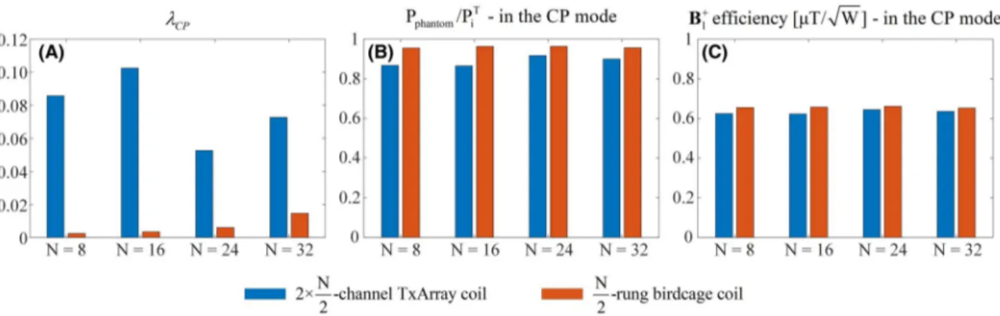
Figure 3 demonstrates the normalized reflected power, the total delivered power to the phantom, and the B+1 efficiency of 4 dual-row TxArray coils and 4 high-pass birdcage coils, all derived in the CP excitation mode. The TxArray coils were designed based on the λ-opt (case 1) approach. Because the number of channels increases in the TxArray coils, λav
increases; however, λCP remains less than 10%, which is
slightly worse than the high-pass birdcage coils. As can be seen in Figure 3B, more than 87% and 95% of the total inci-dent power is delivered to the phantom for the TxArray coils
and the high-pass birdcage coils, respectively, when they are used in the CP mode. The B+1 efficiencies of the TxArray coils and high-pass birdcage coils derived in the CP mode were also very similar (more than 0.62 μT/√W and 0.65 μT/√W, respectively). Note that the slight difference between the CP performance of the TxArray coils and birdcage coils can be eradicated when the λ-opt (case 2) method is used, as can be seen in Figure 4 for the 2 × 4-channel TxArray coil.
The results shown in Figures 4-7 are obtained by simu-lating the 2 × 4-channel TxArray coil with the capacitors
FIGURE 3 (A) Normalized reflected power; (B) total delivered power to phantom; and (C) B+
1 efficiency of N-channel TxArray coil and
N/2-rung high-pass birdcage coil, both derived in CP excitation mode with N = 8, 16, 24, and 32. N-channel TxArray coils were designed based on λ-opt (case 1) approach. opt, optimization
FIGURE 4 (A) B+
1 and (B) electric field patterns of 2 × 4-channel TxArray coil designed based on λ-opt (case 2) approach and 4-rung
high-pass birdcage coil within phantom at 3 different axial planes when both coils were driven in CP excitation mode. Field patterns are normalized by square root of total incident power
determined based on the λ-opt (case 2) approach. Figure 4 also shows the B+1 and electric field patterns of the TxArray coil together with a 4-rung high-pass birdcage coil in the CP
excitation mode normalized by the square root of the total incident power. Both coils generate almost identical field patterns. In Figure 5, the phantom’s dielectric constant was
FIGURE 5 (A) B+
1patterns of 2 × 4-channel TxArray coil designed based on λ-opt (case 2) approach within phantom at central axial plane
(plane 2) when coil was derived in CP excitation mode. (B) B+
1 field distributions at y = 0. Field patterns are normalized by square root of total
incident power
FIGURE 6 (A) B+
1 and (B) electric field patterns of 2 × 4-channel TxArray coil designed based on λ-opt (case 2) approach within phantom for
changed between 20 and 80 to investigate the field focus-ing effect in the 2 × 4-channel TxArray coil. The coil was simulated for each dielectric constant without changing the capacitor values. Figure 5A shows the B+1 patterns within the phantom at the central axial plane (plane 2) when the coil is derived in the CP excitation mode. Also, the field patterns reported in this figure are normalized by the square root of the total incident power. For easier comparison, Figure 5B displays the normalized B+1 field along the x-axis (red dashed line shown in Figure 5A). The B+1patterns for
different dielectric constants demonstrate that a decrease in dielectric constant leads to a smaller field-focusing effect, and thus the B+1 distribution becomes more uniform. As the dielectric constant increases, significant variation in the field patterns can be observed between the center and the surrounding area. This is another indication of the birdcage coil-like behavior of the TxArray coil. The sensitivity of the 2 × 4-channel TxArray coil to the conductivity and diameter of the phantom is shown in Supporting Information Tables S3-S4.
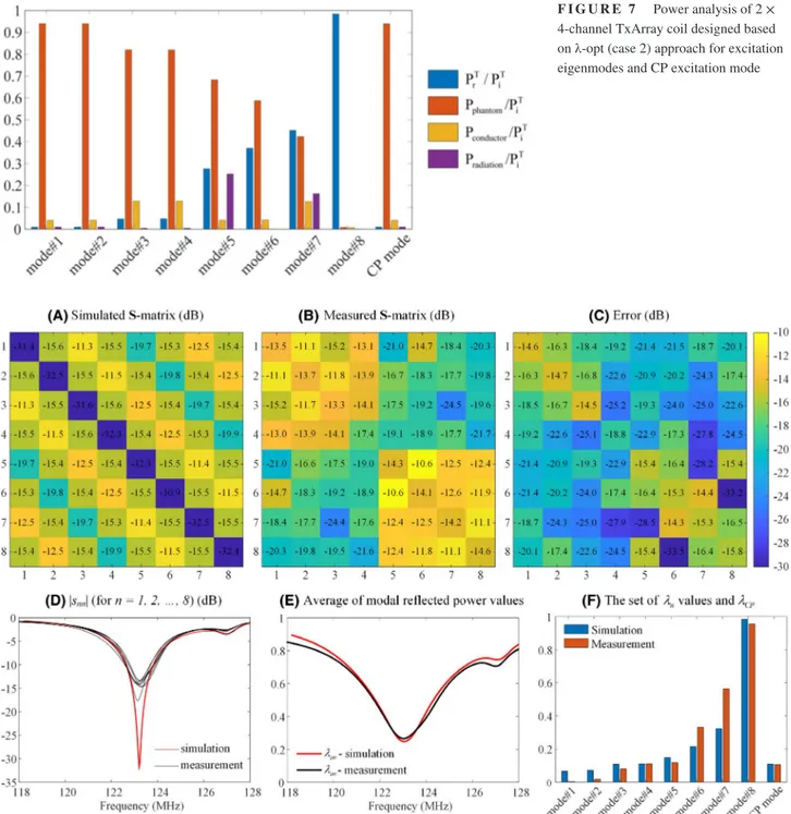
FIGURE 8 (A) Simulated and (B) measured scattering parameter matrices of loaded 2 × 4-channel TxArray coil designed based on λ-opt
(case 1) approach at 123.2 MHz. (C) Difference between simulated and measured S-matrix. (D) |Snn| values for n = 1, 2, …, 8 and (E) λav as
function of frequency. (F) Modal reflected power values of TxArray coil at 123.2 MHz. For comparison, part (F) also shows λCP
FIGURE 7 Power analysis of 2 ×
4-channel TxArray coil designed based on λ-opt (case 2) approach for excitation eigenmodes and CP excitation mode
Figure 6 shows the B+1 and electric field patterns of all 8 excitation eigenmodes of the 2 × 4-channel TxArray coil within the phantom at 3 different axial planes (Figure 1A). For comparison, the B+1 and E field patterns of the CP exci-tation mode are also shown in this figure. The field patterns are normalized by the square root of the total transmitted power. The results indicate that the first and second exci-tation eigenmodes produce linear fields that are perpendic-ular to each other. The fields generated by the CP excitation mode are mainly the quadrature combination of these 2 field patterns.
Figure 7 indicates where the total incident power is con-sumed for each eigenmode. For comparison, this figure also shows the power analysis of the CP mode of excitation. The total reflected power increases in higher modes for a constant total incident power, which causes less power transmission to the TxArray coil. The delivered power to the phantom is also decreased because of lower accepted power in higher modes. For the CP excitation mode, less than 1% of the incident power is reflected; 94% of the incident power is delivered to the phantom. In this mode, only 4% of the incident power is dissipated in the coil conductors, and 1% of the incident power is radiated.
4.2
|
Measurement results
Figure 8A,B provides the simulated and measured S-matrix of the loaded 2 × 4-channel TxArray coil that was designed based on the λ-opt (case 1) approach, which demonstrates a matching level of at least 13.5 dB and decoupling greater than 10.5 dB. Furthermore, Figure 8C illustrates the error matrix that is defined as the difference between the simulated and measured S-matrix and computed as |S𝑠𝑖𝑚𝑢𝑙𝑎𝑡𝑒𝑑− S𝑚𝑒𝑎𝑠𝑢𝑟𝑒𝑑|. Figure 8D,E shows the simulated and measured |Snn|
val-ues and λav as a function of the frequency. The difference
in the matching and decoupling levels observed between the simulated coil and fabricated coil can be attributed to the
imperfections in the construction of the coil. Figure 8F illus-trates the simulated and measured modal reflected power val-ues. For comparison, this figure also shows λCP. Figure 8E-F
reveal that the measured λCP is in good agreement with the
simulated λCP.
Figure 9 compares the B+1 field patterns of the fabricated and simulated 2 × 4-channel TxArray coil at the central axial plane (plane 2) when both coils are derived in the CP exci-tation mode. Phase/magnitude shimming was not performed in the measured B+1pattern. As indicated in Figure 8 for the manufactured coil, the performances of all 8 transmit channels are not precisely the same; therefore, the mode generating the best CP excitation profile for the fabricated coil will not be the same as that defined for the simulated coil. Note that the cor-rect CP excitation mode of the fabricated coil cannot be found by merely evaluating the measured scattering parameters.
5
|
DISCUSSION
In this work, we defined and used the normalized reflected power as the ratio of the total reflected power to the total incident power to analyze the transmitting capabilities of TxArray coils. The excitation eigenmodes (the eigenvec-tors of SHS) were presented as an orthogonal basis for the TxArray coil excitation. The eigenvalues of SHS, λn, were named as the modal reflected power values. We showed that the normalized reflected power for an arbitrary excitation set,
λ(a), can be quantified as the weighted sum of the λn values, which implies that the λn values fully characterize the
trans-mission capabilities of the TxArray coil.
In the literature for general antenna arrays, the concept of the total active reflection coefficient68-70 is used. The magni-tude square of total active reflection coefficient is equal to the modal reflected power; therefore, these concepts can be used interchangeably.
Ideally, zero total reflected power for all possible excitation sets is needed to design an ideal TxArray coil that corresponds
FIGURE 9 Measured (left) and
simulated (right) B+
1 patterns of CP
excitation mode at central axial plane (plane 2) for fabricated and simulated 2 × 4-channel TxArray coil designed based on λ-opt (case 1) approach. Field patterns are normalized by square root of total incident power. In measured B+
1pattern, phase/
to a zero set of λn values, which is possible only if the coil has
a zero S-matrix. This is also the ideal design target to achieve perfect matching and decoupling levels. Due to the practical imperfections, S-matrix cannot be zero; therefore, optimiza-tion algorithms can be configured and run to minimize the S-matrix elements. In current practice, the magnitude of S-S-matrix elements is minimized to match and decouple a TxArray coil. However, minimizing S-matrix elements does not necessarily minimize the λn values because, apart from the amplitude, the S-matrix phase is also effective in determining the λn values. The proposed eigenmode analysis looks at the S-matrix as a whole, captures more than just looking at the S-matrix elements individually. Hence, the minimization of the λn values is a
con-venient approach for the design of TxArray coils.
The eigenmodes with high modal reflected power values hardly contribute to the transmission process and can, to a certain degree, be considered inefficient and impractical. The eigenmode analysis thus provided insight to determine the optimum number of transmit elements. Hence, the num-ber of efficient eigenmodes might be considered as a critical metric to compare the performance of various TxArray coils. Therefore, this study focused mainly on designing TxArray coils by increasing the number of efficient eigenmodes. The set of eigenmodes that has low reflection is considered as the excitation space of the TxArray coil. In the design pro-cess, we want to expand the excitation space. Although there seems to be a limit in this, the coverage of this space can be modified. In our example designs, we made sure that CP excitation lies within this space. It should be noted that with-out limiting λCP, there are many design possibilities for the
TxArray coils proposed in this study in which the CP mode does not lie within the low reflection excitation space. The future users of the proposed algorithm may add additional modes to the optimization process that are significant for the specific design.
For a predesigned TxArray coil, categorizing the efficient and inefficient eigenmodes limits the excitation space to the subset of eigenmodes. In our study, we used 50% as a reasonable number for this limit. In practice, this limit should be defined by the hardware limitations of the overall system, including the available power and the amount of tolerable reflected power. If users, for example, want to conduct RF shimming, the knowl-edge of the excitation space enables users to achieve a proper shim more rapidly within the power limits of the amplifiers.
Assessment of the total power absorbed by the phantom is critically essential. The total absorbed power by the object of interest and the conductor and radiation losses cannot be dis-tinguished by merely assessing the scattering parameters. In the electromagnetic simulation, careful integration within the phantom is necessary. Furthermore, maximizing the power delivered to the object is not directly linked to generating the
desired B+1 field. Linking the excitation space to these param-eters is the subject of future research.
Although we conducted an eigenmode analysis of the
S-matrix of TxArray coils, it was used earlier for other
pa-rameters. For example, the eigenmode analysis was applied to evaluate the SNR behavior of receive array coils,71,72 to improve parallel imaging performance,73 and to attain a ho-mogeneous transmit excitation with low levels of specific ab-sorption rate at ultrahigh field MRI.74 In this study, however, the eigenmode analysis is used to obtain power-efficient op-eration modes of TxArray coils.
6
|
CONCLUSION
In this study, we examined the performance of a dual-row TxArray coil as an example to evaluate the effectiveness of the eigenmode analysis. We demonstrated that the struc-ture chosen for the dual-row TxArray coil could act like a single-row degenerate birdcage TxArray coil by providing the CP excitation field patterns under certain circumstances (Supporting Information Figure S2). Consequently, this coil enables us to benefit from the advantages of the paral-lel transmit technology without losing the advantages of the conventional birdcage coil to obtain rather homogenous ex-citation patterns in a large volume.
For the analysis and design of the TxArray coils, the use of the modal reflected power concept is introduced. The ca-pacitor values were found using our newly developed λ-opt approach. In this approach, the λn values were minimized to
increase the dimension of the excitation space (a subspace composed of the excitation eigenmodes with low total re-flected power values). Additionally, the total rere-flected power for some critical modes of operations, such as the CP excitation mode, can be incorporated as a constraint in the optimization process. To examine the impact of the added constraint and weighting coefficients on the coil performance, 3 different minimization cases of the λ-opt approach were employed. To validate the effectiveness of the λ-opt approach, the optimal design performance of a dual-row TxArray coil achieved by the λ-opt method was compared with the optimal design obtained by the conven-tional minimization approach (S-opt). We showed that the proposed algorithm could increase excitation space, and some critical modes of operations can be achieved without significant reflection.
DATA AVAILABILITY STATEMENT
MatLab (MathWorks) codes that reproduce the results shown in Table 1 are available openly at https://github.com/ UMRAM -Bilke nt/Eigen mode-Analysis.
ORCID
Ehsan Kazemivalipour https://orcid. org/0000-0003-4221-2397
Alireza Sadeghi-Tarakameh https://orcid. org/0000-0001-5718-6553
Ergin Atalar https://orcid.org/0000-0002-6874-6103
REFERENCES
1. Adriany G, Van de Moortele P-F, Wiesinger F, et al. Transmit and receive transmission line arrays for 7 Tesla parallel imaging. Magn
Reson Med. 2005;53:434-445.
2. Adriany G, Auerbach EJ, Snyder CJ, et al. A 32-channel lattice transmission line array for parallel transmit and receive MRI at 7 Tesla. Magn Reson Med. 2010;63:1478-1485.
3. Rietsch SHG, Orzada S, Bitz AK, et al. Parallel transmit capabil-ity of various RF transmit elements and arrays at 7T MRI. Magn
Reson Med. 2018;79:1116-1126.
4. Avdievich NI, Hoffmann J, Shajan G, et al. Evaluation of trans-mit efficiency and SAR for a tight fit transceiver human head phased array at 9.4 T. NMR Biomed. 2017. https://doi.org/10.1002/ nbm.3680
5. Sadeghi-Tarakameh A, DelaBarre L, Lagore RL, et al. In vivo human head MRI at 10.5T: A radiofrequency safety study and pre-liminary imaging results. Magn Reson Med. 2020;84:484-496. 6. Sadeghi-Tarakameh A, Adriany G, Metzger GJ, et al. Improving
ra-diofrequency power and specific absorption rate management with bumped transmit elements in ultra-high field MRI. Magn Reson
Med. 2020;84:3485–3493.
7. Sadeghi-Tarakameh A, Torrado-Carvajal A, Ariyurek C, et al. Optimizing the topography of transmit coils for SAR management. In Proceedings of the 26th Annual Meeting of ISMRM, Paris, France, 2018. p. 0297.
8. Sadeghi-Tarakameh A, Jungst S, Wu X, et al. A new coil element for highly-dense transmit arrays: An introduction to non-uniform dielectric substrate (NODES) antenna. In Proceedings of the 27th Annual Meeting of ISMRM, Montréal, Québec, Canada, 2019. p. 0732.
9. Van den Berg CAT, van den Bergen B, Van de Kamer JB, et al. Simultaneous B-1(+) homogenization and specific absorption rate hotspot suppression using a magnetic resonance phased array transmit coil. Magn Reson Med. 2007;57:577-586.
10. Katscher U, Bornert P. Parallel RF transmission in MRI. NMR
Biomed. 2006;19:393-400.
11. McElcheran CE, Golestanirad L, Iacono MI, et al. Numerical simulations of realistic lead trajectories and an experimental ver-ification support the efficacy of parallel radiofrequency trans-mission to reduce heating of deep brain stimulation implants during MRI. Sci Rep. 2019. https://doi.org/10.1038/s4159 8-018-38099 -w
12. Childs AS, Malik SJ, O’Regan DP, et al. Impact of number of chan-nels on RF shimming at 3T. MAGMA. 2013;26:401-410.
13. Kozlov M, Turner R. Analysis of RF transmit performance for a multi-row multi-channel MRI loop array at 300 and 400 MHz.
Asia-Pacific Microwave Conference. 2011;2011:1190-1193.
14. Guérin B, Gebhardt M, Serano P, et al. Comparison of simulated parallel transmit body arrays at 3 T using excitation uniformity, global SAR, local SAR, and power efficiency metrics. Magn Reson
Med. 2015;73:1137-1150.
15. Setsompop K, Wald LL, Alagappan V, et al. Parallel RF trans-mission with eight channels at 3 Tesla. Magn Reson Med. 2006;56:1163-1171.
16. Eryaman Y, Guerin B, Akgun C, et al. Parallel transmit pulse de-sign for patients with deep brain stimulation implants. Magn Reson
Med. 2015;73:1896-1903.
17. Guerin B, Angelone LM, Dougherty D, et al. Parallel transmission to reduce absorbed power around deep brain stimulation devices in MRI: Impact of number and arrangement of transmit channels.
Magn Reson Med. 2020;83:299-311.
18. Kazemivalipour E, Keil B, Vali A, et al. Reconfigurable MRI technology for low-SAR imaging of deep brain stimulation at 3T: Application in bilateral leads, fully-implanted systems, and surgi-cally modified lead trajectories. Neuroimage. 2019;199:18-29. 19. Golestanirad L, Kazemivalipour E, Keil B, et al. Reconfigurable
MRI coil technology can substantially reduce RF heating of deep brain stimulation implants: First in-vitro study of RF heating reduc-tion in bilateral DBS leads at 1.5 T. PLoS One. 2019;14:e0220043. 20. Roemer PB, Edelstein WA, Hayes CE, et al. The NMR phased-
array. Magn Reson Med. 1990;16:192-225.
21. Keil B, Alagappan V, Mareyam A, et al. Size-optimized 32-chan-nel brain arrays for 3 T pediatric imaging. Magn Reson Med. 2011;66:1777-1787.
22. Sadeghi-Tarakameh A, Kazemivalipour E, Demir T, et al. Design of a degenerate birdcage radiofrequency transmit array coil for the magnetic resonance imaging using equivalent circuit model. In Proceedings of the 34th Annual Scientific Meeting of ESMRMB, Barcelona, Spain, 2017. p. 300-301.
23. Kazemivalipour E, Sadeghi-Tarakameh A, Yilmaz U, et al. A 12-channel degenerate birdcage body transmit array coil for 1.5T MRI scanners. In Proceedings of the 26th Annual Meeting of ISMRM, Paris, France, 2018. p. 1708.
24. Avdievich NI, Pfrommer A, Giapitzakis IA, et al. Analytical mod-eling provides new insight into complex mutual coupling between surface loops at ultrahigh fields. NMR Biomed. 2017. https://doi. org/10.1002/nbm.3759
25. Kazemivalipour E, Sadeghi-Tarakameh E, Atalar E. Optimization of the degenerate birdcage transmit array coil for minimum cou-pling. In Proceedings of the 27th Annual Meeting of ISMRM, Montréal, Québec, Canada, 2019. p. 1604.
26. Kazemivalipour E, Sadeghi-Tarakameh A, Atalar E. Design of transmit array coils for MRI by minimizing the modal reflection coefficients. In Proceedings of the ISMRM & SMRT Virtual Conference & Exhibition, 2020. p. 0762.
27. Jevtic J. Ladder networks for capacitive decoupling in phased- array coils. In Proceedings of the 9th Annual Meeting of ISMRM, Glasgow, Scotland. 2001. p. 17.
28. Lee RF, Giaquinto RO, Hardy CJ. Coupling and decoupling the-ory and its application to the MRI phased array. Magn Reson Med. 2002;48:203-213.
29. Mahmood Z, Guérin B, Adalsteinsson E, et al. An automated frame-work to decouple pTx arrays with many channels. In Proceedings of the 21st Annual Meeting of ISMRM, Salt Lake City, UT, 2013. p. 2722.
30. Avdievich NI, Giapitzakis IA, Pfrommer A, et al. Decoupling of a double-row 16-element tight-fit transceiver phased array for human whole-brain imaging at 9.4 T. NMR Biomed. 2018;31:e3964. 31. Hoult DI. The principle of reciprocity in signal strength calculations:
32. Connell IRO, Gilbert KM, Abou-Khousa MA, et al. MRI RF array decoupling method with magnetic wall distributed filters. IEEE
Trans Med Imaging. 2015;34:825-835.
33. Kozlov M, Turner R. Analysis of RF transmit performance for a 7T dual row multichannel MRI loop array. In Proceedings of the Annual International Conference of the IEEE Engineering in Medicine and Biology Society (EMBC), 2011. p. 547-553. 34. Guérin B, Setsompop K, Ye H, et al. Design of parallel
transmis-sion pulses for simultaneous multislice with explicit control for peak power and local specific absorption rate. Magn Reson Med. 2015;73:1946-1953.
35. Guérin B, Gebhardt M, Cauley S, et al. Local specific absorption rate (SAR), global SAR, transmitter power, and excitation accuracy trade-offs in low flip-angle parallel transmit pulse design. Magn
Reson Med. 2014;71:1446-1457.
36. Brunner DO, Pruessmann KP. Optimal design of multiple-channel RF pulses under strict power and SAR constraints. Magn Reson
Med. 2010;63:1280-1291.
37. Vaughan JT, Garwood M, Collins CM, et al. 7T vs. 4T: RF power, homogeneity, and signal-to-noise comparison in head images.
Magn Reson Med. 2001;46:24-30.
38. van den Bergen B, van den Berg CAT, Klomp DWJ, et al. SAR and power implications of different RF shimming strategies in the pelvis for 7T MRI. J Magn Reson Imaging. 2009;30:194-202. 39. Kozlov M, Turner R. Effects of tuning condition, head size and
position on the SAR of a MRI dual-row transmit array at 400 MHz. In Proceedings Progress in Electromagnetics Research Symposium (PIERS), Taipei, Taiwan. 2013. p. 422-426.
40. Yan X, Ole Pedersen J, Wei L, et al. Multichannel double-row transmission line array for human MR imaging at ultrahigh fields.
IEEE Trans Biomed Eng. 2015;62:1652-1659.
41. Shajan G, Kozlov M, Hoffmann J, et al. A 16-channel dual-row transmit array in combination with a 31-element receive array for human brain imaging at 9.4 T. Magn Reson Med. 2014;71: 870-879.
42. Hoffmann J, Shajan G, Scheffler K, et al. Numerical and ex-perimental evaluation of RF shimming in the human brain at 9.4 T using a dual-row transmit array. MAGMA. 2014;27: 373-386.
43. Alagappan V, Nistler J, Adalsteinsson E, et al. Degenerate mode band-pass birdcage coil for accelerated parallel excitation. Magn
Reson Med. 2007;57:1148-1158.
44. Stara R, Tiberi G, Morsani F, et al. A degenerate birdcage with integrated Tx/Rx switches and butler matrix for the human limbs at 7 T. Appl Magn Reson. 2017;48:307-326.
45. Ibrahim TS, Lee R, Baertlein BA, et al. Computational analy-sis of the high pass birdcage resonator: Finite difference time domain simulations for high-field MRI. Magn Reson Imaging. 2000;18:835-843.
46. Golestanirad L, Kazemivalipour E, Lampman D, et al. RF heat-ing of deep brain stimulation implants in open-bore vertical MRI systems: A simulation study with realistic device configurations.
Magn Reson Med. 2020;83:2284-2292.
47. Kazemivalipour E, Vu J, Lin S, et al. RF heating of deep brain stimulation implants during MRI in 1.2 T vertical scanners versus 1.5 T horizontal systems: A simulation study with realistic lead configurations. In Proceedings of the 42nd Annual International Conference of the IEEE Engineering in Medicine & Biology Society (EMBC), Montréal, Québec, Canada, 2020. p. 6143-6146. 48. Pozar DM. Microwave Engineering. Hoboken, NJ: Wiley; 2012.
49. Volmer C, Weber J, Stephan R, et al. An eigen-analysis of compact antenna arrays and its application to port decoupling. IEEE Trans
Antennas Propag. 2008;56:360-370.
50. Irteza S, Schäfer E, Stephan R, et al. Compact antenna array re-ceiver for robust satellite navigation systems. Int J Microw Wirel T. 2015;7:735-745.
51. Horn RA, Johnson CR. Matrix Analysis. Cambridge, UK; New York, NY: Cambridge University Press; 1985.
52. Lay DC, Lay SR, McDonald J. Linear Algebra and its Applications. Boston, MA: Pearson; 2020.
53. Trefethen LN, Bau D. Numerical Linear Algebra. Philadelphia, PA: Society for Industrial and Applied Mathematics; 1997. 54. Kozlov M, Turner R. Comprehensive analysis of transmit
per-formance for an 8-element loop MRI RF coil at 300 MHz. In Proceedings of the 40th European Microwave Conference, 2010. p. 328-331.
55. Kozlov M, Lucano E, Angelone LM. Effects of tuning condi-tions on near field of MRI transmit birdcage coil at 64 MHz. In Proceedings of the 38th Annual International Conference of the IEEE Engineering in Medicine and Biology Society (EMBC), 2016. pp. 6242-6245.
56. Sadeghi-Tarakameh A, Kazemivalipour E, Demir T, et al. Accelerating the cosimulation method for fast design of transmit array coils: An example study on a degenerate birdcage coil. In Proceedings of the 26th Annual Meeting of ISMRM, Paris, France, 2018. p. 4404.
57. Nistler J, Kurth R, Vester M, et al. B1 inhomogenisation using a multichannel transmit array. In Proceedings of the 14th Annual Meeting of ISMRM, Seattle, WA, USA. 2006.
58. Sadeghi-Tarakameh A, Kazemivalipour E, Gundogdu U, et al. Accelerating the co-simulation method for the design of transmit array coils for MRI. MAGMA. 2020. https://doi.org/10.1007/s1033 4-020-00858 -0
59. Kazemivalipour E, Sadeghi-Tarakameh A, Yilmaz U, et al. Design of an 8-channel transmit array coil using the equivalent circuit model of the manufactured structure. In Proceedings of the 28th Annual Meeting of ISMRM, Virtual, 2020. p. 0758.
60. Balanis CA. Advanced Engineering Electromagnetics. Hoboken, NJ: John Wiley & Sons; 2012.
61. Kozlov M, Turner R. Fast MRI coil analysis based on 3-D elec-tromagnetic and RF circuit co-simulation. J Magn Reson. 2009;200:147-152.
62. Hayes CE, Eash MG, inventors; General Electric Co, assignees. Shield for decoupling RF and gradient coils in an NMR apparatus.
US patent 4642569A. February 10, 1987.
63. Gurler N, Ider YZ. Gradient-based electrical conductivity imaging using MR phase. Magn Reson Med. 2017;77:137-150.
64. Gabriel C, Gabriel S, H. Grant E, et al. Dielectric parame-ters relevant to microwave dielectric heating. Chem Soc Rev. 1998;27:213-223.
65. Winkler SA, Rutt BK. Practical methods for improving B-1(+) homogeneity in 3 Tesla breast imaging. J Magn Reson Imaging. 2015;41:992-999.
66. Sacolick LI, Wiesinger F, Hancu I, et al. B1 mapping by Bloch-Siegert shift. Magn Reson Med. 2010;63:1315-1322.
67. Turk EA, Ider YZ, Ergun AS, et al. Approximate Fourier do-main expression for Bloch-Siegert shift. Magn Reson Med. 2015;73:117-125.
68. Ludwig AC. Mutual coupling, gain and directivity of an array of 2 identical antennas. IEEE Trans Antennas Propag. 1976;24:837-841.
69. Chae SH, Oh SK, Park SO. Analysis of mutual coupling, correla-tions, and TARC in WiBro MIMO array antenna. IEEE Antennas
Wirel Propag Lett. 2007;6:122-125.
70. Hannula J-M, Saarinen T, Holopainen J, et al. Frequency reconfigurable multiband handset antenna based on a multi-channel transceiver. IEEE Trans Antennas Propag. 2017;65: 4452-4460.
71. King SB, Varosi SM, Duensing GR. Eigenmode analysis for under-standing phased array coils and their limits. Concepts Magn Reson
Part B Magn Reson Eng. 2006;29b:42-49.
72. King SB, Varosi SM, Duensing GR. Optimum SNR data com-pression in hardware using an eigencoil array. Magn Reson Med. 2010;63:1346-1356.
73. Wang CS, Qu P, Shen GX. Potential advantage of higher-or-der modes of birdcage coil for parallel imaging. J Magn Reson. 2006;182:160-167.
74. Santini T, Zhao Y, Wood S, et al. In-vivo and numerical analysis of the eigenmodes produced by a multi-level Tic-Tac-Toe head trans-mit array for 7 Tesla MRI. PLoS One. 2018;13:e0206127.
SUPPORTING INFORMATION
Additional Supporting Information may be found online in the Supporting Information section.
FIGURE S1 A, EM simulation models and B, general
sche-matic of four high-pass birdcage coils. All coils have the same dimensions, are enclosed with the same cylindrical
RF shields, and are loaded by the same uniform cylindrical phantoms
FIGURE S2 Surface current density of the 2 × 4-channel
TxArray coil designed based on the λ-opt (case#2) approach and the B+
1-patterns within the phantom for the CP excitation
mode at three different axial planes. Surface current densities and B+
1-patterns are normalized by the square root of the total
incident power
TABLE S1 Optimized capacitor values for the simulated
TxArray coils and high-pass birdcage coils
TABLE S2 Optimized capacitor values for the fabricated and
simulated 2 × 4-channel TxArray coils
TABLE S3 Sensitivity of the eigenvalues to the conductivity
of the phantom
TABLE S4 Sensitivity of the eigenvalues to the phantom
diameter
How to cite this article: Kazemivalipour E,
Sadeghi-Tarakameh A, Atalar E. Eigenmode analysis of the scattering matrix for the design of MRI transmit array coils. Magn Reson Med. 2021;85:1727–1741. https:// doi.org/10.1002/mrm.28533