FAKULTÄT MASCHINENBAU
Master of Science in Manufacturing TechnologyInstitut für Umformtechnik und Leichtbau Prof. Dr.-Ing. Dr. h.c. Matthias Kleiner Prof. Dr.-Ing. Dr.-Ing. E.h. A. Erman Tekkaya
Master Thesis
Numerical Investigation of the Effect of Process
Parameters to Optimize a Superplastic Forming Process
by Elif Sedes
Matriculation no: 162951
Supervisors:
Prof. Dr.-Ing. Dr.-Ing. E.h. A. Erman Tekkaya (IUL) Assist. Prof. Dr. Mehmet Ipekoglu (TAU)
M.S.c. Kerim Isik (IUL) Issued on: 16.11.2016 Submitted on: 26.07.2017
This Master thesis project is carried out by the collaboration between Technical University Dortmund and Turkish-German University. The problem and topic for this thesis are defined by TUSAS Engine Industries (TEI). This thesis has been completed under guidance and constant supervision of Prof. Dr.-Ing. Dr.-Ing. E.h. A. Erman Tekkaya (Institut für Umformtechnik und Leichtbau, TU Dortmund), Assist. Prof. Dr. Mehmet Ipekoglu (Department of Mechatronic Systems Engineering, Turkish-German University) and M.Sc. Kerim Isik (Institut für Umformtechnik und Leichtbau, TU Dortmund).
First and foremost, I would like to express my thankfulness to my supervisor Prof. Dr.-Ing. Dr.-Dr.-Ing. E.h. A. Erman Tekkaya, for motivating and helping me to get knowledge about metal forming technology.
I would like to deeply thank Assist. Prof. Dr. Mehmet Ipekoglu for being my supervisor and his guidance, suggestions and help in each step of my thesis, not only for technical issues but also for encouraging me to succeed my master degree.
I also would like to appreciate M.Sc. Kerim Isik for his suggestions, guidance and help. His insights, supportive criticisms, encouragements and leadings in each step of my study made me always confident.
I also would like to thank my manager Mustafa Tuksal, my colleagues Nitel Muhtaroglu and Nuri Cizioglu for their help, enthusiasm and supportive criticisms.
Finally, yet importantly, I would like to express my appreciation and thanks to my husband Caner Sedes and my parents for their help, understanding and their best wishes for my success. I am grateful for their understanding for the time that I took from them for studying my master thesis. It would be impossible for me to complete my study if I had not felt their support behind me.
Superplastic forming (SPF) is an alternative manufacturing method to produce complex shapes in one step without assembling operations which are not possible with other methods. SPF process enables to get near net shape products without surface finish operation necessities. SPF process can produce parts with nearly 1000% elongations with good mechanical properties. SPF process also reduces the weights of the products because it eliminates assembly processes. Furthermore, SPF process increases cycles of components before failure. Mentioned assets of SPF make it a very important process choice in aviation industry, in which good mechanical properties, low weights and long service lives are required.
The main purpose of this thesis is to investigate process parameters of SPF process for Ti6Al4V material using finite element method (FEM) in order to obtain an optimum process which results in both good product quality and reasonable cost. For this purpose, first analysis results were compared to an experimental study to test accuracy of the used method, next the process parameters were investigated for rectangular and conical parts. Then, a tool was developed to be used in the factory for estimating process time of SPF process with given process parameters. Finally, application of SPF process is conducted for an aircraft blowout door in order to choose an optimum process for production. Keywords: Superplastic Forming, Superplasticity, Finite Element Method, Machine Learning, Data Mining, Aviation, Aerospace
Table of Contents
List of Figures 3
List of Tables 7
Formula Symbols and Abbreviations 9
1 Introduction 12
1.1 Motivation and Objective of the Thesis ... 13
1.2 Outline of the Thesis ... 14
2 State of the Art 16 2.1 Metal Forming ... 16
2.1.1 Bulk Metal Forming ... 17
2.1.2 Sheet Metal Forming ... 18
2.2 Superplastic Forming ... 19
2.2.1 Theory of Superplasticity ... 22
2.2.2 Superplastic Blow Forming ... 27
2.2.3 Superplastic Forming Process Parameters ... 28
2.2.4 Technological and Economical Aspects of SPF Process ... 31
2.3 Information about Superplastic Titanium Alloys ... 33
2.4 Finite Element Formulation of SPF Process ... 34
2.4.1 Implicit and Explicit Approaches ... 35
2.4.2 Finite Element Analysis of SPF Process in ABAQUS Software ... 36
2.4.3 Modelling of SPF Process in ABAQUS Software ... 37
2.5 Machine Learning and Data Mining ... 40
2.5.1 Regression Technique for Machine Learning ... 42
3 Aim and Scope of the Thesis Work 45 4 Investigation of Effect of Process Parameters to SPF Process 47 4.1 Comparison of Finite Element Analysis Study with Experimental Results .. 47 4.2 Investigation of Process Parameters for SPF Process for a Rectangular Part 55
4.2.1 Investigation of the Effect of Loading Profile... 57
4.2.2 Investigation of Effect of Process Temperature ... 61
4.2.3 Investigation of Effect of Strain Rate ... 64
4.2.4 Investigation of Effect of Sheet Thickness ... 68
4.2.5 Investigation of Friction Coefficient ... 70
4.2.6 Investigation of Effect of Die Entry Radius ... 74
4.2.7 Investigation of Forming Behaviour for Different Time Steps ... 75
4.3 Investigation of Process Parameters to the SPF Process for a Conical Part .. 81
4.3.1 Investigation of Effect of Entry Radius of the Die ... 82
4.3.2 Investigation of Effect of Die Aspect Ratio ... 86
4.3.3 Investigation of Effect of Friction Coefficient ... 89
4.4 Comparison of Forming Behaviour of Rectangular and Conical Box Forming………...93 5 Development of an Equation for Estimation of Process Time for SPF Process
by Machine Learning for a Rectangular Box 96
6 Application of SPF Process for an Aircraft Blowout Door 99 7 Cost Analysis of SPF Process for the Factory 106
8 Conclusion 108
Bibliography 111
List of Figures
Figure 2.1: Classification of forming processes (Nptel, 2016)….……….16 Figure 2.2: Basic bulk deformation processes: a) rolling, b) forging, c) extrusion, and d) drawing (Groover, 2012)……….…………..17 Figure 2.3: Basic sheet metal working operations: a) bending, b) drawing, c) shearing: 1) as punch first contacts sheet, and 2) after cutting (Groover, 2012)……….…18 Figure 2.4: Bi-Sn alloy (1950% elongation) (Marinho et al., 2012)………19 Figure 2.5: Development of SPF maximum elongation through years (Marinho et al., 2012)………..………20 Figure 2.6: Simple female forming example for large one-piece truck cab roof in SP5083 alloy (Barnes, 2007)……….21 Figure 2.7: GBS while superplastic deformation (Sieniawski and Motyka, 2007)…..23 Figure 2.8: A typical stress strain rate diagram with change of strain rate sensitivity (Deshmukh, 2003)……….25 Figure 2.9: Relation between flow stress, elongation at fracture and m with strain rate (Marinho et al., 2012)……….26 Figure 2.10: Steps of superplastic blow forming process (N.N., 2008)……….27 Figure 2.11: Effect of grain size to strain rate (Sieniawski and Motyka, 2007)……….30 Figure 2.12: Effect of grain size to working temperature (Sieniawski and Motyka, 2007)………..30 Figure 2.13: Fatigue curve comparison for fan blades for SPF (1) and conventional (2) methods (Afrikantov, 1992)………..……….32 Figure 2.14: Strain rate sensivity diagram of superplastic materials (Ghosh and Hamilton, 1986)……….34 Figure 2.15: Positive normals for general membranes (Deshmukh, 2003)…………..38 Figure 2.16: Coulomb friction in ABAQUS (Deshmukh, 2003)………..39 Figure 2.17: Illustration of data mining process cycle (N.N., 2016)………41 Figure 2.18: Representation of simple linear regression (Analyticsvidhya, 2016)…....43
Figure 2.19: Robustness comparison of LS and LMS regression methods (Dallal,1992)
………...44
Figure 3.1: Process chart for the thesis………..46
Figure 4.1: Finite element model for SPF process ………...49
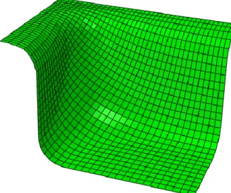
Figure 4.2: Formed rectangular box in ABAQUS for 1.4 MPa constant pressure application……….51
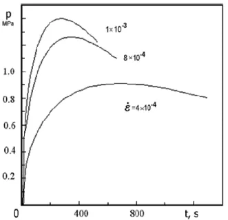
Figure 4.3: Pressure-time cycles applied in experiment for different constant target strain rates (Vasin et al., 2003)………...53
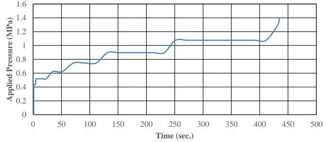
Figure 4.4: Pressure scheme applied to the workpiece for FE simulations………54
Figure 4.5: Rigid surface for the rectangular die………..………….56
Figure 4.6: Assembly of sheet metal and die……….56
Figure 4.7: Deformed shape of sheet metal after 1000 second for constant pressure application for element size 0.8 mm………..59
Figure 4.8: Sheet thickness distribution at blank for constant pressure application…...59
Figure 4.9: Sheet thickness distribution at blank for constant strain rate application...60
Figure 4.10: Pressure schedule for automatic pressure application for strain rate 10-2 1/sec………...61
Figure 4.11: Sheet thicknesses comparison a) for 840° and b) for 900° process temperatures………..……62
Figure 4.12: Comparison of applied pressure for 840 and 900 degrees……….62
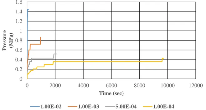
Figure 4.13: Pressure time profiles at different target strain rates………64
Figure 4.14: Minimum sheet thickness-time profiles at different target strain rates...65
Figure 4.15: Sheet thickness distribution at the end of the forming process for a) 10-4 1/sec., b) 5x10⁻⁴ 1/sec., c) 10-3 1/sec., d) 10-2 1/sec. strain rates………...67
Figure 4.16: Sheet thickness distribution for a) 0.8 mm, b) 1 mm and c) 1.2 mm sheet thicknesses……….69
Figure 4.17: Coulomb frictional behaviour ( Hibbit and Hibbit, 2001)………...71
Figure 4.18: Pressure profile for different friction coefficients for a constant target strain rate of 10-3………..73
Figure 4.19: Comparison of sheet thickness distribution for different friction coefficients………74
Figure 4.20: Dividing formed part to four different zones according to equivalent creep strain………...………...76
Figure 4.21: Creep strain for different forming zones with respect to forming time…..77
Figure 4.22: Dividing formed part to four different zones according to sheet thickness distribution……….78
Figure 4.23: Equivalent creep strain change according to distance from sheet initial position……….……….79
Figure 4.24: Dividing formed part to four different zones according to sheet thickness distribution……….80
Figure 4.25: Investigation of thinning for different zones……….80
Figure 4.26: Geometrical schematic of conical die………..……….82
Figure 4.27: Mesh view for conical die and sheet……….……….83
Figure 4.28: Formed configuration of sheet metal ………...……….84
Figure 4.29: Sheet thickness distribution for a) 10 mm and b) 12 mm die entry radii…85 Figure 4.30: Schematic view of contact relations between die and sheet while SPF of a conical part (Hwang et al., 1997) ………..……….86
Figure 4.31: Thickness distribution for die entry diameters a) 108 mm and b) 128 mm……….88
Figure 4.32: Pressure profile for different friction coefficients for 10-3 1/sec. constant target strain rate……….……….90
Figure 4.33: Comparison of sheet thickness distribution for different friction coefficients……….………..…….91
Figure 4.34: Comparison of pressure changes for conical and box forming for different
friction coefficients……….………..…….92
Figure 4.35: Comparison of applied pressure and minimum sheet thicknesses for conical and rectangular box forming……….……….93
Figure 4.36: Dividing formed part to four different zones according to sheet thickness distribution………...……….……….94
Figure 4.37: Comparison of thinning percent for a) rectangular box and b) conical box ………...95
Figure 5.1: Process time calculator tool for SPF process of a rectangular box…….…..98
Figure 6.1: Representation of half die-sheet geometry to simulate SPF process for aircraft blowout door………100
Figure 6.2: Representation of die-sheet meshes to simulate SPF process for aircraft blowout door………101
Figure 6.3: Deformed shape of sheet for test number 5………...104
Figure 6.4: Equivalent stress plot of sheet for test number 5………...104
List of Tables
Table 2.1: Summary of change in microstructure in the three regions (Marinho et al.,
2012)………..………26
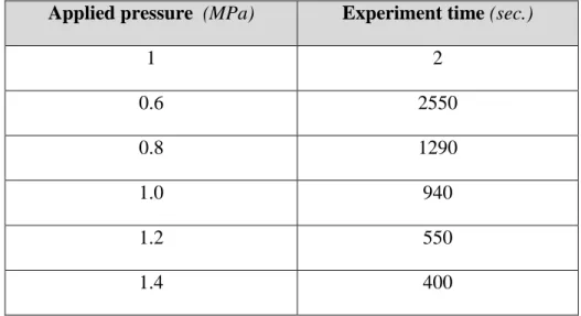
Table 4.1: Experiment results for application of constant gas pressure to the sheet…...48
Table 4.2: Material properties for Ti6Al4V (Vasin et al., 2003)………49
Table 4.3: Analysis results for different element sizes……….………...50
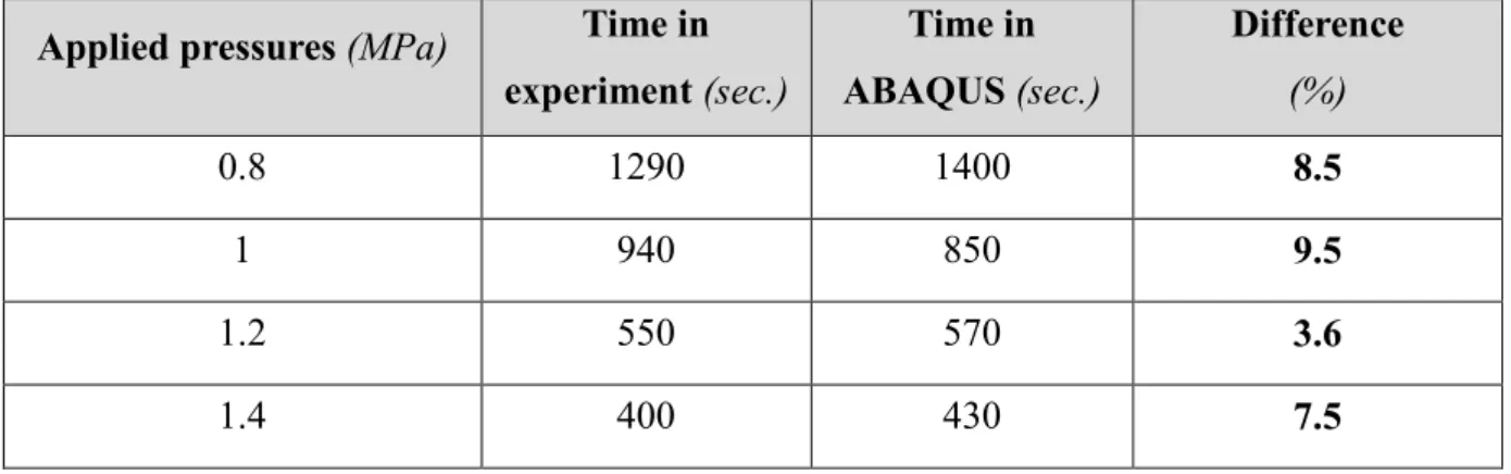
Table 4.4: Comparison of analysis time with experiments………51
Table 4.5: Comparison of analysis results with experiments……….…………51
Table 4.6: Comparison of analysis results with experimental data for different target strain rates………..54
Table 4.7: Experimentally determined power law creep properties (Warren and Wadley, n.d.)………...………….57
Table 4.8: Analysis results for different element sizes………...58
Table 4.9: Summary of results obtained for process temperatures of 840 and 900 degree ……...………63
Table 4.10: Summary of the results obtained for different target strain rates………….66
Table 4.11: Summary of the results obtained for different sheet thicknesses………….68
Table 4.12: Comparison of results obtained of different friction coefficients at different target strain rates………72
Table 4.13: Comparison of final thicknesses for different die entry radii …...………..75
Table 4.14: Geometric properties of conical die for different analyses………..83
Table 4.15: Geometrical properties of test specimen……….84
Table 4.16: Results for different die entry radii………...……..84
Table 4.17: Geometric properties of conical die for different AR values………...87
Table 4.18: Results summary for different aspect ratio of the die………...87
Table 4.19: Comparison of results obtained of different friction coefficients at 10-3 target strain rates………89
Table 6.1: Process parameter alternatives for production of blowout door………....102 Table 6.2: Summary of obtained results for different process parameters…………...103 Table 7.1: Total cost calculation for FEA study (TEI, 2017)………...106 Table 7.2: Estimated cost calculation for experiments and comparison with FEA study (TEI, 2017)………...………...107
Formula Symbols and Abbreviations
Formula Symbols
Symbol Unit Description
ε° - Strain rate
- Strain
D - Diffusion coefficient
Cm - Dimensionless constant
G MPa Shear modulus
b μm Burgers vector
K J/K Boltzmann constant
T K Absolute temperature
d μm Average grain size
σ MPa Applied stress
q - Dimensionless exponent
m - Strain rate exponent
Do m²/s Independent coefficient of diffusion
Q kJ/ mol Activation energy of creep process
R J/ mol x K Gas constant
n - Strain hardening coefficient
Tdef K Deformation temperature
Tm K Melting temperature
L mm Element length
E MPa Young Modulus
ρ
kg/m3 Densityt
s Time step
ε
°opt - Target strain rate
- Ratio of equivalent strain rate to target strain rate
r+1 - Iteration number
Pr+1 MPa Applied pressure at iteration number r+1
Symbol Unit Description Y - Dependent variable X - Independent variable a - Intercept b - Slope of line e - Error terms β - Regression coefficients ʋ - Poison’s ratio µ - Friction coefficient
p MPa Critical frictional shear stress
h mm Height of the die
d1 mm Outer diameter of the die
d2 mm Inner diameter of the die
re mm Entry radius of the die
rf mm Root radius of the die
α - Inclined angle of the die
AR - Aspect ratio of conical die
T second Predicted process time
t mm Sheet thickness
Pi MPa Initial Pressure
L mm Sheet length
w mm Sheet width
hf mm Final dome height
Indices Indice Description def. Deformation sec. Second Max. Maximum Min. Minimum Eqv. Equivalent thick. Thickness
coeff. Coefficient
$ United States Dolar
Lub. Lubrication
Abbreviations
Abbreviation Description
SPF Superplastic Forming
TEI Tusas Engine Industries
TAI Turkish Aerospace Industry
GE General Electric FE Finite Element Al Aluminium Ti Titanium Cu Copper Mg Magnesium DB Diffusion Bonding
FSP Fine Structure Plasticity
ISP Internal Stress Plasticity
GBS Grain Boundary Sliding
DC Dislocation Creep
FLD Forming Limit Diagram
FEM Finite Element Method
FEA Finite Element Analysis
MIT Massachusetts Institute of Technology
CPU Central Processing Unit
LS Least Square
LMS Least Median of Squares
1 Introduction
High fuel cost builds the need for application of lightweight materials in automotive and aerospace industry. SPF is an alternative manufacturing method of light weight alloys for manufacturing complex shapes at high temperatures. (Shojaeefard et al., 2014) SPF process is a near-net shape process which is used to shape superplastic materials that can withstand to large tensile deformations. This process can generally be applied to Aluminium (Al) and Titanium (Ti) alloys at high temperatures and special conditions. SPF has ability to form complex shapes which are impossible with other conventional methods. Cold forming and hot forming processes used to be preferred in industrial applications for producing complex shaped geometries before SPF process is developed. In SPF process, the workpiece is clamped to the die and heated to SPF temperature, then inert gas pressure is applied to workpiece with a predetermined rate to get the shape of the die. This process enables parts to be elongated nearly 1000% and mechanical properties obtained are good with low flow stresses, furthermore, net shape geometries are achieved with SPF process. Surface finish obtained after SPF process is also sufficient and this emits surface finish operations after forming process as in the conventional methods. SPF process also permits to produce large parts and this can also eliminate assemblies and can also enable to reduce part weights. (Sieniawski and Motyka, 2007)
Compared to conventional methods for instance fabricating, SPF improves fatigue strength properties, so it increases cycles to the failure. Furthermore, SPF reduces metal consumption significantly, labour and machining costs are decreased with this process. Because lower pressures are applied to the specimen, lower power equipment are required, so manufacturing costs could also be decreased. (Ermachenko et al., 2011) Mentioned assets of SPF process make it very important in many industrial applications, especially in Aviation industry, since product quality and light weight is a very important criterion. SPF process plays an important role in Aviation industry since 30 years for its numerous advantages.
Besides than advantages of SPF process, it has disadvantages, too. SPF process is an expensive process according to conventional processes, since it requires very high process temperatures. Furthermore, it requires very small grain sizes which require expensive treatments to the material and low strain rates which make process to continue for a very long time. This makes this process incapable for mass production. (Marinho et al., 2012)
In selecting a process as a method to produce a part in industry, both technological and economic factors need to be considered. Although, mentioned advantages make the process very important in Aviation industry, since quality and lightweight are most important criteria, cost and time aspects also need to be considered.
Most important process parameters affecting SPF process are process temperature, pressure cycle, die radius, thickness of the sheet material, lubrication, material type and grain size of the material. The effect of various parameters to the SPF process could be investigated by finite element analysis in order to obtain an optimum process for economical and quality aspects.
1.1 Motivation and Objective of the Thesis
TEI is a joint venture company of Turkish Aerospace Industry (TAI), General Electric Aviation (GE) company, Turkish Armed Forces Foundation and Turkish Aeronautical Association and produces components for different Aerospace companies. The problem and topic for this thesis are defined by TEI.
TEI desires to add SPF process to its manufacturing capabilities, because it could succeed elongations until 1000%, also TEI aims to decrease weight of components by removing joints that are used in conventional processes such as cold, hot forming for assembly purpose, because SPF enables to produce complex parts in one step. Furthermore, increasing service lives and saving cost are another reasons for preferring this method as an alternative approach. In order to compete with other suppliers for aviation industry, TEI needs to include SPF to its current capabilities. Before adding SPF to current manufacturing capabilities, TEI desires to learn the process deeply.
The motivation for this thesis is to investigate effect of process parameters of SPF process for Ti6Al4V material with aid of finite element analysis (FEA) program. Since the experiments have high costs especially for Aviation industry materials, TEI desires to save cost by investigating process parameters with FEA instead of doing experiments for considerably expensive aviation materials.
The motivation could be succeeded by analysing of SPF process with the aid of a FE software ABAQUS for different process parameters. Process parameters are investigated for rectangular and conical parts for simplification, and ABAQUS creep module is used to simulate forming process, since the experiment capability is absent, current analysis approach is compared with experiment results obtained from literature. Process parameters are investigated by running several analyses with creating scripts in order to have an automated process. Furthermore, this study includes development of a tool for predicting forming time of SPF process for a rectangular box without doing several analyses by using machine learning and data mining techniques. Later, SPF of an aircraft blowout door for different process choices are investigated in order to find an optimum process to manufacture. Finally, a cost analysis study is conducted for this project in order to estimate the profit gain by conducting FEA study instead of realizing experiments.
1.2 Outline of the Thesis
There are eight chapters in this thesis work. The thesis structure is organized as explained below:
Chapter 1. Introduction
This chapter gives a general introduction and outline for the motivation and objective of the thesis.
Chapter 2. State of the Art
This chapter gives an overview about the theory of subjects such as metal forming, SPF, information about superplastic Ti alloys, FE formulation of SPF process and machine learning and data mining. The metal forming processes are divided in two groups as bulk and sheet metal forming, and they are briefly described whereas SPF process is explained in detail. Theory of SPF process and superplasticity are given, technological
and economical aspects of SPF process are explained and superplastic behaviour of Ti alloys are described. This chapter also contains information about FEA of SPF process in detail. Furthermore, machine learning and data mining techniques are briefly explained in this chapter.
Chapter 3. Aim and Scope of the Thesis Work
This chapter explains the aim and scope of the thesis work.
Chapter 4. Investigation of Process Parameters to SPF Process
This chapter includes comparison of FEA results of SPF process of a rectangular part with experimental results obtained from literature. Forming behaviour of SPF process is also investigated in detail in this chapter. Furthermore, this chapter contains investigation of process parameters for rectangular and conical parts for SPF process. Chapter 5. Development of an Equation for Estimation of Process Time for SPF Process by Machine Learning for a Rectangular Box
This chapter is dedicated to development of an equation to estimate process time of SPF process for a rectangular box.
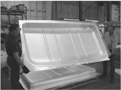
Chapter 6. Application of SPF Process for an Aircraft Blowout Door
In this chapter, SPF process application is presented for an aircraft blowout door, an optimum process is aimed to obtain from various process choices.
Chapter 7. Cost Analysis of SPF Process for the Factory
In this chapter, a cost analysis study is conducted in order to compare numerical analysis study cost with a possible experimental effort cost.
Chapter 8. Conclusion
This chapter includes final conclusions of the thesis work and recommendations for further studies.
2 State of the Art
2.1 Metal Forming
Forming is a process to obtain the desired shape and size from a raw material by exposure of the workpiece to plastic deformation by applying tensile, compressive, bending or shear force or combination of these forces. (Nptel, 2016)
Metal forming processes are defined as deformation processes, that metal billet or blanks are shaped by tools or dies. Processes of metal forming are controlled based on certain parameters such as material of workpiece, tool/work piece conditions, mechanics of plastic deformation named as metal flow, used equipment and requirements that expected from a finished product. These parameters affect selection of processing conditions such as operation temperature, lubrication between workpiece and tool, also choosing workpiece, tool geometry and materials. (ASM, 2016).
Metal forming processes are divided into two main groups; bulk and sheet metal forming as shown in Figure 2.1.
2.1.1 Bulk Metal Forming
Bulk metal forming starting material form is generally billet, rod or slab. Formed part surface to volume ratio increases, since part is applied to a large compressive loads. Processes which are categorized under bulk forming have following features;
Workpiece encounters very large and permanent plastic deformations, Workpiece has in the end significant change in shape or cross section
Plastic deformed portion of workpiece is mostly larger than elastic deformed region, so elastic recovery is not possible.
The portion of the workpiece undergoing plastic deformation is generally much larger than the portion undergoing elastic deformation; therefore, elastic recovery after deformation is negligible. Extrusion, forging, rolling and drawing are most common forming processes which can be categorized under bulk metal forming. (Altan et al., 1983, Altan et al., 2004) Main bulk forming processes are shown in Figure 2.2.
Figure 2.2: Basic bulk deformation processes: a) rolling, b) forging, c) extrusion, and d) drawing (Groover, 2012)
In bulk metal forming, deformation is three dimensional, this is the main feature which distinguishes bulk metal forming from sheet metal forming, because in sheet metal forming processes deformations are mostly in plane of sheet metal. (Forging, 2016) 2.1.2 Sheet Metal Forming
Sheet metal forming procedures consist of cutting and forming of relatively thin sheet metals. Sheet metal thicknesses are typically between 0.4-6 mm. Forming of sheet metals are generally carried out at room temperature. In sheet metal forming, only workpiece form changes, but workpiece cross section does not change. Forming is accomplished with a punch and die. Sheet metal forming is mostly divided to two main categories, one of them is cold forming in which forming is carried at room temperature, second one is named as hot forming, in which material is heated to a temperature higher than melting temperature of the workpiece. Sheet metal forming has a very significant commercial role, since number of consumer and industrial products of sheet metal formed parts consist of automobiles, airplanes, railway cars, office, furniture, home appliances. Sheet metal parts have generally good dimensional accuracy, good surface finish, high strength and low cost relatively. Basic sheet metal forming processes are shown Figure 2.3.
Figure 2.3: Basic sheet metal working operations: a) bending, b) drawing, c) shearing: 1) as punch first contacts sheet, and 2) after cutting (Groover, 2012)
2.2 Superplastic Forming
SPF process is a sheet metal forming process which is capable of withstanding large uniform elongation before necking. High fuel cost is driving the need for using lightweight materials in automotive and aerospace industry, this can be realized by replacing steel with light weight alloys. SPF is an alternative manufacturing method of light weight alloys for forming complex shapes at high temperatures by usage of gas pressure. Superplastic materials have ability to withstand to elongations nearly 1000% at elevated temperatures and low strain rates. (Shojaeefard et al., 2014)
Since today, many researches have been conducted for superplasticity and SPF, they were crucial to establish the limits to the utilize of SPF process. In 1934, Pearson succeed 1950% elongation in Bi-Sn alloy. (Marinho et al., 2012)
Figure 2.4: Bi-Sn alloy (1950% elongation) (Marinho et al., 2012)
Since 1964, main research focus was to find out maximum stretching by hot uniaxial tests, technological researches started after study of Backofen, they begun to investigate strain rate sensivity exponent in more details. Backofen, Turner & Avery, in 1964, from the Massachusetts Institute of Technology (MIT), they published their well-known paper which is sheet of Superplastic AlZn eutectoid alloy was pneumatically formed as a bubble. Their research put the necessity of new technology, SPF.
Prof. Backofen and his research group authorized importance of strain rate sensitivity index as the neck-free tensile elongation characteristic of superplastic materials at MIT. Furthermore, they also researched Ti, Copper (Cu) and Magnesium (Mg) alloys.
While Backofen established his study in 1964, Dr. Field found out that extraordinary formability is possible with superplastic materials by working Backofen’s study. Later in 1965, Dr. Field did first SPF patent application with usage of sheet-tube forming for thermoforming plastics.
The first laboratory for investigation of SPF is ‘Electricity Council Research Center, Capenhurst’, and first conference about SPF was done here in 1969.
In 1971, the first commercial SPF company in the world was founded as ISC Alloys Ltd., Avonmouth Bristol, United Kingdom, the aim of this company was to produce complex-shaped components using ZnAl eutectoid alloy with low-cost tooling and forming times.
After 1969, much progress was achieved to scale up special process requirements to achieve feasible production. Then, largest uniform elongation which is nearly 8000% is obtained with commercial bronze. (Marinho et al., 2012) This is clearly illustrated in Figure 2.5.
Figure 2.5: Development of SPF maximum elongation through years (Marinho et al., 2012)
At the beginning of 1970s, developments initiated also in Aerospace industry, first one was the SPF of Ti alloy and combination of SPF and diffusion bonding (DB), this attempts are done with help of government funding. First commercial application of SPF was a jack housing with SPF of a Ti alloy by British Aerospace Filton for A310 Airbus aircrafts.
In 1980s, SPF of Ti alloys broadened, and 10 years later, an aerospace contractor company Rohr Industries had produced more than 400 different parts with SPF process. In these days, there have been many innovations with superplasticity to achieve controlled process which means all of the variables (temperature, strain rate, position…) of SPF process need to be controlled to have an optimum forming process. (Marinho et al., 2012)
SPF technology has been developed in recent years, in the past, sheet was heated, clamped to the die and stretched to the tool surface, a formed part for large one-piece truck cab roof in SP5083 alloy can be seen in Figure 2.6, but nowadays non-planar clamp line tooling arrangement is utilized. Press is closed after loading and heating, then it is bent drawn to conform with shaped clamp line. With this method, more unstrained material enters the tool and less strain is generated into the preformed sheet since it is formed pneumatically. This technique permits to obtain parts more quickly with less strain and more uniform thickness distribution. (Barnes, 2007)
Figure 2.6: Simple female forming example for large one-piece truck cab roof in SP5083 alloy (Barnes, 2007)
Superplastic materials have high flow stress sensitivity to strain rate, so this process is achieved at very low strain rates. SPF process has very advantageous features comparing to conventional forming processes, SPF has ability of near net shaping, producing multiple parts in one stage, just a little spring back and less tooling cost prices are main
advantages of SPF processes, but SPF process can be achieved in a more time, because high forming ability is realized at low strain rates, this handicap of SPF is main topic of many scientists to develop an optimum process for SPF. SPF is a valuable process to fabricate complex parts used in the aircraft and automobile industries and some of materials showing superplastic behaviour are listed below;
Titanium (Ti6Al-V)
Aluminum (2004, 2419, 7475) Zinc-Aluminum
Bismuth-Tin
Aluminum-Lithium alloys (2090, 2091, 8090) (Shojaeefard et al., 2014) 2.2.1 Theory of Superplasticity
Superplasticity is capability of polycrystalline materials to perform high strains at a high temperature under low stresses which is dependent on strain rate. Tensile elongation of superplastic materials can be more than 2000%. There are two types of superplasticity; fine structure plasticity (FSP) and internal stress superplasticity (ISP). FSP can be defined as internal structural aspect of materials, while ISS is occurred by external conditions such as thermal or pressure cycling, and they cause internal structural deformations which concludes high internal stress independent from external stresses. (Sieniawski and Motyka, 2007)
Under low strain ranges and temperatures above 0.4Tm, in fine-grained isotropic metallic materials FSP occurs. High strain rate sensitivity parameter (m >0.3), conversion of texture while deformation, low lattice dislocation activity in grains, severe grain boundary sliding (GBS), lack of strain hardening are crucial aspects of superplastic deformation. (Grabski, 1973, Mukherjee 2002)
Experiments on microstructural processes prove that there exists cooperative grain-boundary sliding related to sliding of groups of grains. Figure 2.7 shows GBS during a superplastic deformation on metallic materials.
Figure 2.7: GBS while superplastic deformation (Sieniawski and Motyka, 2007) Most effective group of superplastic materials are two-phase alloys which are Al6Cu0.4Zr, Ti6Al4V, Ni9Si3.1V2Mo, since one of the phases provides grain size stability and at a deformation temperature material is undoubtly less sensitive to grain growth. (Sieniawski and Motyka, 2007)
The mechanism controlling behaviour of high temperature plastic deformation in polycrystalline materials is expressed with Equation (2.1).
1 ( ) (q ) m m C DGb b KT d G (2.1) Here; : strain rate; D: diffusion coefficient;
Cm: Dimensionless constant [-], incorporating all structural parameters except grain size; G: Shear modulus [N/mm²], [MPa];
b: Burgers vector [μm];
K: Boltzmann constant [1,381 x 10-23 J/K]; T: Absolute temperature [K];
d: Average grain size [μm];
σ: Applied stress [N/mm²], [MPa]; q: Dimensionless exponent [-]; m: Strain rate exponent [-].
This equation is developed by Mukherjee-Bird-Dorn, and it is being used more than 30 years and shows good results for metal alloys which have been used for over three decades, showing good results with materials such as metal alloys. The diffusion exponent of equation is also calculated as below;
0
Q RT
d D (2.2) D0: Independent coefficient of diffusion [m²/s];
Q: Activation energy of creep process [kJ/ mol]; R: Gas constant, 8.314 [J/ mol x K];
: Strain.
If Equation 2.1 is substituted to 2.2 Equation (2.3) is obtained; 1 0 ( ) (q ) Qc RT m m C D Gb b KT d G (2.3)
Equation (2.3) is rewritten to relate the flow stress (σe), the strain rate (ε°) and strain (ε); in its new form, it is called a Norton-Hoff power law equation and expressed as below;
. n m
e K
(2.4)
K: Material constant (Boltzman constant); m: Strain rate exponent;
n: Strain hardening coefficient. (Marinho et al., 2012)
In high temperature plastic region, effect of n is known very small and m has dominant effect to the equation, so Equation (2.4) can be simplified to equation below;
. m
e K
(2.5) where σ is named as the flow stress. (Marinho et al., 2012)
Figure 2.8: A typical stress strain rate diagram with change of strain rate sensitivity (Deshmukh, 2003)
Superplastic behaviour of materials can only happen in region II, because strain rate sensitivity has highest values at that region. For most of the superplastic materials m lies in region of 0.4 to 0.8. If there exists necking in a material as a results of tensile straining, it causes locally high strain rates and if there are high values of m, there will be sudden increase in flow stress in necked region. As a result, necking experiences strain rate hardening which obstructs its development further, hence high strain rate sensitivity causes resistance to development of necking and brings about high tensile elongations behaviour of superplastic materials.
There is not only one mechanism to define deformation in region II, and this region is not still explained well, but GBS is accepted to be the main mechanism accompanied by diffusion, dislocation climb and glide. Region III is controlled by dislocation creep (DC) (power-law creep). In this region, deformation caused slip lines and high dislocation densities are observed, furthermore high grain elongations and crystallographic texture occur. (Deshmukh, 2003)
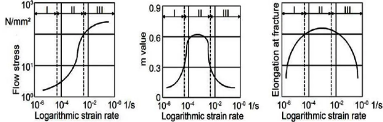
Figure 2.9: Relation between flow stress, elongation at fracture and m with strain rate (Marinho et al., 2012)
Figure 2.9 illustrates relations between m values, logarithmic strain rate and rupture elongation. Logarithmic strain rate is very important in region II, in this zone elongation at rupture and value of m has their maximum in that region. Region I is insensitive, because both m and rupture elongations are minimum here, same behaviour could be seen in region III, also. As a result, SPF happens only in region II. Table 2.1 summarizes microstructure changes in three regions.
Table 2.1: Summary of change in microstructure in the three regions (Marinho et al., 2012)
Region I Region II Region III
Flow stress does not depend on strain rate, low m values are seen, small deformations
only
High m values occur, strain rate has important effect on
flow stress, large deformations can occur
Flow stress does not dependent on strain rate, low m values are seen, small deformations only
Limited elongation of individual grains
Nearly no elongations of individual grains occur, grains move together, only small changes of neighbour
grains
Limited elongation of individual grains
It should be considered that there is not only one model to express mechanical and metallurgical features in SPF. Sometimes, it is not possible to obtain same results from mechanical tests as in the SPF process. (Marinho et al., 2012)
2.2.2 Superplastic Blow Forming
SPF is a pressurized forming method that has ability to manufacture complex shapes from superplastic alloys and is also named as superplastic blow forming. Figure 2.10 shows steps of superplastic blow forming processes, as seen in the figure, to form the sheet, a die cavity and gas pressure is required, sheet is clamped to the die and pressure of the gas is applied to it.
Figure 2.10: Steps of superplastic blow forming process (N.N., 2008)
In order to realize forming process, an inert atmosphere is required, argon gas is generally used for pressurization, and argon gas also saves inert atmosphere to maintain forming process. Profile of pressure versus time needs to be determined prior to process, because controlled rate of deformation is required. At the beginning of process, workpiece is not in contact with the die, deformation happens at the pole of the sheet. As a result of that, high deformation strains occur at that region during initial stages, later specimen has contact with the die, and corners are filled at the end of the forming process. Corners have greatest strains, so these regions can fail easier compared to other regions of the sheet metal. (Deshmukh, 2003)
2.2.3 Superplastic Forming Process Parameters
Although SPF process has many advantages which are mentioned in Chapter 2.2, forming process is expensive with this method, because temperatures of forming are very high (process temperature has to be nearly %60 of melting temperature), furthermore strain rate should be less than 10-2 s-1 and grain size of the specimen needs
to be less than 10 µm. Small grain size materials are not unfortunately cost effective, since they require expensive processes to be obtained. Low strain rates make the process long and not suitable for mass production. It is important to consider both economic and technological aspects of SPF technology before deciding to produce a part with SPF method. (Cappetti et al., 2010)
Many investigations have been done by researchers since now to optimize process of SPF, for instance the effects of temperature and forming speed on the forming limit diagram by Naka and others. (Naka et al., 2001)
Furthermore, Luckey and others achieved simulation of improvement of SPF process with thickness profile. (Luckey et al., 2009)
2.2.3.1 Temperature
Deformation temperature 𝑇𝑑𝑒𝑓 should be greater than the half of the absolute melting temperature 𝑇𝑚 , for the occurrence of superplasticity.
𝑇𝑑𝑒𝑓 >1
2𝑇𝑚 (2.6)
Depending on the used material, temperature value activating and balancing GBS and DC changes. High working temperature increases contribution of GBS to final elongation and reduces strain hardening. Although high temperature improves mechanical characteristics of product, it causes molecular phenomenon like rising grain
size. Moreover, high forming temperature decreases life time of die and presses because of higher stresses. Therefore, better mechanical presses with improved mechanical properties but with high costs are required. (Cappetti et al., 2010)
2.2.3.2 Pressure Cycle
During SPF, contact areas between sheet and die increase and strain rate reduces. To have constant strain rate, pressure during process must increase with time. Control of strain rate is very significant since it affects three flow phenomenon and Backofen sensitivity coefficient m. With increasing strain rate, strain hardening rises and it causes worse mechanical properties of product. With fixed temperature, 𝑚 value increases at first up to a maximum strain rate value then it decreases. (Cappetti et al., 2010)
2.2.3.3 Die
One of the most important parameter is the radius of the die since it affects the thinning and breaks. For instance, small radius at the top of the die prevents material flow towards the center of blank and increases global thinning. Furthermore, complex and very deep dies also obstruct material flow. (Cappetti et al., 2010)
2.2.3.4 Lubrication
Lubrication helps sliding between blank and die and it influences thinning of blank. It has a direct influence on friction force level during process. High friction coefficient causes high friction forces which results non-homogeneous thickness distribution. Therefore, in SPF processes it is important to reduce friction coefficient by utilizing lubrication. (Cappetti et al., 2010)
2.2.3.5 Grain Size
Superplastic materials ought to have equiaxial and fine grained structure, it is known that grain refined materials have higher strain rates and they require less forming temperature. Figure 2.11 shows how strain rate is increasing for small grain sizes, and Figure 2.12 illustrates forming temperature decreases for small grain sizes. (Sieniawski and Motyka, 2007)
Figure 2.11: Effect of grain size to strain rate (Sieniawski and Motyka, 2007)
.
Figure 2.12: Effect of grain size to working temperature (Sieniawski and Motyka, 2007)
When evaluating aspects of SPF process, some features need to be considered such as distribution of thickness, maximum thinning, forming time, required pressure, occurring stresses and cost of manufacturing. Maximum thinning and distribution of thickness are related to mechanical features of product which are stiffness, strength, they also determine quality of the product from customer side. Forming time is mostly related to
feasibility of the process, since if it has such a long time it can be unacceptable. (Cappetti et al., 2010)
2.2.4 Technological and Economical Aspects of SPF Process
In a superplastically formed part, hardening of material does not exist and spring-back is zero, furthermore neck free and very large elongations are possible with SPF process. SPF process enables to produce very complex parts in one step, this removes many assembly processes, joints thus decrease part weights. These properties of product make it a very good finished product which has high dimensional accuracy that obstructs extra finishing treatments. Furthermore, it reduces metal consumption from 2-5, labour of machining is also decreased with this process, it also enables to reduce manufacturing costs because lower power equipment can be used and their service costs are less compared to other processes. SPF process is being used in aerospace and automotive industry, medicine and ship building where material savings are very crucial. Especially product quality, weight reduction, service lives are very important for aerospace industry since product costs are high and quality of product is very important for safety requirements. (Ermachenko et al., 2011)
Low flow stresses and large elongations during SPF process make it to be used as a manufacturing process like thermoforming of plastics. (Ceschini and Afrikantov, 1992) SPF is expensive, because process temperature is high which is more than 60% of material melting temperature, grain size in average should be less than 10 µm, and strain rate required is very small. (less than 10-2 1/sec.). Small grain size requires very expensive material treatments; furthermore, different heat treatments can be required to advance material mechanical properties. SPF is being used in aerospace industry for more than 30 years for production of such as blades, discs of gas turbine, cylinders and flanges. For example, fan blades are used to be manufactured with conventional method fabricating. Fabricating of fan blades required labour-intensive mechanical working and utilization of metal was very low. Furthermore, deformation of part is very high and hot blank faces into contact with cold die which causes plasticity to decrease and local zones with different properties are created. These handicaps of conventional process lead to manufacture fan blades with SPF process. (Ceschini and Afrikantov, 1992)
Figure 2.13: Fatigue curve comparison for fan blades for SPF (1) and conventional (2) methods (Afrikantov, 1992)
Comparison of fatigue strength versus cycles to failure diagram for both methods is illustrated in Figure 2.13 and it proves that SPF process significantly improves fatigue strength properties compared to conventional method. Furthermore, it creates more near-net shape product under superplastic conditions. (Afrikantov, 1992)
Forming limit diagram (FLD) for materials are defined with a curve of major strain versus minor strain, FLD expresses the boundary within elastic or plastic deformation, failure possibility is expressed by the distance between actual strain condition in the forming process and the forming limit curve. Usage of SPF process is restricted by slow strain rates, this is elemental feature of the process and needs to be localized to the area which has forming risk, here strain needs to be small which makes process time long. Although SPF process has excellent features which make it very advantageous over conventional forming processes, handicaps mentioned above need to be considered before deciding to use this method for production of a part, both technological and economic factors should be considered. (Marinho et al., 2012)
When selecting a process and material for manufacturing purpose main considerations are minimum cost and maximum structural efficiency. Weight and cost savings drive to select SPF for manufacturing process.
2.3 Information about Superplastic Titanium Alloys
Ti alloys are one of the most important materials in high strength materials, especially in aerospace industry. Mostly, aircrafts are manufactured by Al alloys, for the high temperature exposure and unyielding strength necessary places Ti alloys are preferred. Al has lower density compared to Ti alloy, but Al alloys do not have high strengths at elevated temperatures. Furthermore, Ti alloys have also corrosion free features while Al not. Cost of a Ti alloy is nearly 8 times more expensive than an Al alloy. In these days, it is really significant in aerospace industry to have advancement in technology from design, production sides. SPF is an advanced technology that supplies reductions in both procurement and life cycle costs. (Sieniawski and Motyka, 2007)
In this section, SPF characteristics of Ti alloys will be investigated, since they are irreplaceable materials of aerospace industry.
Superplastic alloys are mostly two-phase alloys such as Al6Cu0.4Zr, Ti6Al4V, Ni9Si3.1V2Mo, since grain size stability is provided by one phase, as a result material becomes less prone to grain growth. Ti and Ti matrix composites are generally interest by manufacturers and researchers. Especially, Ti6Al4V alloy is utilized and investigated in recent years. At 70’s years, ultimate tensile elongation of this alloy was approximately 1000% at 10-4 1/sec. strain rate, but it has been improved by the recent develops. For
instance, applied thermomechanical methods doubled tensile elongation and increased strain rates nearly 100 times. TiAl or Ti3Al are intermetallic alloys which are relatively new group in superplastic Ti alloys. Intermetallic based alloys are known with their high temperature creep resistance and high relative strength. (Sieniawski and Motyka, 2007) As seen from Figure 2.14, extremely high elongations are possible with Ti6Al4V compared to other commercial superplastic alloys.
Figure 2.14: Strain rate sensivity diagram of superplastic materials (Ghosh and Hamilton, 1986)
Optimum conditions for Ti6Al4V is at a temperature between 870°C and 927°C and 4-8 µm grain size. Strain rate intensity is investigated by many researchers and values in the range of 0.5-0.8 showed increased elongations. (Miller et al., 1979)
2.4 Finite Element Formulation of SPF Process
FEM is a numerical procedure to analyse many problems which are mostly very complicated to be able to be solved by classical analytical methods, and FEA is a very useful method to solve engineering problems. (Deshmukh, 2003)
Since the early one dimensional membrane analysis of Ghosh and Hamilton (Ghosh and Hamilton, 1986), many innovations have been done to obtain more realistic nonlinear finite element models of SPF process. It is now achievable to get more accurate thickness predictions of complex 3d shapes and gas pressure profiles which can be later directly applied to gas management systems. Furthermore, it is possible to visualize sheet movement while the whole forming process. It is also possible to see wrinkles and study on how to obstruct them, then it is possible to develop real tool with the desired properties. By the usage of commercially developed software and powerful computers,
in just a few central processing unit (CPU) hours, it could be possible to validate tool design and optimization of process parameters. It has still challenges to have a successful SPF modelling which can be summarized as;
Selecting explicit or implicit analysis codes
Having sensible constitutive equations for interested materials Reliable modelling of tool and dies (Marinho et al., 2012)
In order to simulate a forming process by finite elements method, first model of the sheet-die assembly is created, according to problem, 2D, 3D, axisymmetric or symmetric models can be created. Best model should be decided according to computational costs, then model is divided by finite elements by choosing convenient element type and appropriate element size. Choosing the material model is one of the most important steps of forming analysis, because it specifies the strain and stress behaviour of the parts during analysis. Finally, boundary conditions and loads are applied to the model, here loads simulate the releasing the plunger to the clamped sheet. It is possible to model irregular shaped structures, handle various boundary conditions, process parameters easily and cheaply compared to testing in a real condition. Advantages of FEM make it an ideal tool to analyse SPF processes. (Deshmukh, 2003) Most of the researches of SPF has been done since now is to develop an optimum pressure algorithm in order to reduce forming time and to obtain uniform thickness distribution.
2.4.1 Implicit and Explicit Approaches
Explicit and implicit methods are approaches used in numerical analysis for obtaining numerical solutions of time-dependent ordinary and partial differential equations, as is required in computer simulations of physical processes. Metal forming processes are classified as quasi-static or high strain rate phenomena. In a quasi-static problem, kinetic energy is an unimportant part of total energy, SPF is in this category, while in high strain rate problems kinetic energy constructs an important role and they are generally dynamic processes.
Implicit approach is a method that gives full static solution of the deformation with control of convergence, this method enables large time increments, but when contact occurs, it obstructs high time increments. Computation time can increase 4 times with increase in elements. Also, at bifurcation points (for instance at beginning of wrinkling) there is singularities in the stiffness matrix. Central time differentiation scheme is utilized by dynamic explicit method, and time step is calculated by Equation (2.7).
L E
t
(2.7)
Here, L is the length of the element, E is the Young’s Modulus and ρ is the density. For a SPF analysis, a time step is very small and this causes high number of time steps, this makes this method disadvantageous for SPF analysis. Increasing density of material is a method to decrease the required number of time step. (Deshmukh, 2003)
Both method can be successful in SPF analysis, hence implicit method is a better choice for SPF from time perspective and enables full static solution of problem with control of convergence, so implicit method is preferred in this study.
2.4.2 Finite Element Analysis of SPF Process in ABAQUS Software
In this study, commercial finite element solver ABAQUS 6.13.1 which is a FE code includes direct implicit integration time integration by Hilber-Hughes operator is used. This program is selected generally for SPF processes, because it permits a full static solution of deformation problems with a convergence check. Furthermore, time increment size could be arranged practically. However, in an explicit analysis method, stability criterion makes the time steps very small and it can require thousands of time steps. Quasi-static implicit method is a better choice than explicit dynamic method for a SPF process. (Nazzal and Khraisheh, 2005)
SPF process is a complex forming procedure that has large strain, deformation, nonlinearity of materials and boundary conditions generally depend on material nonlinearity. As a result, numerical analysis of such a complex and nonlinear problem is really difficult. However, SPF can be expressed by flow stress which is a function of strain rate, this permits the material to be described as rigid viscoplastic. Consequently,
FE analysis of SPF process can be achieved using the creep strain rate control scheme within ABAQUS.
Constitutive behaviour of the specimen is very crucial to predict thickness distribution behaviour accurately during the forming process. In this study, material behaviour is expressed by the Equation (2.8).
. m
e K
(2.8) Here, is flow stress and ε° is the strain rate, K is material constant and m is strain rate sensitivity index. In the FE analysis, this equation can be implemented by usage of creep material model in ABAQUS. (Chen et al., 2001)
2.4.3 Modelling of SPF Process in ABAQUS Software
SPF can require modelling of very complex components, so it is very important to model shape of die surface accurately and generate an adequate mesh quality. It is possible to use advantage of symmetry, which can be reflective, skew, axial or cyclic. Here, symmetry means having symmetry in geometry, material properties and boundary conditions. Modelling assemblies partially is very advantageous, it decreases solution time. In a SPF analysis, more than quarter of the die needs to be modelled, because it is crucial to avoid points fall off the die surface during course of the analysis, and it obstructs contacting nodes to slide off over master surface. Die geometry can be meshed with three dimensional rigid elements, for a good convergence it is necessary to create rigid surface representation. Rigid elements are defined with R3D3 triangular elements, and ABAQUS automatically smooths any discontinuous surface normal transitions between the surface facets. (Nazzal and Khraisheh, 2005)
Mesh of the sheet is the main concern when doing FE analysis of SPF process. Sheet can be meshed with a membrane element or a shell element. In this analysis membrane element is preferred, because it is efficient from computing time and contact behaviour is handled easier. Membrane elements are type of surface elements and they only transmit in plane forces and they do not transmit moments, they don’t have bending stiffness. In SPF, bending effect could be ignored because thickness of sheet is very small regarding to other dimensions. Membrane elements have 3 degrees of freedom.
In a nonlinear analysis, cross section of the sheet changes with time. As seen in Figure 2.15, positive normal direction of a membrane element is expressed by right hand rule, and top surface of the membrane element is named SPOs face for contact definition and bottom surface is called as SNEG face for contact definition. (Hibbit and Hibbit, 2001, Deshmukh, 2003)
Figure 2.15: Positive normals for general membranes (Hibbit and Hibbit,2001)
In this study, M3D4 element typed membrane elements are used which are fully integrated bilinear membrane elements. In a SPF analysis, very large displacements occur and this can lead to buckling of sheet material when it is subjected to compressive loads. This condition can be handled by application of a small biaxial initial stress, the value of that stress should be in a value that final solution is not affected.
After meshing of the die and sheet metal part, another concern is definition of the contact behaviour between them. Contact problem in a SPF process is little complicated because sheet is not in contact with die at early stages and which parts are in contact in any stage is not clear, as a result contact is nonlinear because of asymmetry. A node could be in contact or rigidly constrained. In SPF analysis, classical ABAQUS coulomb friction model could be used, two surfaces are defined as contact pair which can have contact, there is master and slave surfaces. Node of the slave surface tries to find the closest node on master surface during analysis. In SPF analysis, rigid surface needs to be defined as master surface and deformable body should be defined as slave surface.
Figure 2.16: Coulomb friction in ABAQUS (Deshmukh, 2003)
Loading and controlling of the load is very important while realizing a SPF analysis. Controlling process parameters is one of the main difficulties of such an analysis. Temperatures and strain rates of the work piece should be in certain range that superplastic deformation can continue. Process should be realized as soon as possible and strain rates should not be more than maximum allowable strain rates at any location of the sheet. For this concern, ABAQUS has a component which helps to control loading with a solution dependent amplitude and a target maximum creep strain rate. This is activated by using the creep module of ABAQUS while material properties definition. When preparation of the analysis, user should define the reference value. When defining the amplitude, user should give initial, minimum and a maximum load multiplier. During the quasi static analysis, ABAQUS compares the maximum creep strain rate with target value, and load application is done based on this comparison. (Hibbit, 2001) Solution dependent amplitude pressure varies while simulation to maintain strain rate at a target strain rate. While any increment, ABAQUS calculates ratio of maximum equivalent strain rate to the target strain rate (ε°opt) which is specified by user. For any integration point for a specified element set. (see Equation (2.9).)
max opt
(2.9a) At an increment n, the pressure algorithm is progressed as below;
If max0.2 then Pr 1 2.0Pr (2.10a) If max3 then Pr 1 0.5Pr (2.10b) If 0.2max0.5 then Pr 1 1.5Pr (2.10c)
If 0.5max0.8then Pr 1 1.2Pr (2.10d) If 0.8max1.5 then Pr 1 Pr (2.10e) If 1.5 max3then Pr 1 0.5Pr (2.10f) Here, Pr+1 is the new calculated pressure to be applied at iteration number r+1, while P is applied pressure value of previous iteration whose number is r. Calculated pressure is applied to the free forming region of the sheet at each increment and clamped region is constrained from all degrees of freedom. (Hibbit, 2001)
SPF analysis in ABAQUS could be realized in two steps, first step is considered as elastic, the pressure is applied in a very short time and so the response is purely elastic. At second step, creep response is developed by usage of quasi-static procedure. During quasi-static step, an accuracy tolerance is specified and this controls the time increment so accuracy of the creep solution. When comparing the creep strain rate at the beginning and end of an increment, ABAQUS considers the difference and it should not be more than the tolerance divided to time increment. If it is higher, this step is repeated with a smaller time increment. Specification of this tolerance value is important, since it affects the stress and strain results. Lower tolerances end with good analysis results close to real values but they require more computation efforts. (Nazzal et al, 2004)
SPF analysis by using creep module in ABAQUS could be realized by using the creep definition available in ABAQUS, by application of time hardening power law. Time hardening power law is defined as the formula below;
. m e K (2.8) n C (2.11)
Here, n is creep stress exponent and C is the power law multiplies, n and C should be from an experimentally determined study. (Deshmukh, 2003, Hibbit, 2001)
2.5 Machine Learning and Data Mining
High performance computing and developments in information technology which are used in engineering simulations lead to having large data sets. Increasing data set is due to analysing them manually, hence there is information hidden in the available large data
sets and they are generally cannot be discovered manually, at this point, data mining techniques are required. (Twin, 2016)
Data mining is a sub-branch of computer science and utilized to find out patterns in huge data sets by using methods such as machine learning, statistics, artificial intelligence and database systems. Data mining in overall desires to get information from available data sets and create a structure which could be used in future. Data mining techniques are significant in design processes for engineering like structural, thermal flow design problems. When discovered problem gets more complicated, parameters and obtained data sets become huge and difficult to overcome. (Twin, 2016)
Figure 2.17: Illustration of data mining process cycle (N.N., 2016)
Figure 2.17 illustrates the data mining process cycle, it firstly started with business understanding which requires understanding objective of business and finding the needs. Later, data understanding starts in which initial data collection is done to be familiar with data, here data is explored, visualized and understood, and users ask themselves if the data has enough quality and required data collection is complete. Then, data preparation phase initiates which is the most time consuming phase of the data mining process. User needs to explore all available data set, if they make sense, if some of them should be cleaned or new data should be added. Later, they are formed into desired form according to which result is aimed to obtain. After data preparation phase, modelling