« я ^ 6 - е
У -. і Г ' . . r - L T r . ·
CONGESTION CONTROL IN
INTERCONNECTED COMPUTER NETWORKS
A THESIS
SUBMITTED TO THE DEPARTMENT OF COMPUTER
ENGINEERING AND
INFORMATION SCIENCES
AND THE INSTITUTE OF ENGINEERING AND SCIENCES
OF BILKENT UNIVERSITY
IN PARTIAL FULFILLMENT OF THE REQUIREMENTS
FOR THE DEGREE OF
MASTER OF SCIENCE
By
Özgür Ulusoy
June 1988
Q A Я Ь Л -D S
I certify that I have read this thesis and that in my opinion it is fully adequate, in scope and in quality, as a thesis for the degree of Master of Science.
/ (/ {·
Prof.Dr.Mehmet Baray(Principal Advisor)
I certify that I have read this thesis and that in my opinion it is fully adequate, in scope and in quality, as a thesis for the degree of Master of Scien^.
j^of.Dr.Efol Arkun
I certify that I have read this thesis and that in my opinion it is fully adequate, in scope and in quality, as a thesis for the degree of Master of Science.
Assist.Prof.Dr.Erded Arikan
Approved for the Institute of Engineering and Sciences:
ABSTRACT
CONGESTION CONTROL IN INTERCONNECTED
COMPUTER NETWORKS
Özgür Ulusoy
M.S. in Computer Engineering and
Information Sciences
Supervisor: Prof.Dr.Mehmet Baray
June 1988
A computer network has a collection of resources shared by multiple users. The capacity of the resources is limited, and if the user demands exceed the capacity, the network becomes ’congested’. The congestion causes a degrada tion in system performance. In interconnected networks there are two classes of traffic within a network. One class is the local traffic that is generated and transmitted within the network. The other class is the internetwork traffic transmitted to or from other networks. In this thesis, the effect of inter network traffic on the performance of a network is investigated. Computer simulation of an interconnected network model is provided in order to eval uate the effectiveness of a window-based congestion control mechanism on preventing congestion in gateways and in attached networks caused by the overload of internetwork traffic. Also two dynamic window congestion con trol algorithms are provided and studied. These algorithms provide further control to window mechanism by adjusting the window size in accordance with the availability of the network resources at the destination. Dynamic algorithms are evaluated comparing them with static window control.
Ke}’'words; Congestion Control, Computer Networks, Interconnected Com puter Networks, Window Control, Performance Evaluation.
ÖZET
BİLGİSAYAR AĞLARINDA AŞIRI YÜK KONTROLÜ
Özgür Ulusoy
Bilgisayar Mühendisliği ve Enformatik Bilimleri Yüksek Lisans
Tez Yöneticisi: Prof.Dr.Mehmet Baray
Haziran 1988
Bilgisayar ağları çok sayıda kullanıcı tarafından paylaşılan kaynakları içer mektedir. Bu kaynakların kapasitesi sınırlıdır ve kullanıcı istekleri bu kap asiteyi aşarsa, bilgisayar ağlarında aşırı bir yüklenme görülür. Aşırı yüklenme sistem performansının düşmesine sebep olur. Diğer bilgisayar ağlarıyla bağlan tısı olan bir ağda iki grup mesaj trafiği görülür. İlk grup ağ içinde üretilen ve transfer edilen mesajlardan oluşur. Diğer grubu ise başka ağlara trans fer edilen veya başka ağlardan gelen mesajlar oluşturmaktadır. Bu tezde ikinci grup trafiğin bir ağın performansı üzerindeki etkisi İncelenmektedir. Geliştirilen bir model üzerinde birbirine bağlı bilgisayar ağlarında ve geçitlerde görülen aşırı yüklenmenin önlenmesinde pencere metodunun etkinliği bilgisa yar benzetimiyle İncelenmektedir. Ayrıca pencere büyüklüğünün dinamik olarak değişebildiği bazı algoritmalar önerilmektedir. Bu algoritmalar pencere büyüklüğünün çeşitli ağ kaynaklarının o andaki yüküne bağlı olarak değişebil mesini sağlayarak pencere metodunun aşırı yüklenme problemine daha etkin bir çözüm getirmesini sağlamaktadır. Dinamik algoritmalar, statik pencere kontrol metodu ile karşılaştırılmalı olarak İncelenmektedir.
Anahtar Kelimeler: Aşırı Yük Kontrolü, Bilgisayar Ağları, Birbirine Bağlı Bilgisayar Ağları, Pencere Kontrolü, Performans Ölçümü.
ACKNOWLEDGEMENT
I would like to thank my Thesis advisor, Prof. M.Baray for his guidance and support during the development of this study.
I also appreciate Dr. Erdal Ankan, Dr. Levent Onur, and Dr. Levent Onural for their valuable discussions and comments.
TABLE OF CONTENTS
1 INTRODUCTION
1
1.1 COMPUTER NETWORKS AND INTERNETWORKING GATE
WAYS ... 1 1.2 CONGESTION C O N T R O L ... 4 1.3 PURPOSE AND SCOPE OF THE T H E SIS ... 5
2 A SURVEY OF CONGESTION CONTROL IN COMPUTER
NETWORKS
6
2.1 CONGESTION CONTROL IN COMPUTER NETWORKS . 6 2.1.1 CONGESTION CONTROL PERFORMANCE MEA
SURES ... 8 2.2 CONGESTION CONTROL TECHNIQUES . . . ... ... 8 2.2.1 END-TO-END CONGESTION C O N T R O L ... 9 2.2.2 NETWORK ACCESS CONGESTION CONTROL . . 10 2.2.3 NODE-TO-NODE CONGESTION CONTROL . . . . 11
2.3 CONGESTION CONTROL IN INTERNETWORKING GATE
WAYS ... 13 2.4 EXAMPLES OF CONGESTION CONTROL IN VARIOUS
N E T W O R K S ... 14 2.4.1 CONGESTION CONTROL IN THE ARPANET . . . 14
2.4.2 CONGESTION CONTROL IN GMDNET 15
2.4.3 CONGESTION CONTROL IN S N A ... 16
2.4.4 CONGESTION CONTROL IN T Y M N E T ... 17
2.4.5 CONGESTION CONTROL IN DATAPAC NETW ORK 17
3 W IN D O W BASED CONGESTION CONTROL IN INTER
CONNECTED NETWORKS
20
3.1 THE M O D E L ... 203.2 INTERNET MESSAGE TRANSFER PROTOCOL 23 3.3 NETWORK ACCESS PR O TO C O LS... 24
3.3.1 NONPERSISTENT C S M A /C D ... 24
3.3.2 TOKEN RING P R O T O C O L ... 25
3.4 SIMULATION P R O G R A M ... 27
3.5 PERFORMANCE M EASU RES... 31
3.5.1 CSM A/CD PROTOCOL PERFORMANCE 33 3.5.2 TOKEN RING PROTOCOL PERFORMANCE . . . 40
3.5.3 RESU LTS... 43
4 PROPOSED DYNAMIC CONGESTION CONTROL AL
GORITHMS
48
4.1 PROPOSED A L G O R IT H M S ... 484.2 PERFORMANCE M EASU RES... 51
4.2.1 RESU LTS... 59
5 CONCLUSION
61
APPENDIX
A DERIVATION OF AN EXPRESSION FOR THE RATE OF
INTERNET PACKETS PROCESSED AT DESTINATION
GATEWAY
66
B THE SOURCE PROGRAM SIMULATING A CSM A/CD
NETW ORK WITHIN AN INTERNETWORK ENVIRON
LIST OF FIGURES
1.1 Hosts and subnet within a n etw ork ... 1 1.2 Some possible point-to-point topological configurations . . . . 2 1.3 Broadcast topological con figu ration s... 2
2.1 Network C o n g e s tio n ... 6
3.1 Internetwork stru ctu re... 20 3.2 Model for a destination network and adjacent gateway . . . . 21 3.3 A typical ring s t r u c t u r e ... 25 3.4 Flow diagram for nonpersistent C S M A /C D ... 30 3.5 Flow diagram for token ring access p r o t o c o l... 32 3.6 Internetwork throughput versus internetwork load in the CSMA/ CD
n e tw o r k ... 33 3.7 Total throughput versus internetwork load in the CSM A/CD
n e tw o r k ... 34
3.8 Throughput versus internetwork load 35
3.9 Internetwork delay versus internetwork load in the CSM A/CD n e tw o r k ... 35 3.10 Intranetwork delay versus internetwork load 36 3.11 Collision rate within the n e tw o rk ... 36
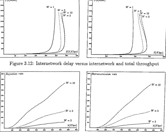
3.12 Internetwork delay versus internetwork and total throughput 37 3.13 Rejection and retransmission rates of internet messages 37 3.14 Internetwork delay versus internetwork load with unlimited
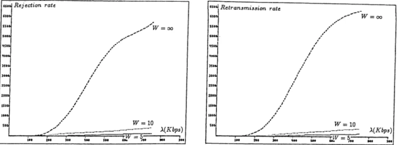
w i n d o w ... 38 3.15 Rejection and retransmission rates with unlimited window . . 38 3.16 Internetwork message characteristics for different buffer sizes 39 3.17 Internetwork throughput versus internetwork load in the token
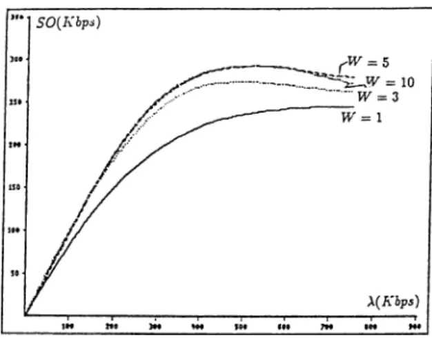
r i n g ... 40 3.18 Total throughput versus internetwork load in the token ring . 41
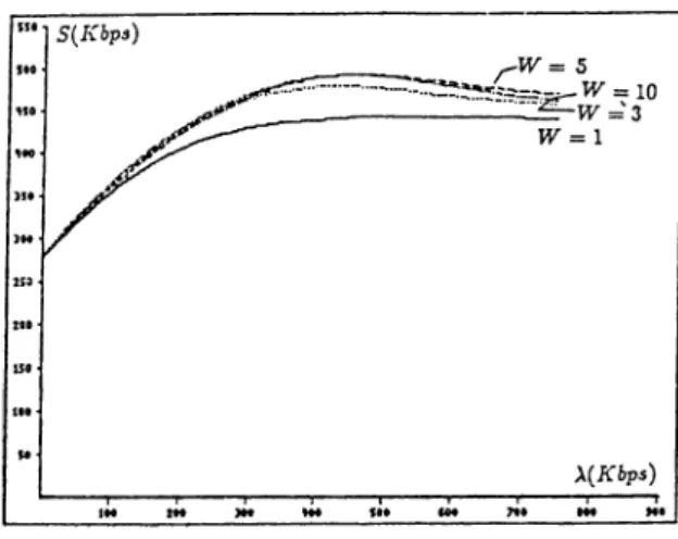
3.19 Throughput versus internetwork load 41
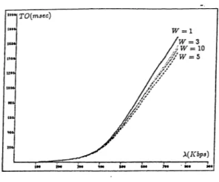
3.20 Internetwork delay versus internetwork load in the token ring 42 3.21 Internetwork delay versus internetwork and total throughput 42 3.22 Rejection and retransmission rates of internet messages . . . 43 3.23 Internetwork message characteristics with unlimited window . 44 3.24 Internetwork message characteristics for different buffer sizes 45
4.1 Various network characteristics for static window control . . . 51 4.2 Total throughput and internet delay characteristics with Al
gorithm! for the different threshold values of rejection rate . 52 4.3 Total throughput and internet delay characteristics with Al
gorithm! for the different threshold values of buffer utilization r a t e ... 52 4.4 Total throughput and internet delay characteristics with
Al-gorithm2 for the different threshold values of retransmission r a t e ... 53 4.5 Total throughput and internet delay characteristics with
Algo-rithm2 for the different threshold values of message response t i m e ... 53
4.6 Different performance characteristics of a network for static and dynamic window control with CSM A/CD medium access method within the network ... 55 4.7 Different performance characteristics of a network for static
and dynamic window control with token ring medium access method within the n e t w o r k ... 56 4.8 Average internet delay versus total throughput for different
number of networks connected to in tern etw ork ... 57 4.9 Average internet delay versus total throughput for different
buffersizes of destination gatew ay... 58 4.10 Average internet delay versus total throughput for different
gateway service ra tes... 59
LIST OF TABLES
3.1 Structure of an event list element ... 27 3.2 System parameters in simulation m o d e l ... 31
1. INTRODUCTION
1.1
C O M P U T E R N E T W O R K S A N D IN T E R N E T W O R K
IN G G A T E W A Y S
’ Computer network’ is a collection of ’computers’ or ’hosts’ which provide computing services to users. Communication of these computers are pro vided by means of special purpose communication processors called ’nodes’ , connected by some communication medium. The nodes and communication lines together form the ’communication subnet’ [39].
There are two types of communication subnet:
• store and forward (point-to-point) subnet, • broadcast subnet.
In the first one communication lines connect a pair of nodes. If two nodes don’t share a channel, they communicate indirectly via other nodes. When a
o
Figure 1.2: Some possible point-to-point topological configurations
Q O
satellite
6
a) Bus
0 ^ ~ 6bjSatellite
c)Ring
Figure 1.3: Broadcast topological configurations
message is sent from one node to another, it is received at each intermediate node, stored until the required line is free, and then forwarded.
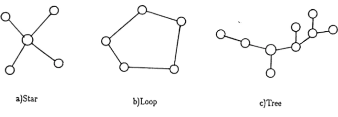
For point-to-point channels, node interconnection topology is an impor tant design issue. Examples of different point-to-point network topologies are given in Fig. 1.2.
In broadcast subnets, there exists a single communication channel shared by all o f the nodes. A message sent by a node is received by all other nodes. The nodes not intended to be a destination, just ignore the message. Some possible topologies for this type of networks are given in Fig.1.3.
The communication among all components of computer networks is reg ulated by a set o f rules called ’protocols’.
In computer networks, there are two general modes of message transfer between nodes. Either ’packet switching (datagram)’ or ’virtual circuit ’ technique is used during the communication of network components.
In packet switching networks, a message is divided into packets. Each packet has a maximum length and is independently routed through the net work. Its routing and transmission through the network is done on the basis of the destination node identification contained in the packet header.
Since each packet is routed independently, the packets injected into the network in a given sequence can arrive at the destination out of sequence. Therefore packet switching networks are non-order preserving.
Another characterization of datagram networks is loss of packets due to discarding them when there exists a shortage of network resources. It is also possible to have duplicate copies of a packet in transit. These duplicates are because of a channel or node failure, and two copies of a packet can arrive at the destination.
In virtual circuit networks, a path is established at the beginning of the communication to be used during the transmission between the sender and receiver. The packets contain virtual circuit number in stead of full receiver address. The packet sequencing is maintained within the virtual circuit.
’ Gateways’ are used to connect computer networks. Typically, a gateway is a computer system which switches data between networks. An ’inter connected network’ ( ’internetwork’ or ’internet’ for short) is a collection of networks whose protocols may be different. The function: of the gateway is to convert packets from one protocol to another. If the connected networks use different length packets, gateways also perform the function of packet length conversion by fragmentation and reassembly of packets [39].
Gateway applications differ mainly in the types of networks intercon nected. The simplest level of internetworking gateway is a ’bridge’ connect ing similar types of networks. Here no protocol conversion is required. The bridge receives packets from one network, stores them and then retransmit them to the other network.
With the evolving technology of internetworking, communication among different types of networks has become possible. In the connection of various types of networks, gateway application levels change based on the level of pro tocol layers the networks agree with. This type of gateways perform certain level of protocol conversion [2]. The packets received through one protocol structure, passed across a protocol translator, and transmitted through the other protocol structure.
We can give two examples of internetworking, which are radically differ ent approaches based on the type of service offered. The CCITT internet protocol, called X.75, is based on the virtual circuit model. An internetwork connection is built up by concatenating a series of intranetwork virtual cir cuits. During the flow of packets along a path, each gateway converts packet formats and virtual circuit numbers as needed.
The alternative internetwork model to C C ITT’s is the datagram model. This model doesn’t require all packets belonging to one connection to traverse the same sequence of gateways. Packets from a source to a destination take a variety of different routes through the internetwork. It is not guaranteed that the packets arrive at the destination in order, assuming that they arrive at all.
1.2
C O N G E S T IO N C O N T R O L
A computer network cannot accept all the data traffic that is offered to it beyond the capacity of its resources. The network may become subject to congestion with increasing traffic if an effective control mechanism does not exist. The congestion gives rise to a degradation in throughput (number of messages handled successfully per unit time) and an increase in average delay of messages. ’ Congestion Control’ corresponds to a mechanism that controls the traffic to reduce the overload on the network. The objective of congestion control is to prevent or minimize the adverse effects of congestion on the network performance.
Congestion control is one of the most important factors in determining the performance of a computer network. Total throughput o f the network, response time of the messages, and the utilization of network resources are highly dependent on the congestion control policy used. All computer net works use some form of congestion control for efficient and fair usage of their resources.
In interconnected networks, if the internetwork traffic constitutes the main portion of the total traffic within a network, then the performance of the network is affected heavily by this class of traffic. Congestion control in interconnected networks is intended to prevent the congestion at gateways along the path of the messages and at the destination network.
1.3
P U R P O S E A N D SC O P E OF T H E TH ESIS
In this thesis an internetwork model is provided and some congestion control mechanisms are proposed and evaluated in preventing congestion in gateways and in attached networks caused by the overload of internetwork traffic.
In chapter 2, a survey is provided for the most representative congestion control techniques that have been proposed or implemented. It presents the definition, functions, and different methods of congestion control concept in computer networks. The implementation of various congestion control mechanisms in some major operational networks is also discussed in that chapter.
In chapter 3, the internetwork model we have studied on and the in ternetwork message transfer protocol used are presented. The effectiveness of a window-based congestion control mechanism is evaluated. A brief de scription of the simulation program that was developed on the basis of the internetwork model is provided. The effect of internetwork traffic and various other internetwork parameters on the performance of a network connected to the internet is evaluated. Performance results are presented for two dif ferent medium access protocols: CSM A/CD and token ring, adapted for the transmission of messages within the network.
In chapter 4, two dynamic congestion control algorithms are proposed and studied. The algorithms are applied to the same internetwork model and provide further control to window mechanism by adjusting the window size in accordance with the current system load and availability of resources. An evaluation of control algorithms is provided in terms of the network per formance. Dynamic algorithms are evaluated as compared to static window control and it is shown that the algorithms have considerable performance advantages over the static window control.
2.
A SURVEY OF CONGESTION
CONTROL IN COMPUTER NETWORKS
This chapter provides a survey of various congestion control techniques in computer networks and current implementations of these techniques in some operational networks.
2.1
C O N G E S T IO N C O N T R O L IN C O M P U T E R N E T
W O R K S
A computer network may be thought of as a collection of resources that are shared by competing users [26]. The resources include communication channels, processing power, and buffers in the nodes. The capacity of the resources is limited, and if the user demands exceed this capacity, the system performance will be degraded. The overloaded network is said to be ’con gested’ . If the exceeded demands are not controlled, the network throughput will continuously decrease (Fig.2.1).
The set of control procedures which axe used for eliminating congestion is called ’congestion control’ procedures. There are two basic functions of these procedures [27]:
• Detection of congestion, and
• Activation of a suitable control procedure.
Congestion control is necessary for efficient, smooth, and fair transfer of all possible type of information. The quality of the computer network performance is highly dependent on the effectiveness of the congestion control policy used, since it provides the management of the network resources. Fair allocation of the resources between independent users is also intended by these control procedures.
Congestion control procedures include a set of constraints on the network resources and throttles the flow of traffic entering the network. The objective is to prevent throughput degradation and loss of efficiency due to overload. In other words, congestion control is intended to create a loss of traffic sufficient to maintain the level where maximum throughput is achieved.
Congestion control procedures can be implemented both in paclcet switch ing and virtual circuit networks [11],[12],[15],[27],[31].
There is some confusion in the literature between the terms ’congestion control’ and ’flow control’ . Congestion control is primarily concerned with controlling the traffic to reduce the overload on the network [23]. It corre sponds to mechanisms that prevent or minimize loss of throughput as the load on the network increases. ’Flow control’ is an agreement between a source- destination pair to limit flow of packets without taking into account the load on the network. By this mechanism the sender is controlled by receiver to prevent data from arriving at a faster rate than the receiver can handle it. In other words, the objective of the flow control is to prevent the traffic from entering the network which can not be carried to its destination.
Some authors consider congestion control to be a special case of flow control. But in most cases these two terms are used interchangeably and we will use the term ’congestion control’ to mean both.
2.1.1
C O N G E S T IO N C O N T R O L P E R F O R M A N C E M E A
SURES
Besides the functions mentioned above, there are other objectives of conges tion control that are at least as important. These objectives include:
• maximizing throughput,
• minimizing response time of messages.
Throughput is an important measure of congestion control performance. Total throughput (expressed in packets/seconds or bit/seconds) is evaluated as a function of offered load.
Transmission delay of messages may result from the saturation of shared resources. When message delays increase, the current traffic will rise rapidly. In this case some limitation mechanisms will be useful in preventing large delays. A timer can be set for each message travelled (timeout mechanism), or a threshold can limit the number of unsuccessful attempts in sending messages.
Another common measure is the combined delay and throughput per formance. In general, it gives us a more complete description of a system performance than the throughput behaviour alone.
2.2
C O N G E S T IO N C O N T R O L T E C H N IQ U E S
Various levels of controlling the congestion in computer networks have been suggested and implemented [11],[31]. We can categorize these levels in three groups:
• End-to-end congestion control, • Network access congestion control,
2 .2 .1 E N D - T O - E N D C O N G E S T I O N C O N T R O L
This category of congestion control is applicable to source-destination pair. End-to-end congestion control is the set of mechanisms where destination maintains the sender traffic within the limits compatible with the amount of resources available at the destination. An important function of such control is synchronization of source input rate to sink acceptance rate [27].
End-to-end congestion control methods work by limiting the number of packets permitted from source to destination. Most of them are based on some ’window’ mechanism that allows only up to a certain number of packets to be sent by sender before receiving an acknowledgement.
The ’window size’ is an important parameter in all of the window control mechanisms and this value may be either static or dynamically changeable depending on the protocol.
Performance analyses of computer networks with window congestion con trol was studied by Reiser [33], Thomasian [40], and Ilyas [18]. Reiser uses a closed queuing network model to analyze window control applied to virtual circuits of a computer network. An iterative scheme based on Mean Value Analysis (MVA) is presented to solve the network.
In [40] a solution procedure for obtaining individual virtual circuit and network performance measures is presented. The model allows both fixed rate and variable rate traffic sources. Using the model, measures of net work performance are computed for several network configurations. These results are used to study the relationship between virtual circuit path length and the optimal virtual circuit window sizes which maximize overall network performance.
Ilyas and Mouftah [18] present the analysis of an end-to-end window con gestion controlled network using a hybrid switching technique.
Gerla [13] proposes an algorithm for the optimization of window sizes in a window controlled network for congestion control and fairness requirements.
Another category of congestion control is network access level congestion control.
The congestion condition is determined at or is reported to the network access points and it is used to regulate the access of external traffic into the network. External traffic is throttled to prevent overall internal buffer congestion. The measurements of internal network congestion may be local due to buffer occupancy in the source node or global due to total buffer occupancy in the entire network.
The most popular implementation of network access congestion control is the ’isarithmic scheme’ . It was first proposed by Davies [9]. In this scheme the number of packets in the network is kept below a certain threshold which can be considered as the maximum network load. There exists permits circulating about within the network. When a node wants to send a packet, it first captures a permit. When the destination node removes the packet from the network, it regenerates the permit [39].
An analysis of computer networks with isarithmic congestion control is presented by Wong and Unsoy [47]. They analyze networks with two levels of congestion control. The first level controls the congestion on a global basis by limiting the total number of messages in the network over all message classes (i.e. isarithmic control), while the second level of control operates at the virtual circuit level by limiting the maximum number of messages that each virtual circuit can have (i.e. virtual circuit window size).
The critical parameters of the isarithmic scheme are the total number of permits and the maximum number of permits that can be held at a node. Al though this method guarantees that the subnet as a whole will never become congested, there could appear locally congested areas because of unbalanced traffic. Another problem here is that permits can get destroyed for some reason and there is no easy way to find out how many permits exist in the network.
Ilyas [19],[20] proposes several schemes for distribution of permits and effects of these schemes on the performance of computer networks.
’Input buffer limit’ control method differentiates between input traffic (i.e. traffic from external sources) and transit traffic. The input traffic is throttled
at the source, rather than global congestion as does the isarithmic method. The function of this control mechanism is to block input traffic if certain buffer limits are reached in the entry node. This approach favors transit traffic over input traffic. This is a desirable property since a number of network resources have already been invested in transit traffic [15],[27].
An implementation of input buffer limit was suggested by Kamoun [24], in which an input packet is discarded if the total number of packets in the entry node exceeds a given limit. Transit packets can freely claim all the buffers. This scheme is called drop-and-thx'ottle congestion control policy since under heavy traffic conditions it reduces the rate of input traffic (throttling mech anism), and transit traffic that arrives at a congested node is dropped from the network (dropping mechanism).
’ Choke packet’ control scheme is another network access control mech anism. It is based on the notion of link and path congestion. A link is defined to be congested if its utilization exceeds a certain threshold. A path is congested if any of its links is congested. When a node receives a packet directed to a destination whose path is congested, it drops the packet if it is an input packet. On the other hand, if the packet is a transit packet, it is forwarded but a ’choke’ packet is sent back to the source informing it about the congested path and instructing it to block subsequent input packets to this destination. The path to the destination is unblocked if no choke packet is received during a specified time interval [11],[39].
A variation on this congestion algorithm is to use queue lengths instead of link utilization in the determination of choke packet generation.
2.2.3
N O D E -T O -N O D E C O N G E S T IO N C O N T R O L
Throughput degradation and deadlocks are two unpleasant consequences of congestion in store-and-forward networks. To eliminate these effects, node- to-node congestion control procedures monitor buffer occupancies at each node and reject the traffic arriving at the node when some predetermined limits are exceeded.
The first example to node-to-node conti'ol is ’channel queue limit’ conges tion control. Each node distinguishes the incoming messages based on the output queue they must be placed into. The number of message classes is
equal to the number of output queues. There are some predefined limits on the number of buffers for each output queue; packets beyond this limit are discarded.
In the channel queue limit control method minimum and maximum limits on the number of buffers of a node can be set for each class. In different versions of the method, buffers on a node can be completely reserved to different classes or can be shared among all classes. It is possible to change buffer parameters dynamically in time. Basic buffer strategies are given in [111,[22],[48].
Another node-to-node control technique is ’structured buffer pool conges tion control’ whicli was proposed by Raubold and Haenle [32]. This scheme distinguishes incoming packets based on the ’hop count’ (i.e. the number of network links so far travelled). A number of buffers axe allocated to each class. Class i-|-l can access all the buffers available to each class i plus one additional buffer. If the buffers at level <i are full, then incoming packets with class <i are discarded.
An external packet from a host can only be admitted to the subnet if buffer for class 0 at the source node is available.
The channel queue limit and structured buffer pool control mechanisms are applicable to both datagram arid virtual circuit networks. In addition, selective control can be applied to virtual circuit networks in node-to-node level. In this case, the congestion control method distinguishes packets ac cording to the virtual circuit they belong to , if a virtual circuit architecture is used. A maximum limit is set on the number of packets for each virtual circuit stream that can be in transit at each intermediate node.
The limit may be fixed at virtual circuit setup time or may be dynamically adjusted based on the current load. The advantage of this scheme is to provide a more efficient recovery from congestion by selectively slowing down the virtual circuits directly feeding into the congested area. Although various buffer sharing policies can be proposed, most of the implementations employ dynamic buffer sharing.
Schwartz and Saad provide a survey of congestion control modeling and analysis techniques in [35]. Some quantitative methods are developed for evaluating the relative performance of various congestion control techniques.
2.3
C O N G E S T IO N C O N T R O L IN IN T E R N E T W O R K
IN G G A T E W A Y S
Since the gateway resources are not unlimited, congestion problem also exists in gateways. When the internetwork traffic transmitted to a network via its adjacent gateway increases without control, the network and its gateway will be subject to congestion. The congestion control in gateways is intended to prevent congestion in gateways and in attached networks caused by internet work traffic.
It is possible to call this level of congestion control, the gateway-to- gateway level [11]. The level should be designed to prevent the congestion of gateways along the path, and should be supported by explicit gateway-to- gateway protocols for the exchange of status information. The status infor mation should include buffer occupancy at the gateway, and load conditions in adjacent networks.
The actual implementation of the internetwork congestion control will be dependent on the internet protocol used. If the CCITT X.75 protocol is adopted, internet congestion control will be virtual circuit oriented, and will be exercised on a connection-by-connection basis. Alternatively, datagram oriented internetwork congestion control schemes can.,also be implemented. It is possible to say that, many congestion control methods implemented in computer networks are also applicable at gateway level.
The design of efficient gateway congestion schemes requires a consistency between the gateway level and all other levels implemented in each individual network as well as a consistency across the various networks on the internet path. Internetwork congestion control must be able to balance loads between diverse networks environments.
Some examples of the performance studies of congestion control policies in the interconnected networks can be found in [4],[16],[30],[46].
2.4
E X A M P L E S OF C O N G E S T IO N C O N T R O L IN
V A R IO U S N E T W O R K S
2.4.1
C O N G E S T IO N C O N T R O L IN T H E A R P A N E T
The ARPANET [28] is the creation of DARPA, the Defense Advanced Re search Projects Agency of the U.S. The ARPANET communication subnet uses datagrams inside but provides virtual circuit service to the hosts.
For end-to-end congestion control in ARPANET, all messages transmitted from a source host to a destination host are carried on the same logical ’pipe’ . Each pipe is controlled by a window mechanism. Correctly received messages are acknowledged with end-to-end control messages, called RFNM (ready for next message). The source node of the pipe advances its transmission window after receiving an RFNM. RFNM’s are also used for retransmission purposes. If an RFNM is not received within a specified timeout, the source sends a control message to the destination inquiring about the possibility of mes sage lost. The destination can request a retransmission after an incomplete transmission.
Messages flowing on a pipe are numbered sequentially. Message num bers are checked at the destination and the messages arriving unordered are discarded to prevent resequence deadlocks.
If multipacket messages are transmitted between a pair of nodes, the destination node must reassemble packets into messages. In the ARPANET possible reassembly deadlocks are prevented by requiring a reassembly buffer reservation for each multipacket message entering the network.
DARPA INTERNET
The DARPA Internet architecture is defined by protocols TCP (transmis sion control protocol) and IP (internet protocol). The IP defines a datagram based service that allows a host on one network to send datagrams through one or more gateways to a host on another network. Datagram delivery is not guaranteed. The TCP uses acknowledgement, retransmission, duplicate filtering, and other mechanisms to provide virtual circuit services built on top of the datagram machinery. The TCP will compensate for datagrams that are lost [17].
The implementation of virtual circuit service differentiates the DARPA interconnection approacli and others, such as the X,25/X.75 scheme. In the X .25/X.75 approach, each network implements a virtual circuit service, and X.75 gateways connect circuits together. In the DARPA Internet each under lying network has to provide reasonable datagram delivery service but need not implement virtual circuits.
CONGESTION CONTROL IN T C P /IP INTERNETWORKS
In heavily loaded datagram networks with end-to-end retransmission, if switching nodes become congested, both end-to-end delay and the total num ber of datagrams in transit will increase. When retransmission of datagrams begins, there exists a danger of congestion.
Host TCP retransmits packets several times at increasing time intervals until some upper limit on the retransmit interval is reached. Under normal load, this mechanism is enough to prevent serious congestion problems.
Another congestion control mechanism is sending a control message to the source, when a gateway finds itself becoming short of resources. Senders are throttled before they overload switching nodes and gateways. In general, the control message is sent when about half of the buffer space is exhausted. There exists other gateway implementations that generate the control mes sage to the sender only after one or more packets have'been discarded [29].
2.4.2
C O N G E S T IO N C O N T R O L IN G M D N E T
GMDNET is a virtual circuit network. The route of a message stream is determined at connection setup time and remains fixed until its clearing. Another design characteristics of this network is that the communication protocols are structured recursively. This means that the protocol controlling the message transfer of a virtual circuit between two adjacent nodes is equal to the end-to-end protocol being applied between source and destination node of a virtual circuit [15].
In GMDNET congestion control is provided individually on each virtual circuit. Control is performed between two adjacent nodes and between source and destination nodes according to the recursive communication protocol mentioned above. Both control principles are identical and based on a dy namically controlled packet window.
The main purpose of the source to destination (end-to-end) congestion control is to prevent the overflow at the destination node. Dynamic window size can be reduced if the destination node is slow in accepting packets.
The congestion control between adjacent nodes on the virtual circuit is also exercised independently. While end-to-end window is controlled by des tination buffer occupancy, node-to-node window is controlled by intermediate node congestion.
The experiments showed that the individual virtual circuit congestion control is not enough to prevent throughput degradation. So, the buffer space for the input packets at each node was restricted by introducing limits. However to only apply control by input buffer limits was not sufficient to guarantee high network performance. In order to get an effective congestion control, not only input class but also all other message classes should have been applied some limits. GMD network group developed input buffer limit congestion control technique for this purpose.
Fixed path routing in GMDNET provides packets arrive at their desti nations in sequence. This property eliminates the need for reassembly buffer allocation which is implemented in ARPANET.
2.4.3
C O N G E S T IO N C O N T R O L IN S N A
SNA [8] is a network architecture developed by IBM to allow its customers to construct their networks and provide distributed communication and dis tributed processing capabilities between these systems.
SNA is a virtual circuit network, such that at the beginning of each user session an available route is associated among several possible virtual routes. Several sessions may be multiplexed on the same virtual route.
IBM SNA networks use Virtual route pacing control’ mechanism in con trolling congestion. This mechanism is an example of an end-to-end window control mechanism. For each virtual route, a fixed window is initially estab lished and a pacing count at the source is set at this value. When a message enters the virtual route, the pacing count is decremented. The first message of the window generates an acknowledgement to the source when it arrives at the destination. The signal arriving at the source node causes the current pacing count to be incremented by the window size [36].
The window size of a virtual route gives the number of messages permitted by the destination to be sent by the source. This can be dynamically adjusted by the destination node and also intermediate nodes along the path on the basis of the buffer availability.
In [36] the performance of the IBM SNA virtual route pacing control mechanism and two variations are analyzed. Simulation is used to ascertain the accuracy of the analysis.
2.4.4
C O N G E S T IO N C O N T R O L IN T Y M N E T
TYMNET [41] is a commercial network originally developed to interface low speed terminals to time-sharing computers. It is probably the earliest virtual circuit network. TYMNET is a character oriented network.
Each link between two adjacent nodes is divided into channels, and a virtual circuit passing over that link is assigned to a channel. Data from various channels may be combined or multiplexed into one physical packet to share the overhead of checksums and headers among several low speed channels. A high speed channel may use the whole physical packet by itself.
In the congestion control of virtual circuits, for each channel on a link between two nodes, there is quota of bytes which can be transmitted. This quota is assigned at the virtual circuits setup time and varies with the load of the circuit. When a node has exhausted the quota for a given channel, it can not send any more on that channel until the quota is refreshed from the other node. The destination node sends back permission to refresh the quota when it doesn’t have much data buffered and the quota is low or exhausted. Doing nothing is the way to throttle the data at the source. This backpressure scheme provides that if a node is overloaded, one effect of the overload is to reduce the load [42].
2.4.5
C O N G E S T IO N C O N T R O L IN D A T A P A C N E T
W O R K
DATAPAC [5] is the Canadian public data network, providing virtual circuit service built on a datagram subnetwork. The main communication layers (i.e. virtual circuit and datagram subnet layers) of the DATAPAC network
apply different congestion control policies. DATAGRAM CONGESTION CONTROL
Datagram congestion may be due to a variety of factors including in sufficient buffer space, insufficient channel capacity, or a network overload. Regardless of the cause, the congestion will always cause a depletion of com munication memory buffers.
When congestion of common memory occurs, the basic mechanism to re lieve congestion in DATAPAC networks is to discard subnet datagrams. This event backs up the congestion to the virtual circuit layer of communication (i.e. the virtual circuit layer holds a copy of the packet at the source up to T seconds while waiting for an acknowledgement of transmission across the subnet. If the timer T expires, retransmission of the packet will occur). The virtual circuit layer will control the external rate of packet arrivals ac cording to the rate at which they can be successfully transmitted through the subnet. This feedback mechanism will clear the congestion situation by throttling additional input into the network.
If a packet doesn’t get through the subnet after four retransmission at tempts by the virtual circuit, then the problem is considered serious enough to clear the virtual circuit call.
The policy for determining the datagrams to be -discarded affects the robustness and stability of the system. The policy implemented in DATAPAC gives precedence in access to buffers to datagrams already within the subnet over datagrams just entering the subnet. A threshold is set on available memory buffers, below which no additional datagrams are admitted to the network [38].
VIRTUAL CIRCUIT CONGESTION CONTROL
The basic communication service offered in the DATAPAC network is a virtual circuit service. The virtual circuits make use of the datagram sub net for internode communications. No physical path is actually assigned to virtual circuit as in SNA and GMDNET.
The virtual circuit is implemented as the concatenation of three protocol segments: a protocol from the source device to entry node, a protocol from entrj'^ node to exit node, and a protocol from exit node to destination device. Once a virtual circuit is established, congestion control is maintained by
a set of three windows for each direction of transmission: a local access window, a subnet access window, and a remote access window. Window sizes are statically assigned for each access line according to the type of service supported (e.g. large windows are assigned if high virtual circuit throughput is required).
The virtued circuit congestion control is very much as described in previous section, that is, subnet congestion backs up to the virtual circuit layer; and the virtual circuit applies control on the external packet arrivals.
GATEWAY CONGESTION CONTROL
DATAPAC internetworking is realized through interface based on CCITT Recommendation X.75 between adjacent networks. Virtual circuits fixed to X.75 gateways will be subject to the same subnet and virtual circuit conges tion controls as outlined before. However some additional control is required to prevent a large number of virtual circuits exceeding the capacity of the gateway links. The control is provided by limiting the number of incoming calls and the number of outgoing calls that may be simultaneously established across each gateway link.
3. WINDOW BASED CONGESTION
CONTROL IN INTERCONNECTED
NETWORKS
This chapter provides a model for the evaluation of congestion control in interconnected networks. Internetwork message transfer is controlled by a window mechanism to prevent message overload at the gateways and con nected networks. The window mechanism provides the control by restricting the number of messages in transmission between a source-destination network pair.
3.1
T H E M O D E L
Fig.3.1 presents the internetwork structure we study on where the individual local networks are connected to the system via their gateways.
Gli
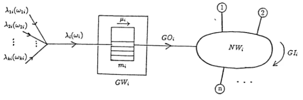
Figure 3.2: Model for a destination network and adjacent gateway Our study is concerned primarily with investigating the effect of internet work traffic on the performance of connected networks and providing gateway- to-gateway level congestion control to prevent internet message overload at the gateways and networks. In Fig.3.2 a model is provided for a network and its adjacent gateway within the internet.
Internetwork message transfer is controlled by a window mechanism. Each network is allowed to send up to a fixed number of messages to another net work without getting acknowledgement. The fixed number gives the ’window size’ between a network pair.
Let G W i (gateway i) be the representative gateway model and N W i (net work i) be its connected network (Fig.3.2). It is assumed that there are k networks connected in the system. The effect of the internetwork traffic transmitted to N W i will be investigated. The following parameters can be given for 1 < j < k :
W j i ( p a c k e t s ) : Window size for internet messages from N W j to N W i where j ^ i. The messages in the system will consist of one packet; so the window size can be given in packets.
j j i ( p a c k e t s / s e c o n d ) : Generation rate of internet messages at N W j to be destined to N W i where j ^ i. The arrival process of internet messages is poisson.
T(seconds) : Timeout period for the internet messages. If an internet message is not acknowledged within the period r, it is retransmitted by the source network.
u jji(p a c k e t s ) : Number of packets (from N W j to N W i ) currently in the system.
iOi = (wii,u;2t·, · Collection of currently existing packets destined to N W i .
X j i { u j j i ) ( p a c k e t s /s e c o n d ) : Effective arrival rate of internet messages from N W j to N W i .
Jji i .f ^ j i < W j i
0 otherwise
Xi(u}i) : Total effective arrival rate of internet messages to G W i . k
t
i {^ji
)i=i
P i ( p a c k e t s / s e c o n d ) : Message processing rate at G W i . Service time dis tribution is exponential.
m i ( p a c k e t s ) : Buffer capacity of G W i . The packets residing on the buffers are serviced in a FCFS (First Come First Served) order.
ni : number of nodes within N W i
G l i i jp a c k e t s / s e c o n d ) : Total intranet traffic rate within N W i . It is the sum of the rate of internal messages generated by all of the nodes. Arrival of internal messages is also assumed to be a poisson process.
C i ( b i t s / s e c o n d ) : Speed (capacity) of the N W i .
K b i t s / p a c k e t ) : Average message(packet) length (both internet and in tranet). Message lengths are exponentially distributed with expectation 1.
G O i i j p a c k e t s /s e c o n d ) : Rate of internet packets processed at G W i to its destination (i.e.A'W,·). G O i is a function of parameters A,(o;,),/Xi,m,·. An analytical derivation of this parameter is presented in Appendix A.
The throughput and delay ¡Darameters of the messages within N W i can be given as:
T O i(^ s e c o n d s ) : End to end delay of internet messages. T l i ( s e c o n d s ) : End to end delay of intranet messages.
3.2
IN T E R N E T M E S S A G E T R A N S F E R P R O T O C O L
The internet message transfer protocol used in this system makes the source network stop sending packets to a destination network if the number of unac knowledged messages sent by the source network to the destination network reaches to the window , size limit of the corresponding network pair. Fur ther arrivals of messages have to be blocked at the source. For each packet successfully received, an acknowledgement is generated by the destination. Each packet sent by the source network causes a one unit incrementation of current window, and each acknowledgement from the destination decrements the window by one unit.
The resource limitations for internetwork messages arriving at the desti nation gateway are gateway buffer size, gateway message service rate, and the link capacity of the network connected to the gateway. After processed by the gateway, an internetwork message will be ready to be transmitted to its destination node within the network. It will then compete with the other internet and intranet messages for the network link capacity.
Some of the internet messages can be discarded at the destination gateway because of unavailable buffer space. A copy of each packet is kept at its source until the acknowledgement of that packet returns from the destination. If the acknowledgement doesn’t come within a prespecified period of time (i.e. timeout period), the packet will be retransmitted.
The next section presents the description of CSM A/CD and token ring access protocols which are adapted to the network model under consideration for the transmission of both internet and intranet messages.
3.3
N E T W O R K AC C E SS P R O T O C O L S
3.3.1
N O N P E R S IS T E N T C S M A /C D
The first protocol we have used for the transmission of messages accessing our network is nonpersistent Carrier Sense Multiple Access with Collision Detection (C SM A /C D ) protocol.
CSMA protocols are used in random access networks where a common channel is shared by the nodes and each node operates independently of the other nodes. There is no central control or channel-controlled access mechanism for random access networks. Each node is free to transmit its packet at a time determined by itself [14],[39].
CSMA protocols are refinements of ALOHA protocols [1], with the re finements through sensing the transmissions of other stations. A node of the CSMA network listens to the channel before transmitting a packet. If the channel is sensed to be busy, the station can defer its transmission until the channel is sensed to be idle.
If two or more users decide to transmit at almost the same time, they can sense the channel as idle and try to transmit. Their packets will overlap on the channel. Such an overlap of packets is called a ’collision’ . When a node learns that its transmission is unsuccessful, it reschedules the transmission of the packet to a later time by using some specified backoff algorithm. After the backoff, the node again senses the channel to send its packet.
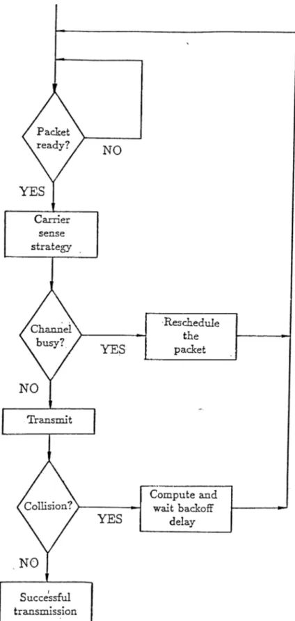
There are two general classes of CSMA protocols, nonpersistent and per sistent, based on the usage of carrier-sense information. In nonpersistent CSMA protocol, when a node becomes ready, the channel is sensed to see if anyone else is transmitting. If the channel is sensed idle, the packet is transmitted; if the channel is sensed busy, the node reschedules the packet to a later time. After that random period of time, the channel is sensed again, and the algorithm is repeated.
In persistent CSMA protocol, when a node has data to send, it first listens to the channel. If no one is sending, it transmits the packet. Otherwise, if the channel is sensed bus}'^, the node keeps on sensing the channel until the channel goes idle, and then it transmits. In other words, the channel is continuously sensed for the purpose of seizing it immediately upon detecting
Figure 3.3: A typical ring structure the end of the previous transmission.
A further improvement on random access networks is possible by the use of carrier sense multiple access with collision detection (C SM A /C D ). Colli sion detection, also called ’listen while transmit’ , makes it possible to detect a collision shortly after it occurs and terminate transmission immediately, minimizing the channel time occupied by unsuccessful transmissions. To im plement the additional feature of collision detection, the transmitter must include hardware not only for transmitting and monitoring, but, in addition, monitoring while transmitting.
In random access networks, the minimum time to detect the collision is the time it takes the signal to propagate from one station to the other. This time interval is called propagation delay and it depends on the physical length of the channel. For carrier sensing to be effective, propagation delays must be less than packet transmission times. The ratio of propagation delay to packet transmission time is an important parameter in performance studies of CSMA.
3.3.2
T O K E N R IN G P R O T O C O L
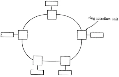
The second protocol adapted to the local network of our model is a popular kind of ring networks called token ring. The organization of ring networks is different from carrier sense networks. A ring network can be characterized as a sequence of point-to-point links between consecutive nodes (Fig.3.3) [10],[14],[39].
passing through network interfaces at each node. Each node is active in the sense that it regenerates the message and can identify addresses, but the interface unit does not usually store messages, as in a store-and-forward network. Each node passes the message on after a short delay of few bit times.
A token ring has the basic structure of all ring networks. Bits from the ring enter the interface in one direction in a serial fashion, are read in the interface, and then after a delay of several bits, are retransmitted over the ring either unchanged or after some modification.
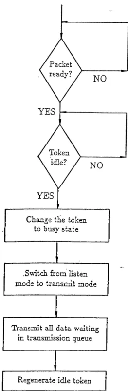
Access to the ring for transmission is controlled by a token, which is a bit structure that can be in one of two possible states: busy or idle. An idle token circulates around the ring whenever all nodes are idle. When a node has data to transmit reads the idle token and changes it to busy state before transmitting it. The busy token then becomes a part of the header of data transmitted on the ring. Thus other nodes on the ring can read the header, note the busy token, and refrain from transmitting. Since there is only one token, there is never any contention as in CSMA networks.
Typically, the token can be a dedicated pattern of several bits. It must be ensured that the bit pattern for a token does not occur in the data. This is accomplished by monitoring the data and using ’bit stuffing’ , a procedure that breaks-up any data pattern that duplicates the token by adding or ’stuffing’ extra bits. When stuffing has been used, the receiver must be able to identify the stuffed bits so that they can be removed before error detection.
There are two operating modes of ring interfaces, listen and transmit. In listen mode, the inputs are simply copied to output. In transmit mode, a node can transmit its data after changing the state of the idle token.
When the data bits that have been propagated around the ring come back, they are removed from the ring by the source node. After finishing the transmission of the last bit of data, the source regenerates the token and switches the interface back into listen mode.
In the listen mode, each node passes on the packet received at its input after a delay referred to as the ’node latency’ . The token circulates around the ring in a time equal to the sum of propagation delays between nodes plus the sum of the node latencies. This composite time is called ’ring latency’ .
mesno arrtime time mestype source next
Table 3.1: Structure of an event list element
ring, there are two types of operation: exhaustive service and nonexhaustive service. For exhaustive service, the node retains use of the ring until it has transmitted all the data stored in its buffer. For nonexhaustive service, the node is allowed to transmit only a specified number of packets.
3.4
S IM U L A T IO N P R O G R A M
A simulation program has been developed on the basis of the model discussed in the previous sections. The program simulates a network and its adjacent gateway that provides the connection of the network to the internet. End-to- end message transfer in the internet is controlled by the source-destination gateway pairs. Gateways provide the control by restricting the number of in ternet messages in transit between networks. This restriction is aimed for the fair transmission of internet messages. In other words, internet message over load on the gateways and networks is prevented by assigning proper ’window sizes’ between networks.
The simulation is event driven, that is the simulation clock is advanced cifter simulation of an event to the time of the next event to simulate its action. The event list is stored in a linked list structure ordered by event times. Each event list element is a message generated in the representative network or a message destined to the network from other networks. Each list element consists of time fields, data fields, and a pointer to the next event in the list (Table 3.1).
’Mesno’ field of message is used to identify the message in the network. ’Arrtime’ field stores the generation(arrival) time of a message. In the ’time’ field the time of the current event for the message is stored. Possible events include the message generation, message transmission, retransmission, and gateway service for the internet messages. The message list is kept sorted by this field.
’Mestype’ field specifies the type of message, whether it is an internetwork or intranetwork message. ’Source’ field stores the source network of an inter net message or the source node of a message generated within the network. The pointer ’next’ points at the next message in the list. If the CSM A/CD protocol is used, a ’collcount’ field is added to each message specifying the number of collisions of the message with the other messages in the network. This information is used during the rescheduling process.
At the beginning of the simulation process, internet and intranet mes sages are generated and inserted into the message list. Internet messages are generated exponentially with the specified average internet arrival rate. Each source network generates the messages independently from the others and networks can have different generation rates.
Intranet messages are generated within the representative network model. The nodes of the network are the sources of messages and the arrival of intranet messages is exponential with a mean of a specified intranet arrival rate. The gateway can be considered as another node of the network trying to transmit internet messages within the network.
A copy of an internet message is stored in a list at its source when it begins to be transmitted. The time field of the message copy includes the end of timeout period for retransmission. The gatew-ay maintains a list of messages that reside in its buffers.
When the transmission of a message is completed, the message is deleted from the message list. The copy of it is also deleted from the list kept at its source.
The assumptions for the internetwork simulation model are as follows.
• The arrival process of internet and intranet messages follows a poisson process.
• No multipacket message exists in the system, that is all messages con sists of only one packet.
• Message lengths are exponentially distributed with the average length of / for both internet and intranet messages. With this assumption, the service time distribution for the internet messages at the gateway and the message transmission time distribution for both types of messages within the network are exponential.
• The gateway has a finite number of buffers and each buffer can store only one packet.
• The transmission error rate is negligible.
The nonpersistent CSM A/CD network protocol adapted to the network model has the following properties:
• The nodes and the gateway compete for channel access.
• The arrival process to a particular node is deactivated until the trans mission of a packet already at the node is successfully completed. In the same way, the gateway tries to transmit the first message in its queue. • After a collision, binary backoff algorithm is used for rescheduling the
collided packets. After a successful transmission, the nodes compete for the channel. If there is a collision, all colliding nodes set their local collision count parameter to 2, and they distribute their transmission time over 2 message delay period. After each collision, the node involved in a collision doubles the value of its local parameter and retransmission time interval.
The nonpersistent CSM A/CD protocol applied to our network can be described with the flowchart of Fig.3.4.
The token ring network access protocol is used in the network with the following properties:
• Exhaustive service operation is used in the transmission of packets (i.e. when a node receives permission to send, it empties itself of all queued packets).
• When a node finishes its transmission and regenerates the token, the next node downstream will remove the token if it has data to send. In this manner the permission to send rotates smoothly around the ring in one direction.