T.C.
ISTANBUL AYDIN UNIVERSITY
INSTITUTE OF SCIENCE AND TECHNOLOGY
SMART GRID CYBER PROTECTION ALGORITHM DEVELOPMENT
THESIS Ahmet DURMUŞ
Department of Electrical and Electronics Engineering Electrical and Electronics Engineering Program
i T.C.
ISTANBUL AYDIN UNIVERSITY
INSTITUTE OF SCIENCE AND TECHNOLOGY
SMART GRID CYBER PROTECTION ALGORITHM DEVELOPMENT
M.Sc. THESIS Ahmet DURMUŞ
( Y1613.300014 )
Department of Electrical and Electronics Engineering Electrical and Electronics Engineering Program
Thesis Advisor: Prof. Dr. Mehmet Emin TACER
v
vii FOREWORD
I would like to thank my wife MAHA, mother AMINEH, father ADHAM, brother MOHAMMAD and my sisters HUDA, MUNA, and ASMA’A who had helped me to become a successful person. Giving to me all efforts, guiding me to correct all wrongs and learning from my mistakes. I hope I can return any of their rights over me and to give them all happiness for all of their lives.
Also I would like to thank my thesis advisor Prof. Dr. Mehmet Emin TACER for his guidance, support, and help during my work in the thesis.
Also, I thank all my teachers and friends starting from my school time until today as they had great influence on me to complete my education forward.
ix DECLARATION
I declare that the information in this document has been obtained and presented in accordance with academic rules and ethical conduct. I also declare that, as required by these rules and conduct; I have fully cited and referenced all material and results that are not original to this work.
x
TABLE OF CONTENTS
Page
TABLE OF CONTENTS ... x
ABBREVIATIONS ... xii
LIST OF TABLES ... xiv
LIST OF FIGURES ... xvi
ÖZET ... xviii
ABSTACT ... xx
1. INTRODUCTION ... 2
1.1 Definition of Smart Grid System ... 2
1.2 Comparison between grids and advantages ... 2
1.3 Smart Grid System Components ... 5
2. SMART GRID SYSTEMS TECHNICAL REVIEW ... 10
2.1 Orientation of smart power grid communication and networking: ... 10
2.2 Data storage in smart grid systems: ... 10
2.3 Information security requirements and challenges in smart grids:... 11
3. THEORITICAL REVIEW OF CYBER PROTECTION IN NORMAL POWER GRID ... 14
3.1 A proposed SCADA security protection framework ... 16
3.2 Attack Tree Modeling ... 18
3.3 Cybersecurity conditions and evaluation ... 19
4. CYBER PROTECTION OF SMART GRID SYSTEMS ... 24
4.1 Introduction ... 24
4.2 Proposed Smart grid Cybersecurity ... 25
4.3 Proposed Smart grid Cybersecurity Consumer Algorithm ... 32
4.4 Simulation of Proposed Smart grid Cybersecurity Consumer Algorithm ... 33
5. CONCLUSION AND FUTURE WORK ... 38
5.1 Conclusion and Recommendation ... 38
5.2 Future work ... 39
REFERENCES ... 40
APPENDICES ... 42
xii ABBREVIATIONS
NERC : North American Electric Reliability Corporation AMI : Advanced Metering Infrastructure
SCADA : Supervisory Control and Data Acquisition EMS : Energy Management System
SAS : Substation Automation System ISO : Independent System Operator
RAIM : Real-Time Monitoring, Anomaly Detection, : Impact Analysis, and Mitigation Strategies
DOS : Denial of Service
HP / MP / LP : High Power / Medium Power / Low Power TS / DS :Transmission Station / Distribution Station PCS : Process Control System
DMS : Distribution Management System
xiv LIST OF TABLES
Page Table 1.1: Comparison between traditional and smart grids ... 2 Table 4.1: Proposed hypothesis in AMI modeling ... 26 Table 4.2: Table of probability if 2 conditions are satisfied from proposed hypothesis in this study. ... 29 Table 4.3: Table of probability if 3 conditions are satisfied from proposed hypothesis in this study. ... 30 Table 5.1: Comparison between previous work and my proposed algorithm. ... 38
xvi LIST OF FIGURES
Page
Figure 1.1: Peak Reduction Concept ... 4
Figure 1.2:smart grid perspective with all components ... 5
Figure 1.3: Smart meters ... 6
Figure 1.4: Power generation,control,and measurement diagram ... 7
Figure 1.5: Smart Grid Infrastructure ... 8
Figure 3.1: RAIM Framework ... 16
Figure 3.2: Algorithm to evaluate vulnerability indices ... 19
Figure 3.3: Attack tree of normal power system control framework ... 20
Figure 4.1: Proposed connection between AMI unites and Smart meters ... 27
Figure 4.2: 5 Conditions Satisfied ... 34
Figure 4.3: 4 Conditions Satisfied ... 34
Figure 4.4: 3 Conditions Satisfied ... 35
Figure 4.5: 2 Conditions Satisfied ... 35
Figure 4.6:Appearing Message if 2,3 or 4 Conditions Satisfied ... 36
Figure 4.7: 1 Condition Satisfied ... 36
Figure 4.8: Appearing Message if 1 Condition Satisfied ... 37
Figure 4.9: Appearing Message if bugs are inserted or settings between SS and actual readings are not matching ... 37
xviii
AKILLI ŞEBEKE SİBER GÜVENLİĞİNE ALGORİTMA GELİŞTİRMESİ
ÖZET
Akıllı şebekeler, güçlerini dağıtmak ve farklı bileşenlerinde yüksek düzeyde teknik ve fiziksel güvenlikle doğru bir şekilde yönetmek için akıllı yollar kullanan gelişmiş bir ızgaralardır.
Bu tür şebekelerde, elektrik santrali ve tüketici ikiside güç tedarikçisi sayılır; çünkü akıllı şebeke sistemlerinde de tüketici ihtiyaçları karşılamak için evde veya iş yerinde bazı yenilenebilir enerji kaynakları kullanabilir. Her ikisi de kWh'den diğerine enerji üretebilir, alabilir ve satabilir. Buna nedeniyle, finansal kanallar da kullanması dahil edilmiştir, böylece her biri için gizliliğin güvenliği önemlidir.
Çalışmamız, akıllı şebekede veya mikrogrid’te saldır izole yapabilmesi, erişimin yeniden yetkilendirilmesi veya normal kullanıcılar tarafından yapılan finansal işlemlerine erişimin başarıyla kabul edilmesi için esnek bir yol uygulamsı kullanılan bir algoritma geliştirmekle ilgilenecektir. Buna rağmen saldırganın aynı kullanıcı olup olmadıklarını.
Bu, Akıllı Şebeke Sistemleri kullanarak tüketicilerin gücünün güvenli bir şekilde dağıtımına yardımcı olmak için geliştirilen yeni teknolojilerden önemini aldı.
xx
SMART GRID CYBER PROTECTION ALGORITHM DEVELOPMENT ABSTACT
Smart grids are an advanced grids that use intelligent ways to distribute power and manage it accurately with high level of technical and physical safety in its different components.
In these types of grids, the power station and the consumer are both considered as effective power supplier; because consumer also in smart grid systems uses some renewable energy sources in house or work place to cover needs. Both can generate, buy, and sell power as of kWh to the other. Thus, financial channels are also included, so that the safety of privacy for each of them are important.
Our study will be concerned on developing an algorithm used to apply a flexible way for determining to either isolate the network, reauthorize access, or successfully accept the access for financial transactions made by normal users. Despite of they are the same of attacker or not.
This took its importance from new technologies that developed to help in safely distribution of power to consumers using Smart Grid Systems.
2 1. INTRODUCTION
1.1 Definition of Smart Grid System
It is a type of grid that applies improvement of normal grids in a way of combination of computer-based systems of information technologies and traditional electrical grid. This type of grids uses two-way communication to enhance the network behavior in generation, consumption, reliability, stability and cost effect between the generation station and the consumer demand with momently updated information. Generally smart grid is contained of other small smart partitions - called as microgrids - each of them should be in connection with each other simultaneously.
1.2 Comparison between grids and advantages
Table 1.1: Comparison between traditional and smart grids [15]
Traditional Grid Smart Grid
Use One-Way Communication Uses Two-Way Communication Centralized Power Generation Decentralized or Distributed Power
Generation
Manual Monitoring Automated Monitoring
Small Number of Sensors Large Number of Sensors Among All Grid Parts
Failures Can Make Power Outage Failure Could Be Isolated If Any Manual Recovery of System Automatic Recovery of System
3 Advantages of smart grid systems [1]
1. Energy savings through reducing consumption:
One of the advantages of smart grids is that; it can tell us the consumption at energy meter at any time, so users are better informed of their real consumption.
2. Better customer service and more efficient billing information:
Smart grid systems always reflect the real consumption of each month instead of estimates, reducing the cost of the old system of manual energy meter readings. In addition to being able to access information about the installation remotely, problems become easier to diagnose and solutions can therefore be implemented faster, thus improving customer service.
3. Fraud detection and technical losses:
Smart grid systems can provide momently updated status of network health, reliability, stability, and any other instantly loss. If any loss happens it will isolate that area to not affect other parts of the system, and regarding that area it will keep on reduction of selected area to make the accurate error be detected correctly. This could be done according to multi feedback communication between each part of the systems, available smart meters, and active sensors.
4. Reduced balancing cost:
Smart Grids can collect much more data than the manual energy meter reading system. This permits the use of data analysis techniques and the preparation of highly realistic consumption forecasts as many more variables are considered.
5. Levelling of the demand curve (Peak reduction):
Using different pricing profiles, utilities can level out the daily demand curve to shift consumption peaks to times with lower demand, optimizing usage of the electrical network. So, customers can intentionally connect loads at off-peak times when each kWh is less expensive. As an example: a customer may decide to change their consumption habits by using any machine during off-peak hours, at night, instead of when each kWh is more expensive, saving money and helping the utility balance consumption and avoid line saturation during peak hours.
4
Having consistent consumption means that power plants do not have to switch on and off as many times to generate energy, which lowers generation costs.
Figure 1.1: Peak Reduction Concept
Using different pricing profiles, utilities can flatten the daily demand curve to shift consumption peaks to times with lower demand, optimizing usage of the electrical network.
6. Reduction of carbon emissions
All the benefits above involve reducing consumption, which entails a reduction in CO2 emissions.
Time Power
5 1.3 Smart Grid System Components
Figure 1.2:smart grid perspective with all components [2]
Smart grid systems have some main parts which is connected to satisfy the reliability and stability of system operations and those are :
1. Intelligent Appliances [3]: have capability of deciding when to consume energy based on customer pre-set preferences; in a way that can lead to going away along toward reducing peak loads which have an impact on electricity generation costs.
6 2. Smart Power Meters:
Figure 1.3: Smart meters [2]
Smart meters provide two-way communication between power suppliers and the end user consumers. Its role is to automate billing data collections, detect device failures and dispatch repair crews to the exact location much faster [3]. The mix between two way communication for control, gathering information, and monitoring in these electronic meters is widely known as Advanced metering infrastructure ( AMI ) [4].
In other words, functions of smart meters are: Precise metering, data recording, 2 way communication, appliance control, DMS - demand side management, and detection of electricity theft [5].
7
Figure 1.4: Power generation,control,and measurement diagram [2]
3. Smart Substations: substations include monitoring and control non-critical and critical operational data such as power status, power factor performance, breaker, security, transformer status, etc.
Substations are used to transform voltage at several times in many locations, that providing safe and reliable delivery of energy. Smart substations are also necessary for splitting the path of electricity flow into many directions. Also they require large and very expensive equipment to operate, including transformers, switches, capacitor banks, circuit breakers, a network protected relays [3].
4. Super Conducting Cables: These are used to provide long distance power transmission. Automated monitoring and analysis tools capable of detecting faults itself or even predicting cable and failures based on real-time data weather, and the outage history.
8
5. Integrated communications: It must be as fast as enough to real-time needs of the system.
Depending over this need; many different technologies are used in smart grid communication like Programmable Logic Controller (PLC), wireless, cellular, and SCADA (Supervisory Control and Data Acquisition).
Figure 1.5: Smart Grid Infrastructure [6]
6. Phasor Measurement Units (PMU): used to measure the electrical waves on an electric grid using a common time source for synchronization. The time synchronizer allows synchronized real-time measurements of multiple remote measurement points on the grid.
10
2. SMART GRID SYSTEMS TECHNICAL REVIEW
2.1 Orientation of smart power grid communication and networking:
When power is generated at station, it is of course generated as high power ( HP ) level, and in order to assure its movement to the end customer ( load ) using transmission substations ( TS ); it is converted to the level that load can handle which is medium power ( MP ) and then to low power ( LP ) – if needed - depending on the application whether for home or industry or office, etc. ; using distribution stations ( DS ). In order to have more accurate read for the required power to be supplied for a load or office as example; then we need every appliance inside that office to be connected to the main smart meter which is certain for that office only. That is all to give instantaneous read for the consumed energy and so on.
After knowing the amount of power required for the office as example or load, smart meter will decide from where to get the power from nearest provider, which will decrease the transmission losses in turn.
To make the smart meter decide that, it needs to communicate with the nearest substation controller, in order to manage power flow, which need some communication technologies like wire line technology ( Twisted pair cable, digital subscriber line, coaxial cable, fiber optical communication, power line communication, and wireless technologies ( Zigbee network, WLAN, WIMAX, cognitive radio and cellular networks ). [3]
2.2 Data storage in smart grid systems:
In smart grid systems, the control of utilities changed from one center control to multi-control unit with priority multi-control to the nearest center for target load. For this communication, data collected needs to be stored in databases; with fast response behavior for read and write from and to database storage. As being tested here [7] wind energy based smart grid had been selected as best choice according to its realistic behavior.
11
For multiple sources of generation, there is a multiple source of data to be provided for databases, which should be enough to handle this spread in resources. So that; a need appears to connect them together in order to give more accurate general overview of collected data. This is called relational database, which normally use SQL database. For nowadays, cloud storage had become more popular, effective, efficient, and lower cost to store data. Thus “ NoSQL” database appeared and used in here [7]; and according to the results obtained from tests applied over wind based smart grid systems, 4 scenarios are applied which are:
o Writing continuous data for only 1 turbine. o Reading data from 1 turbine only.
o Writing continues data for more than 1 turbine at same time. o Reading data from more than 1 turbine at same time.
For those tests, results showed that mongoDB (which is an open source data base type) and Cassandra (which is NoSQL database with minimum error could occur in data) are selected as best performance for read and write process in databases. [7]
2.3 Information security requirements and challenges in smart grids:
When we are talking about smart grid security, then not only the cyber one is in concern. There are other things like physical security for servers as example and backup operations. The security of information brings its importance to be shown up; because all consumers’ information which are precious and have a high value could be vulnerable. Those data come from sending information from smart appliances at user home to the server or controller [ and this is necessary for selling and buying energy between consumer and utility.
Smart grid systems could be realized by using the appropriate intelligent devices, data gain and data integration system, and fast data analysis with fast emergency response system. So; there are six sources of risks over the information security which could be defined as: power station, power distribution management, measurement system, electric vehicles, indoor final users, and power network systems operation.
12
Here the information security issues are taken based on generation, transmission, transformation, distribution, and utilization. The high-power automation level needs higher demand over communication and information technologies.
So; the main problem here we have is that the attacker or hacker maybe one of the users of the system itself, and to be a user; you should have access to the grid system. By this way you may give a permission for the “hacker” to access the system by a more advanced step rather than non-users of network. So that all users’ operations must be traced with high attention to each step for everyone and every single user at the system. [8]
14
3. THEORITICAL REVIEW OF CYBER PROTECTION IN NORMAL POWER GRID
This paper given [9] and named as “Cybersecurity for Critical Infrastructures: Attack and Defense Modeling”, used some standards that are established by NERC [North American Electric Reliability Corporation] for cyber security protection of normal - traditional power grid. Basically, the algorithm introduced in [9] for cyber protection of normal power grid is going to be developed and compared in later with the proposed one in my study in Chapter 4.
Strength and weakness points of cyber security conditions plays a role in determining the measurements of vulnerabilities in the control framework of power system. When vulnerabilities are mentioned, not only cyber-attacks are concerned, also there is another type which is physical attack; and here the cyber security conditions which could be considered in attack are upon the system or by the system or through the system mainly.
Cyber protection requires a widely used component protection which is the SCADA systems, by protecting electronic circuits control components. This because main central network keeps collecting data from other widely distributed substations using controlled systems. Thus, SCADA systems are considered as the nerve of that operation. The collected data which appear as analog and status data are used by the energy management system EMS in normal grids. And this usage could be considered as a weak point when a communication down fault or delay occurs, due to the trim in control process which means a possible power outage.
Another weak point that could be considered also is the interface between power and telecommunication systems, because it needs a standard protocol, which means defined way for connection that could lead to a thread for attack; because dynamic changes in procedure makes the way harder for attacking or hacking the system . According to the above description; technologies are still being developed to reduce the defects of power and communication systems. But although developing those technologies means another shape of developing attacking technologies; which can lead to a non-preferable switching operation of widespread power.
15
On the other hand, some types of attacks may be routed to a specific system or subsystems or to multiple locations simultaneously and remotely for any of main components such as computer, communication and power system. Taking in consideration that the control center of power system includes substation automation system SAS, distribution management system DMS, independent system operator ISO, and process control system PCS, which are connected together internally or externally. Thus, an authorization way could be used to have a premium access of some features in our network such as to use the biometric specification of individual users. One of standards applied to the system is ISO/IEC 17779 [10] which recommends a list of important controls on the information security management system. One of them is called virtual enterprise which conclude to manage existing networks by controlling, coordinating and communicating with different network rolls and user types.
The IEC TC, which is responsible for information exchange and management of power systems, had developed the IEC 62351 standard communication protocol security to enhance the strength of power grid systems for security, efficiency, reliability and stability characteristics.
To measure the reliability of power systems control for cyber protection, we need to know more about threads that can attack it and its impact over that. To do this; security engineering could be used, especially it deals with possibilities, and hypothesis to describe the attack objective and its relevant impact.
16
3.1 A proposed SCADA security protection framework had been introduced such as figure 3.1 below.
Figure 3.1: RAIM Framework [9]
1) Real time monitoring:
Many types of information network which are responsible for sensing, control, and monitoring of power grid system; are connected internally together. Those are connected to SCADA systems; in order to have real time system control functions.
A type of attacks called Denial of Service (DOS) is used to exhaust computer and communication performance in the grid by:
- Slow down the real time control performance of control center. - Slow down the real time of sensing performance.
17
This type of attacks may have lower effect if a standard path of work is being determined; in a way that no high traffic may cause interruption of service in the network.
2) Anomaly detection:
This step highly depends on correlation behavior between substations, it is divided for temporal correlation (concerned in detecting malicious modification in time based devices which are normally be as relays) , spatial correlation (concerned in detecting the location of those malicious modifications in multiple substations) and hybrid correlation (concerned in detecting same malicious modifications but by using the mix of temporal and spatial ones together.
To perform this step, SCADA systems is need, because those systems have to have continuous update about the communication, computer systems need to be correlated, and communication systems in between should present the status of communication server and computer systems ( which show the stop, reset and shutdown of system applications or controllers).
3) Impact analysis:
It is the step in which importance appears in evaluating and analyzing the cyberattacks consequence in SCADA systems. Higher dangerous level of impact occurs if attacker can achieve a highly sensitive control operation of power management. The methodology proposed here contains:
a. Cyber net: Records SCADA systems settings and security options such as the authentication, password models, and firewall models. The steady state of this provide us with probability of each intrusion scenarios.
b. Power flow simulation: Could be performed by isolating the compromised systems. When a failure occurs means that a major impact may lead to power system collapse, because it is based over steady state conditions.
c. Security improvements: By improving the cyber security technologies; this may lead to produce different probabilities used in quantities analysis.
18
4) Mitigation strategy: which is used to have decision making depending over the results of the probabilities and other proposed hypothesis.
3.2 Attack Tree Modeling
Attack trees are simplified methodologies for impact analysis of a computer network systems, by identifying the adversary objectives. It is a graph that shows the connection of more than one attack of each node in the system. Which means it can consist of more than one level that capture the possible way to achieve sub goals. In other words, this process could be presented as trees nature. i.e.: leaves mean attack possibilities, and the nodes are the points in which leaves are connected to the sub-branch (Sub goal) and the Main goal is the same of main sub-branch of tree. Once the main one is down it will defect all other branches. [9]
While we are dealing with computer based systems here; thus, logical thinking should be used, as in language of “ONES” and “ZEROS” and in combination of “OR”s and “AND”s, because attacks may come from more than way ( more than one leaf ). [9] A likelihood measure is presented to show the vulnerability level starting from 0 to 1, which means an index of vulnerability between most invulnerable (0) to the most vulnerable (1). This is applied starting from the small parts of leaves and ending with indicator of all and main system behavior. [9]
Vulnerability index is determined based on evidence of intrusion attempts, existing and improved counter measurement, and password policy enforcement. By thinking of hypothesis in this modeling, three conditions could be presented:
- Condition 1 : The system is clean and free of any intrusion attempt that is concluded from the electronic evidence in the system.
- Condition 2 : 1 or more of countermeasures are implemented to protect against attack leaf.
- Condition 3 : 1 or more password policies are enforced corresponding to each attack leaf.
Condition 1 is met when there is no evidence of system intrusion suggestion. Condition 2 is met such as a web server is installed which contains a firewall to prevent attacks.
19
Condition 3 is met once password is implemented; taking in consideration that poor passwords result unauthorized access. [9]
According to the above mentioned points, an algorithm had been presented to evaluate vulnerability indices as shown below:
Figure 3.2: Algorithm to evaluate vulnerability indices [9]
3.3 Cybersecurity conditions and evaluation
Because there are 3 conditions of possible attack to be done as shown in each condition, thus the possibility for each one is 0.33, 0.67, 1.
ꭙ :
will indicate the system condition whether it is vulnerable or not and with each level. (ꭙ
: Vulnerability Indices )-
ꭙ
= 0.33 if condition 1 and condition 2 and condition 3 are satisfied together at same time, therefore there is no evidence that the system is subject to malicious attempts.-
ꭙ
= 0.67 if any 2 of 3 conditions are satisfied. This gives indicate that the system is vulnerable somehow.20
-
ꭙ
= 1 if condition 1 or condition 2 or condition 3 or none of them is met. This gives indicates that the system is vulnerable completely.To evaluate the vulnerability indices; 4 steps are needed: 1- Identifying the intrusion scenarios.
It could be done from the attack tree. Firstly, scenarios to be identified with possibilities for each of them. Each of scenario is combination of attack leaf with AND, OR attributes. The leaf vulnerability index v(Gj). And the overall scenario vulnerability is the product of each one of leaf vulnerability.
21 2- Evaluating systems vulnerability indices.
It could be evaluated after determining vulnerability of the leaf after that the scenario then the system vulnerability.
System Vulnerability
System Vulnerability : Vs = Max ( V (I)) V (I) = ( V(i1) V(i2) V(i3) …. V(ik) )T
V(ik) = Pi v(Gj), j included in scenario k ( Sk )
In other words, multiplication of leaf vulnerability gives the scenario vulnerability, and the maximum of them gives the most effective vulnerable scenario over the system.
Leaf Vuln erabil ity Leaf Vulnera bility Scenario Vulnerability Scenario Vulnerability
22 3- Port auditing.
It ensures that the system of computer is free from malicious threats. It includes root access, possible backdoors, trojan horse, default accounts, .. etc. With high, medium, or low level of risk over the system.
The weighted sum of port risk factor is defined:
C = Sum ni * wi , where wi is level of severity where each level carries a certain weight of risk factor to number of findings ni
4- Evaluation of password strength.
Strength of password can be measured as Sbeta = CL, where C is combination of character types and L is the length of password.
Password vulnerability
vbeta
= Max ( 1 –rbeta
) whererbeta
is the mapping password strength representing the risk classification of all set of total accounts on computer systems, with a value between 0 and 1.24
4. CYBER PROTECTION OF SMART GRID SYSTEMS
4.1 Introduction
As a review of related works; some papers that describe the cyber protection of smart grid systems like Stefanov et al [11]; explaining that the cyber-attack could be discovered by tracking either voltage leakage or step change in frequency. Another one like Diovu et al [12] is developing a firewall scheme against DDoS attacks which mainly affect the AMI. In addition to Liu et al [13] which introduce a scheme for intrusion detection mechanism against false data injection attack over AMI; especially by exploiting the CPN [Colored Petri Nets which is a graphical oriented language for design, specification, simulation and verification of systems ] of smart meters. All of them have its own way for decrement the effect of cyber-attack over AMI units, but the common point between them is that assuming the attacker may not be one of the normal users. This point is the main difference between previous works and our proposed one here. My study is focusing on fact that control should be applied as nearest as possible to the user himself. So that more accurate security could be implemented for all other users of the smart network.
Types of cyber-attacks which could be done over the system could be divided for 3 groups, the first one concerned in DDoS attacks, second one “Man in the middle” technique, the final one is metering data falsification. [12]
DDoS attack depending on flowing and pumping extremely high traffic to the server which contains sensitive data in order to take the control over the server under cover of this traffic. The second one ( man in the middle ) is a technique used to track sent and received data; it may not affect them but can easily have a copy of them and edit these data such as measurements of consumed and generated power which are sent between the smart meter and the AMI unit. This type can change those values or even change transactions done in between. Finally, for metering data falsification which may be considered as cyber and physical attack at same time; for physical one it is simply changing the reading and writing values over meters. For cyber one it appears as changing in recorded values when being transmitted ( such as man in the middle
25
technique described previously ). This could easily be detected and fixed by re-read of original data sent from other small fixed sensors which are spread over all parts of smart grid network and appliances.
Paper [9] proposed a methodology using attack tree modeling to provide a simple way to evaluate system vulnerability in hypothetical way of normal power systems. For more efficient distribution of power and for more efficient financial concerns of power distribution; I am proposing in this chapter an algorithm which can enhance the system behavior in smart grids.
4.2 Proposed Smart grid Cybersecurity
According to mentioned points in chapter 3 [ which includes implementing SCADA concepts over our systems, SCADA security framework, attack tree modeling, cybersecurity conditions, and evaluation of vulnerability indices ], I am proposing here that those concepts could also be implemented in a programmable way in the smart grid systems, especially in AMI unites which assures the reliability of power generation, distribution and power flow management under a cover of security algorithm.
As a definition of algorithm it is a procedure that could be used for data processing, automated reasoning and calculations; using step by step process.
Smart Power Meters [14]: provide two-way communication between power suppliers and the end user consumers. Its role is to automate billing data collections, detect device failures and dispatch repair crews to the exact location much faster.
26
In this study, my proposed hypothesis in AMI modeling contains five conditions which could be presented as :
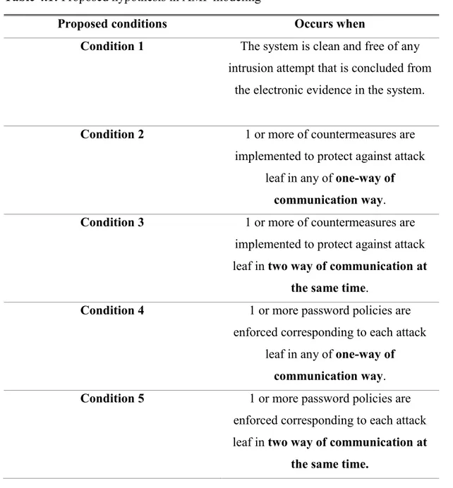
Table 4.1: Proposed hypothesis in AMI modeling
Proposed conditions Occurs when
Condition 1 The system is clean and free of any intrusion attempt that is concluded from
the electronic evidence in the system.
Condition 2 1 or more of countermeasures are implemented to protect against attack
leaf in any of one-way of communication way. Condition 3 1 or more of countermeasures are
implemented to protect against attack leaf in two way of communication at
the same time.
Condition 4 1 or more password policies are enforced corresponding to each attack
leaf in any of one-way of communication way. Condition 5 1 or more password policies are
enforced corresponding to each attack leaf in two way of communication at
the same time.
As described previously in chapter 2.1, while the power is converted between HP to LP in order to accomplish the loads needs, small power stations are needed for feeding process. In similar idea the need for smaller partitions in smart grid systems appear, and those are called microgrids. These microgrids normally designed to derive the required power to loads. So that; it has a limit of power transmitted and received. While designing is processed for these microgrids; steady state conditions are also considered, and it differs according to load types.
27
These steady state conditions considered as the norm one of the system, which represent the clear condition of our system; which is also named as condition 1 as shown in our table.
Figure 4.1: Proposed connection between AMI unites and Smart meters
Figure 4.1 above shows our concerned parts in our study of smart grid systems. Each part uses normally two way of communication with other components. Sensors are fastened over appliance it self and gives information about its consumed or generated power to the smart meter as analog signals which convert it in its turn to digital one and send it to the AMI data center to store it in the memory. Methods that data could be stored are described previously in chapter 2.2. Then AMI unit will make calculations for billing information to be paid to or from the consumer.
So; each part of the system is smart one, which means it has own entire system that is depending over or work. As known for digital systems, there is a firewall for each of them in which it can protect its digital data. As example in smart homes, digital devices are connected to sensors of microwave or freezer or oven, …. Etc; those digital devices are used to monitor the system status and are normally working with android system; which is also has it own firewall for protecting the digital data. Also; for AMI data centers, it consists of servers to store the data, so that firewall is also implemented.
SMART GRID AMI DATA CENTER MICRO GRID AMI DATA CENTER 1 SMART METER 1 sensor 1 SMART METER 2 sensor 2 MICRO GRID AMI DATA CENTER 2 SMART METER 3 sensor 3 SMART METER 4 sensor 4 MICRO GRID AMI DATA CENTER 3 SMART METER 5 sensor 5 SMART METER 6 sensor 6
28
Now, while considering the firewall of the system, between data center and appliance; if data are sent from server to the consumer side; data is transmitted from server (which may has a firewall) to the appliance (which may also has a firewall); this represent a one way communication with one countermeasure applied as a firewall; then it gives us condition 2. If data are transmitted from server to the consumer side, and another data are also delivered to server from the consumer side at the same time; this give us 2 way communication at the same time; thus condition 3 is satisfied.
In same procedure and principle if password policy is applied for one way communication between server and consumer side then condition 4 is satisfied. If it is applied on both way of communication, then condition 5 is also satisfied.
Note: Instead of password policies, human related prints could be used to access the system instead of passwords, such as fingerprints, or eye scan or both of them at the same time.
Depending on the normal distribution principle; the possibility of occurrence for any of above conditions is equal to 1/5 which is 20% for each.
The system could be attacked once it is prepared for work but not yet connected to any loads, i.e it is in the stage of testing it before being completely connected to work in full load to the system; in this stage bugs could be inserted from a hacker in the server to steal consumer billing information or changing the read data in future. In this case condition 1 is satisfied only, because there is no countermeasure or passwords are applied to the system yet; due to it is in the stage before full connection to the load. After that if it is connected, another conditions of 2,3,4, and 5 could be considered; because the system is fully connected now, so that differ conditions could be counted in after.
29
Because there are 5 conditions of possible attack related to each condition, thus the possibility for each one is 0.2 and
ꭙ
will indicate the vulnerability level over all the system or in other word the system condition whether it is vulnerable or not.We will consider
ꭙ
for the smallest leaf in the system between sensor and smart meter, or smart meter and microgrid data center, or microgrid data center and smart grid data center, etc… After that to calculate the system vulnerability completely; all of theseꭙ
’swill be multiplied together as it will be shown later.- If [condition 1 ∩ condition 2 ∩ condition 3 ∩ condition 4 ∩ condition 5 ] are satisfied will give us
ꭙ
= 0.2Here all conditions are satisfied, therefore there is no evidence that the system is subject to malicious attempts. i.e: password and countermeasures are implemented for one way and two way of communications and the system is clean from any previous intrusions.
Note: if [condition 1 ∩ condition 3 ∩ condition 5] are satisfied also;
ꭙ
= 0.2; because countermeasure of two way communication and password application on both of them internally include application on one way communication, thus condition 2 and condition 4 are applied also internally.If any 2 of 5 conditions are satisfied, then
ꭙ
= 2*1/5 = 0.4Table 4.2: Table of probability if 2 conditions are satisfied from proposed hypothesis in this study.
1,1 1,2 1,3 1,4 1,5
2,1 2,2 2,3 2,4 2,5
3,1 3,2 3,3 3,4 3,5
4,1 4,2 4,3 4,4 4,5
5,1 5,2 5,3 5,4 5,5
1: for condition 1, and the systems is clean of vulnerability.
2: for condition 2, countermeasure applied in one way of communication. 3: for condition 3, countermeasure applied for two way communication. 4: for condition 4, password applied in one way of communication. 5: for condition 5, password applied for two way of communication.
30 By eliminating repeated conditions,
1,1 1,2 1,3 1,4 1,5 2,1 2,2 2,3 2,4 2,5 3,1 3,2 3,3 3,4 3,5 4,1 4,2 4,3 4,4 4,5 5,1 5,2 5,3 5,4 5,5 Thus
ꭙ
= 10 / 25 = 0.4This gives indicate that the system is vulnerable by 40%.
- If any 3 of 5 conditions are satisfied, then:
ꭙ
= 3*1/5 = 0.6Table 4.3: Table of probability if 3 conditions are satisfied from proposed hypothesis in this study.
1,1,1 1,1,2 1,1,3 1,1,4 1,1,5 1,2,1 1,2,2 1,2,3 1,2,4 1,2,5 1,3,1 1,3,2 1,3,3 1,3,4 1,3,5 1,4,1 1,4,2 1,4,3 1,4,4 1,4,5 1,5,1 1,5,2 1,5,3 1,5,4 1,5,5 2,1,1 2,1,2 2,1,3 2,1,4 2,1,5 2,2,1 2,2,2 2,2,3 2,2,4 2,2,5 2,3,1 2,3,2 2,3,3 2,3,4 2,3,5 2,4,1 2,4,2 2,4,3 2,4,4 2,4,5 2,5,1 2,5,2 2,5,3 2,5,4 2,5,5 3,1,1 3,1,2 3,1,3 3,1,4 3,1,5 3,2,1 3,2,2 3,2,3 3,2,4 3,2,5 3,3,1 3,3,2 3,3,3 3,3,4 3,3,5 3,4,1 3,4,2 3,4,3 3,4,4 3,4,5 3,5,1 3,5,2 3,5,3 3,5,4 3,5,5 4,1,1 4,1,2 4,1,3 4,1,4 4,1,5 4,2,1 4,2,2 4,2,3 4,2,4 4,2,5 4,3,1 4,3,2 4,3,3 4,3,4 4,3,5
31 4,4,1 4,4,2 4,4,3 4,4,4 4,4,5 4,5,1 4,5,2 4,5,3 4,5,4 4,5,5 5,1,1 5,1,2 5,1,3 5,1,4 5,1,5 5,2,1 5,2,2 5,2,3 5,2,4 5,2,5 5,3,1 5,3,2 5,3,3 5,3,4 5,3,5 5,4,1 5,4,2 5,4,3 5,4,4 5,4,5 5,5,1 5,5,2 5,5,3 5,5,4 5,5,5
Each number of above represents the condition itself. The available conditions that we are going to have are 10 in total. But because the intersection between condition 2 and 3, 4 and 5; then if they came together it will be considered as 3rd condition and 5th condition to be satisfied, because 2 way communication contains 1 way communication internally as described previously. Thus, we will have 1,2,5 / 1,3,4 / 1,3,5 / 2,3,4 /2,4,5 / 3,4,5 which are 6/10.
So that, if 3 conditions are satisfied, the system vulnerability will be by 60%.
- If any 4 of 5 conditions are satisfied then
ꭙ
=0.8. This gives indicate that the system is vulnerable by 80%. In same way that we counted above choices, we can have the result here in same way.- If condition 1 or condition 2 or condition 3 or condition 4 or condition 5 or none of them is met, then
ꭙ
= 1. This indicates that the system is highly vulnerable.To know the overall system attack indices, and after calculating
ꭙ
for every leaf (ꭙ
i)
,the overall will be:
counter = counter + 1 , counter: # of countermeasures or password applied ( 1 ) counter * 0.2 , 2 <= counter <= 4
ꭙ
i = 1 , counter <= 1 ( 2 )0.2 , counter = 5
32
4.3 Proposed Smart grid Cybersecurity Consumer Algorithm
Read AMI and Smart Meter steady state settings
Check if any passwords, eye print, fingerprint is applied for
two way communication
counter = counter + 1
Check if any countermeasure ( Firewall ) is ON for two way
of communication Read AMI and Smart Meter
for actual settings
counter = counter + 1
Compare AMI and Smart Meter settings between Actual and Steady State ones
if they are the same Initialize AMI
and Smart Meter settings
NO
YES Check if any passwords, eye
print, fingerprint is applied for one way communication
Check if any countermeasure ( Firewall ) is ON for one way
of communication counter = counter + 1 counter = counter + 1 NO NO NO YES YES YES NO YES Calculate
ꭙ
from ( 2 ) Ifꭙ
= 1 If 0.2<ꭙ
<= 0.8 Ifꭙ
= 0.2 Re-authorization33
4.4 Simulation of Proposed Smart grid Cybersecurity Consumer Algorithm The simulation process is tested for small leaves or microgrids only. So that; equation (1) and (2) are basically considered. Equation (3) could be easily inserted into the code in later to calculate the overall system vulnerability indices.
To prove that my proposed algorithm can be applied in programmable way, which should be implemented in AMI unites programming, 3 codes had been introduced in Appendix A, B, and C. Knowing that the program is basically used to know the internal process inside AMI unites and smart meters how it could be applied. To display this in easier way; a display function had been written to show the internal status of code running.
First of all, I started the code by clearing any previous value and initialize the simulation program for starting. After that, AMI control unites are directed to read the steady state conditions of its internal settings from internal physical memory and also for smart meters. Then actual readings of those settings are also gathered in order to compare the match between steady state and real readings.
Then the program will send a signal code to the framework of server or system to test if any countermeasure or password policy is applied weather for 1 or 2 way of communication. If any of them is detected, a counter will start increasing; which aims to give us the total number of satisfied conditions in our microgrid system. Then depending on this value, the vulnerability indices is calculated in order to either isolate the system, require a reauthentication again, or to successfully access the financial data.
In each of applied conditions for countermeasures or password polices, values are either 1 or 0, which represent the existing or non-existing status of the condition. On the other hand, steady state and real readings of AMI units and smart meter settings are stored as binary values in memory; because the language which computer can understand is ones and zeros one.
34
Appendix A code is testing the microgrid satisfied conditions, and a graph will be shown up defining the vulnerability indices. By detecting different values; different results are shown up as demonstrated below.
For 5 conditions satisfied and detected by the program the result will be as in figure 4.2.
Figure 4.2: 5 Conditions Satisfied
For 4 conditions satisfied and detected by the program the result will be as in figure 4.3.
35
For 3 conditions satisfied and detected by the program the result will be as in figure 4.4.
Figure 4.4: 3 Conditions Satisfied
For 2 conditions satisfied and detected by the program the result will be as in figure 4.5.
36
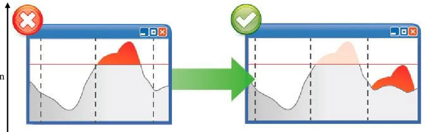
Also; as describe in my previous algorithm, if number of conditions satisfied are either 2, 3, or 4; then a reauthorization for accessing the system will be required as shown below. This message could be transferred to the consumer screen to make a control over the process.
Figure 4.6:Appearing Message if 2,3 or 4 Conditions Satisfied
For 1 condition satisfied and detected by the program the result will be as in figure 4.7.
Figure 4.7: 1 Condition Satisfied
Also; as describe in my previous algorithm, if number of conditions satisfied is 1; then an isolation of the area is required because the system is highly vulnerable. Figure 4.8 shows the related message.
37
Figure 4.8: Appearing Message if 1 Condition Satisfied
Appendix B,C code are testing the microgrid if smart meter and AMI settings are changed or not. If not, the code will work correctly, if yes a message will appear in order to reload the steady state conditions for both and it is automatically loaded internally as shown in figure 4.9.
Figure 4.9: Appearing Message if bugs are inserted or settings between SS and actual readings are not matching
As a result of above simulated cases in different situations; results show that my code is highly flexible and could easily be injected into the framework of the micro systems with zero cost and can detect the vulnerability degree over the system; then to either isolate, reauthorize or to successfully gain for the system process occur. The “protection” part in my code which represents the proposed algorithm is interested in stopping further illegal access for the system in any way or shape it comes in.
So that “ Smart Grid Cyber Protection Algorithm Development “ is satisfied in all of its meanings.
38 5. CONCLUSION AND FUTURE WORK
5.1 Conclusion and Recommendation
As the results show that, implementing defenses methods starting from the consumer side will ensure a higher level of security. On the other hand, two way of communication in smart meters provide the advantage of high response to isolate the risky area, if there is no chance to maintain it remotely. This isolation could be continued until maintenance team arrive to the concerned area. Then they can start by initializing setting of hardware such as AMI unites and smart meters and then load the latest safe information into it. Those information are backed up instantly and could be separated than specific attack starting time.
Table 5.1: Comparison between previous work [12] and my proposed algorithm.
Comparison Topic Previous work My Proposed Work
Type of Grid Smart Grid Smart Grid
Affected layer over network
Network Layer Physical layer Assumed level of attacker
to access information
Skilled attacker Innocent attacker, or skilled one
Concerned attack types DDoS Not specific for only
one, it is general Cost effect May need upgrading server
in which data are stored. ( for framework upgrade )
No need for any changes, only
inserting the algorithm or the
code in a programmable way
for any framework generation will take
39 5.2 Future work
This paper could be used in developing other security ways, such as the use of firewalls, control the access for the network, and limitation of accessible data, to prevent cyber-attack over smart grid systems.
Also it could be used to develop the proposed algorithm in my study to enhance the security of the smart systems and to propose another algorithm which could be used on the communication channel between AMI’s unites themselves or between several microgrid data centers. So that; those algorithms on both sides of communication channel can communicate in between and work simultaneously.
40 REFERENCES
[1] B. A. Hamilton and J. Miller , "Smart Grid Implementation Strategy," in Understanding the Benefits of the Smart Grid , National Energy Technology Laboratory, 2010, pp. 1-33.
[2] Y. Kabalci, "A survey on smart metering and smart grid communication," Renewable and Sustainable Energy Reviews, vol. 57, no. ELSEVIER, pp. 302-318, 2016.
[3] P. C. Jain, "Trends in smart power grid communication and networking," in International Conference on Signal Processing and Communication (ICSC), Noida, India, 2015, pp 374-379.
[4] P. Umang and M. Mitul, "A Review on Smart Meter System," INTERNATIONAL JOURNAL OF INNOVATIVE RESEARCH IN
ELECTRICAL, ELECTRONICS, INSTRUMENTATION AND CONTROL ENGINEERING, vol. 3, no. 12, pp. 70-73, December 2015.
[5] Q. Sun, H. Li, Z. Ma, C. Wang, J. Campillo, Q. Zhang, F. Wallin and J. Guo, "A Comprehensive Review of Smart Energy Meters in Intelligent Energy Networks," IEEE INTERNET OF THINGS JOURNAL, vol. 3, no. 4, pp. 464-479, AUGUST 2016.
[6] S. N. Kulkarni and P. Shingare, "A review on Smart Grid Architecture and Implementation Challenges," in International Conference on Electrical, Electronics, and Optimization Techniques (ICEEOT), 2016, P 3288.
[7] E. N. YILMAZ, H. POLAT, S. OYUCU, A. AKSOZ and A. SAYGIN, "Data Storage in Smart Grid Systems," in 6th International Istanbul Smart Grids and Cities Congress and Fair (ICSG), Istanbul , 2018, P 110-113.
[8] Z. ZHANG , h. LIU , S. NIU and J. MO , "Information Security Requirements and Challenges in Smart Grid," 2011 6th IEEE Joint International Information Technology and Artificial Intelligence Conference, vol. 2011, no. Chongqing, pp. 90-92, 2011.
[9] C. W. Ten, G. Manimaran and C. C. Liu, "Cybersecurity for Critical
Infrastructures: Attack and Defense Modeling," IEEE TRANSACTIONS ON SYSTEMS, MAN, AND CYBERNETICS—PART A: SYSTEMS AND HUMANS, vol. 40, no. NO. 4, pp. 853-865, JULY 2010.
[10] "International Organization for Standardization," ISO, 06 2005. [Online]. Available: https://www.iso.org/standard/39612.html.
41
[11] A. Stefanov and C. C. Liu, "Cyber-Power System Security in Smart Grid Environment," Science Foundation Ireland (SFI), Dublin, 2011.
[12] R. Diovu and J. Agee, "A CLOUD-BASED OPENFLOW FIREWALL FOR MITIGATION AGAINST DDoS ATTACKS IN SMART GRIDAMI
NETWORKS.," in 2017 IEEE PES PowerAfrica, Accra, Ghana, 27-30 June 2017.
[13] X. Liu, P. Zhu, Y. Zhang and K. Chen, "A Collaborative Intrusion Detection Mechanism Against False Data Injection Attack in Advanced Metering
Infrastructure," IEEE TRANSACTIONS ON SMART GRID, vol. 6, no. 5, pp. 2435-2443, SEPTEMBER 2015.
[14] Mavridou, Anastasia & Papa and Mauricio, "A Situational Awareness Architecture for the Smart Grid," H. Jahankhani et al. (Eds.): ICGS3/e-Democracy, vol. LNICST 99, no. 2011, pp. 229-236, 2012.
[15] Fang, Xi & Misra, Satyajayant & Xue and Guoliang & Ya, "Smart Grid — The New and Improved Power Grid: A Survey. Communications Surveys &
Tutorials," IEEE COMMUNICATIONS SURVEYS & TUTORIALS,, vol. 14, no. 4, pp. 944-980, 2012.
42 APPENDICES
Appendix A : Proposed Simulation Code Using MATLAB – Number of Conditions Satisfied
Appendix B : Proposed Simulation Code Using MATLAB – Smart Meter Steady State Settings Not Satisfied
Appendix C : Proposed Simulation Code Using MATLAB – AMI Steady State Conditions Not Satisfied
44 APPENDIX A :
Proposed Simulation Code Using MATLAB – Number of Conditions Satisfied
clc clear
AMI_ss= load('AMI_ss.txt'); % Define AMI steady state situation - reset
s_m_ss= load('s_m_initial.txt'); % Define smart grid steady state situation - reset
onewaypass=load('onewaypass.txt'); % Define one way communication password as ON OFF values
twowaypass=load('twowaypass.txt'); % Define two way communication password as ON OFF values
onewaycmeasure=load('onewaycm.txt'); % Define one way communication countermeasure such as firewall as ON OFF values
twowaycmeasure=load('twowaycm.txt'); % Define two way communication countermeasure such as firewall as ON OFF values
s_m1=load('s_m1.txt'); % assuming this value for true smart meter settings
s_m2=load('s_m2.txt');% assuming this value for false smart meter settings
AMI_1=load('AMI_1.txt'); % assuming this value for true AMI settings
AMI_2=load('AMI_2.txt');% assuming this value for false AMI settings
c=0; % counter initializing if AMI_ss==AMI_1 if s_m_ss == s_m1 c=c+1 end if twowaypass==1 c=c+1 end if onewaypass==1 c=c+1 end if twowaycmeasure==1 c=c+1 end if onewaycmeasure==1 c=c+1 end if c == 5 x=0.2 end if c==1 x=1
45
end
if c==2 x=c*(1/5)
ra='Reauthorization Required'
disp(ra)
elseif c==3
x=c*(1/5)
ra='Reauthorization Required'
disp(ra)
elseif c==4
x=c*(1/5)
ra='Reauthorization Required'
disp(ra) end
bar(c,x,0.1)
title('Different Conditions & Countermeasures Applied to Calculate
Leaf Indices')
xlabel('Number of Satisfied Conditions') ylabel('One Small Leaf Indices Value') axis([0 5 0 1])
set(gca,'xtick',[1 2 3 4 5])
else
AMI_ss= load('AMI_ss.txt'); % reload of AMI steady state rl='Steady State Conditions Relode Required'
disp(rl)
46 APPENDIX B :
Proposed Simulation Code Using MATLAB – Smart Meter Steady State Settings Not Satisfied
clc clear
AMI_ss= load('AMI_ss.txt'); % Define AMI steady state situation - reset
s_m_ss= load('s_m_initial.txt'); % Define smart grid steady state situation - reset
onewaypass=load('onewaypass.txt'); % Define one way communication password as ON OFF values
twowaypass=load('twowaypass.txt'); % Define two way communication password as ON OFF values
onewaycmeasure=load('onewaycm.txt'); % Define one way communication countermeasure such as firewall as ON OFF values
twowaycmeasure=load('twowaycm.txt'); % Define two way communication countermeasure such as firewall as ON OFF values
s_m1=load('s_m1.txt'); % assuming this value for true smart meter settings
s_m2=load('s_m2.txt');% assuming this value for false smart meter settings
AMI_1=load('AMI_1.txt'); % assuming this value for true AMI settings
AMI_2=load('AMI_2.txt');% assuming this value for false AMI settings
c=0; % counter initializing if AMI_ss==AMI_1 if s_m_ss == s_m2 c=c+1 end if twowaypass==1 c=c+1 end if onewaypass==1 c=c+1 end if twowaycmeasure==1 c=c+1 end if onewaycmeasure==1 c=c+1 end if c == 5 x=0.2 end if c==1 x=1
47
is='Area isolated'
disp(is) end
if c==2 x=c*(1/5)
ra='Reauthorization Required'
disp(ra)
elseif c==3
x=c*(1/5)
ra='Reauthorization Required'
disp(ra)
elseif c==4
x=c*(1/5)
ra='Reauthorization Required'
disp(ra) end
bar(c,x,0.1)
title('Different Conditions & Countermeasures Applied to Calculate
Leaf Indices')
xlabel('Number of Satisfied Conditions') ylabel('One Small Leaf Indices Value') axis([0 5 0 1])
set(gca,'xtick',[1 2 3 4 5])
else
AMI_ss= load('AMI_ss.txt'); % reload of AMI steady state rl='Steady State Conditions Relode Required'
disp(rl)
48 APPENDIX C :
Proposed Simulation Code Using MATLAB – AMI Steady State Conditions Not Satisfied
clc clear
AMI_ss= load('AMI_ss.txt'); % Define AMI steady state situation - reset
s_m_ss= load('s_m_initial.txt'); % Define smart grid steady state situation - reset
onewaypass=load('onewaypass.txt'); % Define one way communication password as ON OFF values
twowaypass=load('twowaypass.txt'); % Define two way communication password as ON OFF values
onewaycmeasure=load('onewaycm.txt'); % Define one way communication countermeasure such as firewall as ON OFF values
twowaycmeasure=load('twowaycm.txt'); % Define two way communication countermeasure such as firewall as ON OFF values
s_m1=load('s_m1.txt'); % assuming this value for true smart meter settings
s_m2=load('s_m2.txt');% assuming this value for false smart meter settings
AMI_1=load('AMI_1.txt'); % assuming this value for true AMI settings
AMI_2=load('AMI_2.txt');% assuming this value for false AMI settings c=0; % counter initializing if AMI_ss==AMI_2 if s_m_ss == s_m1 c=c+1 end if twowaypass==1 c=c+1 end if onewaypass==1 c=c+1 end if twowaycmeasure==1 c=c+1 end if onewaycmeasure==1 c=c+1 end if c == 5 x=0.2 end
49
if c==1 x=1
is='Area isolated'
disp(is) end
if c==2 x=c*(1/5)
ra='Reauthorization Required'
disp(ra) elseif c==3 x=c*(1/5)
ra='Reauthorization Required'
disp(ra) elseif c==4 x=c*(1/5)
ra='Reauthorization Required'
disp(ra) end
bar(c,x,0.1)
title('Different Conditions & Countermeasures Applied to
Calculate Leaf Indices')
xlabel('Number of Satisfied Conditions') ylabel('One Small Leaf Indices Value') axis([0 5 0 1])
set(gca,'xtick',[1 2 3 4 5])
else
AMI_ss= load('AMI_ss.txt'); % reload of AMI steady state
rl='Steady State Conditions Relode Required'
disp(rl) end
50
Resume
Name Surname: Ahmet DURMUŞ
Place and Date of Birth: Amman/Ürdün 31.05.1993 E-mail: [email protected]
Education
:• Bachelor : 2016, The Hashemite University, Faculty of Engineering, Electrical Engineering
• Master : 2019, İstanbul Aydın University, Faculty of Science and Technology, Electrical and Electronics Engineering
Professional Experiance:
• Imtilak Emlak Insaat Turizm Çeviri Pazarlama Ve Dis Tic. Ltd. Şti ( 03.2018 – 08.2019 )
03.2019 - 08.2019 : Department Manager
03.2018 – 03.2019 : Sales Representative, Social Media and Marketing • Şafak İş Makinalari Eğitim Hiz. Ltd. Şti. ( 01.2016 - 08.2017 )
- Electrical Engineering Instructor in Renewable Energies and Smart Grid Systems. - IT Department Supervision.
![Figure 1.2:smart grid perspective with all components [2]](https://thumb-eu.123doks.com/thumbv2/9libnet/4197872.65177/28.892.105.726.185.615/figure-smart-grid-perspective-components.webp)
![Figure 1.3: Smart meters [2]](https://thumb-eu.123doks.com/thumbv2/9libnet/4197872.65177/29.892.224.482.167.533/figure-smart-meters.webp)
![Figure 1.4: Power generation,control,and measurement diagram [2]](https://thumb-eu.123doks.com/thumbv2/9libnet/4197872.65177/30.892.161.726.105.538/figure-power-generation-control-measurement-diagram.webp)
![Figure 1.5: Smart Grid Infrastructure [6]](https://thumb-eu.123doks.com/thumbv2/9libnet/4197872.65177/31.892.260.752.288.756/figure-smart-grid-infrastructure.webp)
![Figure 3.1: RAIM Framework [9]](https://thumb-eu.123doks.com/thumbv2/9libnet/4197872.65177/39.892.143.821.178.618/figure-raim-framework.webp)
![Figure 3.2: Algorithm to evaluate vulnerability indices [9]](https://thumb-eu.123doks.com/thumbv2/9libnet/4197872.65177/42.892.243.587.254.658/figure-algorithm-evaluate-vulnerability-indices.webp)
![Figure 3.3: Attack tree of normal power system control framework [9]](https://thumb-eu.123doks.com/thumbv2/9libnet/4197872.65177/43.892.173.858.442.720/figure-attack-tree-normal-power-control-framework.webp)