http://dx.doi.org/10.1007/s12555-016-0132-5 http://www.springer.com/12555
Disturbance Attenuation in Linear Systems Revisited
Jiqiang Wang*, Hong Yue, and Georgi Dimirovski
Abstract:A variety of methods have been proposed for attenuating or rejecting disturbances in linear systems. Most of the approaches, however, are targeting the performance either near resonance or across the whole fre-quency range. Weighting functions can be utilized to shape the frefre-quency response function over target frefre-quency band but they are usually of rule-of-thumb nature. A methodology is necessitated for designing controllers with performance specified at any discrete frequency or over any desired frequency band. The paper aims to develop such a methodology. Besides this, the proposed method can tell performance limitations and determine the prob-lem of existence of optimal controllers, as well as providing a useful framework to improve the performance of an existing controller. A number of important results are obtained and these results are subsequently validated through a practical application to a rotor blade example.
Keywords:Discrete frequency control, disturbance attenuation, linear systems, performance limitation & improve-ment.
1. INTRODUCTION
Disturbance attenuation/rejection represents one of the most important problems in control system design. Con-ventional approach to disturbance attenuation is the classi-cal sensitivity shaping that eventually cultivates into a uni-fied regulator theory in a generalized plant setup [1–3]. In this setup, the disturbance attenuation concerns the prob-lem of minimizing the gain (usually in H2/H∞ norm) from disturbance input to regulated output [4,5]. The
H2/H∞ optimization methodology is powerful since it
can also handle constraints by formulating into LMIs [6]. Indeed, within this framework, there exists numerous lit-erature on tackling the disturbance attenuation problem (subject to uncertainty, saturation, delay etc), e.g., via state feedback, dynamic feedback, eigenstructure assignment, adaptive controls etc. In fact, this H2/H∞ optimization methodology to disturbance attenuation has been extended into nonlinear systems [7,8], discrete event and multi-agent systems [9,10], hybrid dynamical systems [11–13] and networked control systems [14–16] etc.
The above methodology, however, aims to achieve min-imization of H2/H∞ norm over all frequencies. Typi-cal filter design exists for shaping/weighting the frequency range of interest, e.g., the H∞ optimization tries to “bring down” the peak magnitude of the frequency response function, but it is not transparent for the design
method-Manuscript received March 7, 2016; revised October 28, 2016; accepted December 4, 2016. Recommended by Associate Editor Young Ik Son under the direction of Editor Duk-Sun Shim. This work is supported by the Natural Science Foundation of Jiangsu Province (No. BK20140829); and the Fundamental Research Funds for the Central Universities (No. NS2016024).
Jiqiang Wang is with Jiangsu Province Key Laboratory of Aerospace Power Systems, College of Energy and Power Engineering, Nanjing University of Aeronautics and Astronautics, China (e-mail: [email protected]). Hong Yue is with the Department of Electronic & Electrical Engineering, University of Strathclyde, UK (e-mail: [email protected]). Georgi Dimirovski is with the Dogus University of Istanbul, Istanbul 34722, Turkey (e-mail: [email protected]).
* Corresponding author.
ology on how to shape the performance over a frequency band[ ω1 ωN
]
, while allowing performance deteriora-tion outside[ ω1 ωN
] .
While H2/H∞ optimization methodology to distur-bance attenuation arises from control community, there are different approaches coming from noise and vibra-tion control community. In this field, disturbance atten-uation is mainly handled through internal model princi-ple and adaptive disturbance estimation (see the review article [17]). The performance index is usually defined as of a minimum variance type (with weightings), which is essentially equivalent to minimizing a weighted mean square error [18–20]. Henceforth, the approaches are not targeting the performance defined over a frequency band. Even though the minimum variance type of square errors is defined at narrow band frequencies, simply synthesiz-ing an optimal controller ussynthesiz-ing optimal control method-ology does not provide information on important prob-lems such as the limit of performance at the desired fre-quency. In fact, the problem of determining limit of per-formance is an important issue that has unfortunately over-looked for many design approaches. The mixed sensitiv-ity method takes care of this issue by minimizing H2/H∞ norm for both sensitivity S and complementary sensitivity
T [21,22]. But the choice of weighting functions for both
S and T is of rule-of-thumb nature, aiming to maintain the
ideal shapes for the norms of sensitivity functions (e.g., S
c
small in low frequencies and T small over high frequen-cies etc). Important intuition on both solution existence and limit of performance at any discrete frequencyω0or
over a frequency band[ ω1 ωN ]
is thus lost.
The above mentioned methods represent a class of pas-sive approach to disturbance attenuation in that distur-bance is handled through tolerating the worst case sce-nario. There exists a class of active approach that inten-tionally estimates and tackles the disturbance in real time. These are disturbance observer-based methods which also include many forms of disturbance observers [23–25]. Yet another active approach is control reconfiguration where either scheduled or online computation strategy is deployed to actively compensate the detrimental effects caused by faults or exogenous disturbances, please refer to [26,27] for a review.
However, for both passive and active approaches, dis-turbance attenuation is handled either over all frequency bands or in a narrow band through (notch) filters. And the problem of disturbance attenuation within a prescribed frequency band has not been given detailed investigation. Therefore, for disturbance attenuation, a methodology is necessitated that can possess the following features and capabilities simultaneously:
1) Allow disturbance attenuation at any specific fre-quency or over any desired frefre-quency band;
2) Allow explicit determination of performance limitation for any frequency or over any desired frequency band; 3) Allow performance improvement to current control.
In specific, feature 1) will provide a systematic sensitiv-ity shaping method other than using weighting functions; feature 2) is even important, since prior to control design, a series of significant questions can be resolved, such as: 1) Does a controller exist that suppresses disturbance in both S and T , and by how much (in dB)? 2) Does a con-troller exist that will annihilate S without enhancement of
T ? And similarly 3) Does a controller exist that will
an-nihilate T without enhancement of S? Also 4) Can a con-troller be found that will suppress S whenever T is attenu-ated, and vise versa?
Feature 3) will be extremely important for the situation where the disturbance is known to be in a specific fre-quency band (but not necessarily being able to be mod-eled or even measurable). Then the proposed method can be utilized to further enhance the controller performance over the desired frequency band, while accepting perfor-mance deterioration outside that frequency band (due to Bode’s integral relationships or waterbed effect). In fact, no control design methodology is capable of exploiting performance limitation over a specific and explicit fre-quency band, but it can be demonstrated that the proposed method can always improve the current control design, be it H2/H∞, PID, or adaptive control etc over an explicitly
defined frequency band [ ω1 ωN ]
. In this sense, the proposed method is claimed to be UNIVERSAL to perfor-mance improvement at any discrete frequency or over any desired frequency band. The above features form the con-tribution of the current paper. They will be explained in the following sections: Section 2 formulates the problem; Section 3 and Section 4 consider the discrete frequency control and broad band control respectively; the above the-oretical results are validated through their application to a rotor blade structure in Section 5, while a comparative study with optimal control design is carried out in Section 6. Finally, Section 7 concludes the paper.
2. PROBLEM FORMIULATION
To fix the discussion, the systems dynamics is described by the following frequency response functions:
y( jω) z1( jω) z2( jω) .. . zn( jω) = G00( jω) G01( jω) ··· G0n( jω) G10( jω) G11( jω) ··· G1n( jω) .. . ... . .. ... Gn0( jω) Gn1( jω) ··· Gnn( jω) × u( jω) w1( jω) w2( jω) .. . wn( jω) . (1)
In the above equation, u( jω) represents control in-put and wi( jω) the ith exogenous disturbance. y( jω) is the available feedback variable and zi( jω) are the per-formance variables to be controlled but unavailable for feedback. The design objective is therefore to use only
the feedback action u( jω) = K( jω)y( jω)for simultane-ous disturbance attenuation in both y( jω)and zi( jω)for
i = 1, ..., n.
To simplify the problem at discussion, it is further as-sumed that the exogenous disturbances wi( jω)s can be ex-pressed as wi( jω) = Cid( jω) for a frequencyωand Ciis a complex number representing the gain and phase shift with respect to the same exogenous signal d( jω). Then (1) can be rewritten as follows, dropping off the depen-dence on frequency for easy reference:
y z1 z2 .. . zn = G00 G01 ··· G0n G10 G11 ··· G1n .. . ... . .. ... Gn0 Gn1 ··· Gnn u C1d C2d .. . Cnd . (2)
Then with the only available feedback control u = Ky the performance response y to exogenous signal d is given:
Tyd= (1− G00K)−1
n
∑
k=1G0kCk. (3)
The performance response of zito d is:
Tzid= [ 1 +Gi0K(1− G00K) −1∑n k=1G0kCk ∑n k=1GikCk ] ×
∑
n k=1 GikCk. (4)The design objective can therefore be formulated as finding a controller K such that Tyd and Tzid (= 1, ..., n)
are attenuated for a frequencyω0or over a frequency band
[
ω1 ωN ]
. Clearly, to address this problem, the follow-ing questions must be resolved:
1) The feasibility of simultaneous attenuation in both
y( jω) and zi( jω) using only control u = Ky;
2) The level of attenuation in both y( jω) and zi( jω)s wherever simultaneous attenuation is possible; 3) Given a performance specification (e.g., attenuate
y( jω) by 6 dB while all zi( jω)s at least 3 dB etc), synthesize an optimal controller K( jω) to fulfill the performance;
4) Robustness issues associated with the optimal design. The first question is of fundamental importance since answering existence questions is an important component of a good design methodology. However, an optimal con-troller should ultimately be produced. These problems are handled in the following sections.
3. DISCRETE FREQUENCY CONTROLLER
DESIGN
To proceed, first consider the situation at a discrete fre-quencyω0. Thus to attenuate the disturbance in y( jω0),
the feedback sensitivity S≡ (1 − G00K)−1 must be
sup-pressed; similarly, disturbance in zican be attenuated, pro-vided that the disturbance response ratio for all zi( jω0)s
must be suppressed simultaneously. That is:
|S( jω0)| < 1, (5) |Ri( jω0)| < 1∀i = 1,··· ,n, (6) where Ri= 1 + Gi0 n
∑
k=1 G0kCk G00 n∑
k=1 GikCk (S− 1) . (7)Remark 1: The performance response of y to d in (3), and zi to d in (4) can now be expressed as: Tyd =
S∑nk=1G0kCkand Tzid= Ri∑
n
k=1GikCk, hence S and Riare the ratio of the closed-loop to the open-loop response with respect to the exogenous input wi(not d). Thus the origi-nal design objective can be reformulated as finding a con-troller K such that the conditions (5) and (6) hold simul-taneously for a frequency ω0 or over a frequency band
[
ω1 ωN ]
.
Remark 2:For discrete frequency control, either adap-tive estimations (feedforward or feedback) or notch filters are used for suppressing the harmonic disturbance atω0in
the field of noise and vibration control. These approaches are effective but will lose intuition into solution existence and limit of performance.
In the following, a pictorial method is developed to de-termine if a controller K exists that satisfies conditions (5) and (6) simultaneously. The key to solve this problem is to notice that at a discrete frequencyω0, S and all Ris are
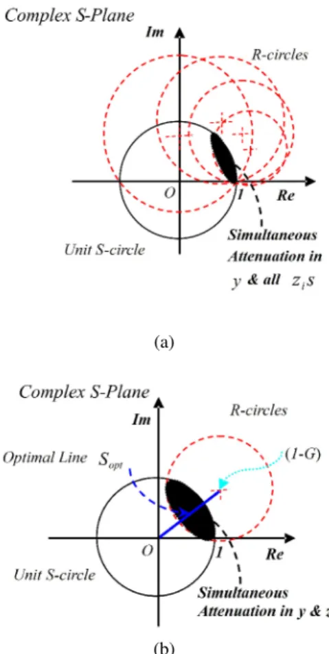
simply complex numbers. Therefore, (6) can be mapped onto the complex S-plane in (5) through the Möbius trans-formation defined by (7). The result of the mapping is n circles (call them R-circles) with circle-i having centre
(1-real(G), -imag(Gi)) and radius |Gi|, where Gi is defined as: Gi= G00 n
∑
k=1 GikCk Gi0 n∑
k=1 G0kCk for i = 1, ..., n. (8)This situation is illustrated in Fig. 1. It is noted that all the R-circles intersect unit S-circle at point (1, 0). At this point, S = Ri= 1∀ i = 1, ..., n. This implies that the performance responses of y and zis are simply their open
loop responses and the controller K = 0. For any other points, the levels of attenuation in y and ziare the scaling with respect to the unit S-circle and R-circle, respectively. For example, for a point with Cartesian coordinate (a, b), the attenuation or enhancement in y and zi (closed loop performance) is√a2+ b2and
√
[a+real(Gi)−1]2+[b+imag(Gi)]2
|Gi|
depending on values being smaller or greater than unity. Fig. 1(b) shows the situation for each Ri-circle. It is seen that an optimal line connecting the origins of the two circles can be naturally defined: at the origin of S-circle, disturbance at y( jω0) is annihilated while disturbance at
zi( jω0) is completely rejected at the origin of Ri-circle;
moving the point on the optimal line results in a com-promise in the level of attenuation in between y( jω0) and
zi( jω0). Thus the following important results follow from
the inspection of Fig. 1:
Proposition 1 (Feasibility of Simultaneous Reduc-tion): Simultaneous attenuation in y( jω) and all zi( jω)
∀ i = 1, ..., n for a frequencyω0 is feasible if and only if
there exists intersection among all the R-circles and unit
S-circle.
(a)
(b)
Fig. 1.Geometry of S and R revealing fundamental per-formance limitation at a discrete frequency.
The level of reduction in y( jω) and zi( jω) for a frequency ω0is determined by the scaling with respect to the unit
S-circle and Ri-circles, respectively.
Proposition 2 can be further delineated leading to a se-ries of important results:
Result 1: A controller exists that provides infinite re-duction in zi( jω0) without any enhancement in y( jω0)
if and only if the centre (1-Gi) locates inside the unit
S-circle.
Result 2: A controller exists that provides infinite re-duction in y( jω0) without any enhancement in zi( jω0) if
and only if the origin of the unit S-circle locates inside the
mapped Ri-circle.
Result 3: A controller exists that will reduce one when-ever the other is reduced if and only if Gi=1. In this case, the mapped Ri-circle coincides with the unit S-circle, and hence y( jω0) and zi( jω0) are also attenuated by the same
amount.
Now choosing a particular point on the complex
S-plane implies designating a particular value for the
sensi-tivity S( jω) and this consequently means a particular de-sign K( jω) is obtained. This is the optimal controller for the discrete frequency control.
Proposition 3 (Optimal Controller Synthesis): The optimal controller K( jω) achieving the performance spec-ified by the optimal choice S( jω) can be obtained as fol-lows:
K( jω) = S( jω)− 1
S( jω)G00( jω)
. (9)
Remark 3:Except at the special case S( jω) = 0 mean-ing annihilation in y( jω), which is impractical due to the requirement for infinite gain, the controller in (9) can be easily implemented at any discrete frequency using a re-cursive algorithm estimating the gain and phase shift of the harmonic signal. Also, from Fig. 1(b), it remains to see that a robust optimal controller exists at the middle of the optimal line Sopt, should the simultaneous attenuation in both y( jω0) and zi( jω0) be required.
The above results are of great practical importance since they suggest a method of resolving Higher Harmon-ics Control (HHC) that has been challenging in vibration and noise control problems. In the HHC problem, the disturbance is dominated by a discrete set of frequencies with higher harmonics often causing spillovers. To han-dle this problem, control is designed for each harmonic of the disturbance (superposition principle is applied). Thus the number of controllers required is increased with the increasing number of harmonics to be controlled. How-ever, the results above suggest a distinctive solution to this problem.
Proposition 4 (HHC Problem): If there exists inter-section among the R-circles of the higher harmonics to be controlled, then all the higher harmonics can be controlled by a single controller; if this intersection further intersects the unit S-circle, then this single controller will provide simultaneous reduction in all the performance variables.
Remark 4: This result is remarkable since it can be used to reduce the number of controllers for the HHC problem. This can substantially reduce the complexity and cost associated with the implementation of the control sys-tem.
4. BROAD BAND CONTROL & PERFORMANCE
IMPROVEMENT
With the fundamental results for discrete frequency control, the problem of finding a controller K such that the conditions (5) and (6) hold simultaneously over a fre-quency band[ ω1 ωN
]
can be resolved. But it is to be seen that this is a much involving problem since closed loop stability has to be concerned. It is also noted that the optimal choice S( jω) is to be varied from one frequency to the other over the target frequency band. This results in an optimal trajectory on the complex S-plane. However a further constraint should be put on the design freedom
S( jω) so that closed loop stability is ensured. This can be approached by defining Ω( jω) = S( jω)− 1, then it can
be proved ifΩ( jω) is a mapping of a stable function that also interpolates the unstable zeros of G00(s), then the
re-sulting controller will internally stabilize the closed loop system for a stable but non-minimum phase G00(s). For
a stable and minimum phase plant, the only constraint on the trajectory ofΩ( jω) will be simply a mapping of a sta-ble function. That is, ifΩ( jω) is a mapping of a stable function, then the resulting compensator will internally stabilize the closed loop system for a stable and minimum phase G00(s).
However it is a well-known result that a stabilizing con-troller can itself be unstable. In practice, it will be desir-able to have a stdesir-able and stabilizing controller, e.g., if the feedback loop opens due to sensor or actuator failure, an unstable controller can become problematic. The follow-ing main result solves this strong stabilization problem.
Proposition 5: If G00(s) is both stable and minimum
phase andΩopt( jω) is a mapping of a stable function and, in addition, Re(Ωopt) >−1 when Im(Ωopt) = 0, then the resulting controller will not only internally stabilize the closed loop system and but also be itself stable.
Proof: It is first noted that the loop gain can be de-scribed by:
L( jω) = K( jω)G00( jω) = Ω( jω
)
1 +Ω( jω). (10) The expression is equivalent to a closed loop system with loop gainΩ( jω), thus L will be stable ifΩ( jω) is also stable and its mapping of the Nyquist D-contour does not enclose the (−1,0) point on the complex plane. Both of the stability conditions can simultaneously be met by ensuring that theΩ( jω)always crosses the real axis to the right of the (−1,0) point. If now G00(s) is stable and
min-imum phase, then for a stable L, K(s) will be stable and there will be no unstable pole-zero cancellations between
G00(s) and K(s). This completes the proof. □
Remark 5: The assumption that G00(s) is both stable
and minimum phase is not unduly restrictive since it is very likely that the sensor and actuator can be arranged to be collocated. As a consequence, a stable and minimum phase of G00(s) can be achieved. But it will be also
re-minded that the controller realization algorithm to be de-veloped below can be used to account for a non-minimum phase G00(s).
Now the optimal controller still needs to be con-structed from the optimal choise S( jω) over the fre-quency band [ ω1 ωN
]
. From Proposition 5, this is essentially a problem of finding a stable transfer function Ω(s) that interpolates the data points defined by Ω( jω) over [ ω1 ωN
]
. This turns out to be a generalized Nevanlinna-Pick interpolation problem whose answer is provided by a modifed Pick condition [28]:
Modifed Pick Condition for Stable Interpolation:A stable transfer functionΩ(s) that interpolates the optimal
choice defined by Ωopt( jω) over [ ω1 ωN ]
exists if and only if the Pick matrix P is positive definite:
P = [ 1− ΩkΩl/M2 j(ωk−ωl) + 2a ] 1≤k, l≤N ,
whereΩiis the optimal choiceΩopt( jωi) for frequencyωi
∀ i ∈ [1,N]; a and M are positive real numbers defining
the minimal degree of stability and maximum modulus of Ω(s) on the half plane ℜ(s) ≥ −a.
However, that P fails to be positive definite would im-ply that the desired transfer functionΩ(s) does not exist. The best approximation to the optimal data points must be found. This can be achieved through a series of linear ma-trix inequalities (LMIs), with some of which defines the uncertainty bounded around each data points Ωopt( jωi) for frequency ωi over the frequency band
[
ω1 ωN ]
. By gradually relaxing the uncertainty bound, the best ap-proximation to the optimal data points will be eventually obtained. Experiences show that the resulting loss of per-formance is marginal, and thus there is not much con-servatism associated with the design. The desired stable transfer function Ω(s) that best interpolates the optimal choice is then obtained for either transfer function or state-space representation [29]. Manipulating (9) leads to the optimal controller K(s) = [1+Ω(s)]GΩ(s)
00(s).
Remark 6: It is noted that the above optimal con-troller will be guaranteed to provide best approximation to the performance specified in both y( jω) and zi( jω)s over the frequency band [ ω1 ωN
]
. Conventionally, this problem is to be formulated as a mixed sensitivity
problem such as Ws(s)S( jω) W1(s)R1( jω) .. . Wn(s)Rn( jω) ∞ ≤γ. While there exist rule-of-thumbs to choose the weighting functions to shape the sensitivities, it is still difficult to specify the per-formance or exploit perper-formance limitations over any fre-quency band, nevertheless to tell if a performance specifi-cation in sensitivities is feasible or not.
Remark 7: It remains to see that the above proce-dure for optimal controller synthesis is a universal method to performance improvement to current control design, be it H2/H∞ or PID, over any desired frequency band [
ω1 ωN ]
. This is achieved by utilizing the data points generated by current control, and the proposed method is then utilized to exploit the limit of performance for best achievable specification. The resulting controller will improve the performance over the frequency band [
ω1 ωN ]
while scarifying performance outside that frequency band (due to Bode’s integral relationship). If the to-be-rejected disturbance is known to be in a specific frequency band, the proposed method will be beneficiary and certainly of significance to many practical systems.
attenuation design methodology are summarized as fol-lows:
Design Procedures for Discrete Frequency Control Step 1: From the system plant, determine the geometry of S and R;
Step 2: Depending on design objective, choose appro-priate S( jω) point from the Tradeoff Line (Fig. 1);
Step 3: Implement the feedback controller K( jω) as in (9).
Design Procedures for Broad Band Control
Step 1: From the system plant, determine the geometry of S and R;
Step 2: Depending on design objective, choose appro-priate S( jω) points over[ ω1 ωN
]
(optimal choices on complex S-plane);
Step 3: Find a stable functionΩ(s) such that it interpo-lates the optimal trajectoryΩ( jω) = S( jω)− 1 designed in Step 2;
Step 4: Implement the feedback controller as K(s) =
Ω(s) [1+Ω(s)]G00(s).
5. DISTURBANCE ATTENUATION FOR A
ROTOR BLADE STRUCTURE: DISCRETE FREQUENCY CONTROL
In this section, a practical example is provided for dis-crete frequency control. Consider a rotor blade struc-ture where disturbance enters through blades propagating along the shaft, the system is represented in (11) and the scenario is that only feedback control u = Ky is available to control both y and z at a frequencyω. u represents the force applied at the base of the rotor shaft, y is the accel-eration at the base of the shaft and z is the accelaccel-eration on the rotor blade.
[ y( jω) z( jω) ] = [ G00( jω) G01( jω) G10( jω) G11( jω) ][ u( jω) d( jω) ] . (11)
Fig. 2(a) shows the measured frequency response of the blade acceleration to excitation of the blade (the plot is hence of|G11( jω)| ). The first bending mode resonance
in the region of 244 Hz clearly leads to a peak in the trans-mission along the shaft as shown in the measured base response|G01( jω)| in Fig. 2(b).
Now map the R-circle onto the complex S-plane through the Möbius transformation defined by (7) atω= 244 Hz. The resulting geometry of R and S is shown in Fig. 3. Also shown (dotted circles) are the mappings that represent a 6 dB attenuation boundary for y and z, respectively.
Feasibility of Simultaneous Reduction: From Fig. 3, it is seen that there is a significant area of intersection be-tween the unit S-circle and R-circle. And it follows from Proposition 1 that simultaneous attenuation in y( jω) and
z( jω) forω= 244 Hz is feasible.
Level of Reduction and Optimal Control Design: Now choose 3 points labelled A, B and C in Fig. 3 and
(a)
(b)
Fig. 2.(a) blade response to blade excitation (|G11( jω)|),
(b) Base response to blade excitation (|G01( jω)|).
construct the corresponding controller respectively. Since point A lies on the boundary of the unit S-circle and well within the 6dB boundary of the R-circle, Proposition 2 shows that the resulting optimal controller will leave
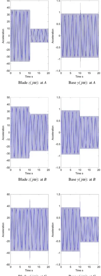
y( jω) unchanged while reducing z( jω) by a little over 11dB; conversely, the optimal controller with choosing point C will reduce y( jω) by a little under 6dB without in-creasing z( jω); finally point B lies on the midpoint of in-tersection, and its location indicates the resulting optimal controller will reduce both y( jω) and z( jω) by around 3 dB. The optimal controller for these three cases can be constructed from equation (9) of Proposition 3. Each of them can then be implemented using the recursive least squares algorithm for the condition of fixed amplitude 244Hz sinusoidal disturbance forces. The simulation re-sults are shown as acceleration time-histories in Fig. 4.
Fig. 3.Geometry of S and R forω= 244 Hz.
The instant at which the controller is turned on in each case will be noted by the disturbance. It is seen clearly that the controller performs as predicted.
Finally, it will be worth pointing out that the design ap-proach presented here is of great significance particularly when dealing with the practical difficulties associated with large scale interconnected systems. In the case of rotor blade structure there are numerous difficulties relating to the practical implementation of actuators and sensors into rotating frames. To resolve these problems, two distinctive solutions have been proposed: one is to confine attentions to analysis of individual elements [30], e.g., on shaft con-trol [31] or on blades [32]; the other is to integrate smart materials directly into the blades acting as actuators, for example in references [33] and [34], and thus to treat the rotor blade structure as an integrated system. However, the former solution can cause serious problems since op-timal control on the shaft can substantially enhance the vibration in blades and vice versa; the latter solution is very expensive and unproven in real working conditions. What has been shown above is that it is possible to control the whole structure using only shaft-based control actions, and thus demonstrate the feasibility of controlling a rela-tively complex system using a simple control strategy.
6. BROAD BAND CONTROL AND OPTIMAL
CONTROLLER PERFORMANCE IMPROVEMENT
Consider the broad band case for the region of 244 Hz, e.g., over the frequency band [240, 250] Hz. Suppose now the following performance specification is given:
Performance Specification: Design a controller that will provide maximum attenuation in z( jω), but
with-Blade z( jω): at A Base y( jω): at A
Blade z( jω): at B Base y( jω): at B
Blade z( jω): at C Base y( jω): at C Fig. 4.Acceleration Time-Histories Each of the 244Hz
Fig. 5.Geometry of S and R over [240, 250] Hz: the red slash-dot circles are R-circles; the blue dotted lines are optimal lines for each S-R geometry; while the circles are the optimal choices that are determined by the performance specification.
out enhancement in y( jω) over the frequency band [240, 250] Hz.
First the geometry of S and R can be plotted frequency-by-frequency as shown in Fig. 5, the above performance specification can be realized by the optimal choices that are indicated by the circles. It is seen that the required performance can be achieved if the modified Pick matrix is positive definite. While it is unfortunate that for the opti-mal data points, P is not positive definite, henceforth a se-ries of LMIs is formulated defining a small bound around the optimal choices. It turns out that only a slight modi-fication to the above optimal choices will lead to a posi-tive definiteness of P, implying that the achievable perfor-mance is very close to the perforperfor-mance specification, that is: the resulting controller will provide maximum atten-uation in z( jω) while not amplifying the disturbance in y( jω) over the frequency band [240, 250] Hz. This is confirmed by the result in Fig. 6.
Now the more interesting thing is to demonstrate that the proposed method can be a universal method to per-formance improvement to current control design over any desired frequency band[ ω1 ωN
]
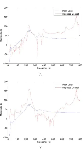
. An H∞ con-troller is to be constructed for the rotor blade example, resulting in a performance at the blades in Fig. 7.
Although the H∞ controller performance can be further improved through, e.g., weighting functions, the problem of tailing performance over any pre-specified frequency band is still difficult to solve. As already commented, the proposed method can be used for such a purpose based on the H∞ controller.
(a)
(b)
Fig. 6.On-line performance of resulting controller (a) Significant Attenuation in z( jω)(b) Disturbance is not enhanced in y( jω).
Case I: In-band Performance Improvement
From Fig. 7, it is seen that the peak around 244 Hz is “dragged down” by the H∞ controller, and thus dis-turbance is attenuated significantly over the first bending mode resonance. However it is also noticed that there is a second bending mode resonance at 225 Hz, where un-fortunately the resulting H∞ controller fails to attenuate the disturbance (H∞ control, by definition, always tries to minimize the frequency response function at the fre-quency with maximum magnitude.) Now the objective is to achieve attenuation over the frequency band covering both the two bending modes resonances. Application of the proposed methodology over, e.g., [200, 300] Hz, gives the result in Fig. 8.
(a)
(b)
Fig. 7.(a) optimal controller performance for blade re-sponse to excitation; (b) magnified view over fre-quency band [240, 280] Hz. Significant vibration suppression is achieved over this frequency band.
controller performance by sacrificing the performance outside, while significantly extending the effective fre-quency band from [240, 280] Hz to [180, 310] Hz. In the case where it is known that there is no disturbance force over the targeted frequency band, e.g., if there is no distur-bance outside [200, 300] Hz in the rotor blade system, then it is desirable to improve the H∞ controller performance over this frequency band without any concern upon the performance outside that frequency band. In fact, as the frequency spectrum of the disturbance entering the system can be estimated in practical engineering (or a band-pass filter can be utilized), it is meaningful to ignore the out-band performance deterioration while concentrating only on the desired frequency band, e.g., covering both the first and the second resonance modes, other than only one of them.
(a)
(b)
Fig. 8.(a) proposed controller performance for blade re-sponse to excitation; (b) magnified view over fre-quency band [180, 310] Hz. Vibration suppression is achieved over this frequency band covering both the first and the second bending modes.
Case II: Out-band Performance Improvement However, if the out-band performance is indeed a con-cern, then the proposed method can be utilized to re-shape the performance over required frequency band. In prac-tice, it might be concerned either low frequency band or high frequency band. An application of the methodology over [100, 200] Hz provides improved performance over the H∞ control over this low frequency band as shown in Fig. 9(a); while an application of the methodology over [300, 500] Hz provides improved performance over the
H∞ control over this high frequency band as shown in
Fig. 9(b). Thus the proposed method can indeed be uti-lized to re-shape control performance over a desired fre-quency band depending on practical interest.
(a)
(b)
Fig. 9.Control performance improvement over (a) low frequency; (b) high frequency.
7. CONCLUSION
Disturbance attenuation either at a discrete frequency or over a frequency band has been considered in this pa-per. A methodology has been proposed for addressing this problem. For many practical engineering systems, it is of-ten feasible to estimate the spectrum of exogenous distur-bance. There are cases where band-pass filters are used intentionally allowing disturbance with specific frequency band entering the system, e.g., radar or sonar detection & anti-detection etc, then the problem of attenuating
distur-bance over (any) prescribed frequency band becomes im-portant. The proposed method thus provides a framework
to systematically tackle the underlying issues such as per-formance limitation, existence of controllers fulfilling pre-scribed performance, as well as the problem of improving the performance of an existing controller etc. Therefore the results presented in this paper provide new insights in
the field of disturbance attenuation in linear systems.
REFERENCES
[1] B. A. Francis, J. W. Helton, and G. Zames, “Optimal con-trollers for linear multivariable systems,” IEEE Transac-tions on Automatic Control, vol. 29, pp. 888-900, 1984. [2] B. A. Francis, A Course in Control Theory,
Springer-Verlag, New York, 1987.
[3] J. Doyle, K. Glover, P. Khargonekar, and B. A. Francis, “State-space solution to standard and control problem,” IEEE Transactions on Automatic Control, vol. 34, no. 8, pp. 831-842, 1989.
[4] K. Glover and J. Doyle, “State space approach to optimal control,” Lecture Notes in Control and Information Sci-ences, Springer-Verlag, pp. 179-218, 1989.
[5] K. Zhou and P. Khargonekar, “An algebraic Riccati equa-tion approach to optimizaequa-tion,” Systems and Control Let-ters, vol. 11, pp. 85-91, 1998. [click]
[6] C. Scherer, P. Gahinet, and M. Chilali, “Multiobjec-tive output-feedback control via LMI optimization,” IEEE Transactions on Automatic Control, vol. 42, no. 7, pp. 896-911, 1997. [click]
[7] G. Arslan and T. Ba¸sar, “Disturbance attenuating controller design for strict-feedback systems with structurally un-known dynamics,” Automatica, vol. 37, pp. 1175-1188, 2001. [click]
[8] Z. P. Jiang, “Nonlinear disturbance attenuation with global stability via output feedback,” Proceedings of the 14th IFAC World Congress, placeCityBeijing, 1999.
[9] C. G. Cassandras, S. Lafortune, and G. J. Olsder, “Intro-duction to the modeling, control and optimization of dis-crete event systems,” Trends in Control, Isidori, A. (editor), Springer-Verlag London, 1995.
[10] Y. Lou and Y. Hong, “Target containment control of multi-agent systems with random switching interconnec-tion topologies,” Automatica, vol. 48, pp. 879-885, 2012. [click]
[11] M. S. Branicky, V. S. Borkar, and S. K. Mitter, “A unified framework for hybrid control: model and optimal control theory,” IEEE Transactions on Automatic control, vol. 43, no. 1, pp. 31-45, 1998. [click]
[12] F. Clarke, “Lyapunov functions and discontinuous stabi-lizing feedback,” Annual Reviews in Control, vol. 35, pp. 13-33, 2011. [click]
[13] G. Battistelli, D. Mari, D. Selvi, A. Tesi, and P. Tesi, “Adaptive disturbance attenuation via logic-based switch-ing,” Systems and Control Letters, vol. 73, pp. 48-57, 2014. [click]
[14] P. Antsaklis and J. Baillieul, (editors), “Special issue on networked control systems,” IEEE Transactions on Auto-matic Control, vol. 49, no. 9, 2004.
[15] J. Zhao, D. J. Hill, and T. Liu, “Stability of dynamical net-works with non-identical nodes: a multiple V-Lyapunov function method,” Automatica, vol. 47, pp. 2615-2625, 2011. [click]
[16] P. P. Menon, C. Edwards, and I. Postlethwaite, “Optimal decentralised static output feedback stabilization of a net-work of dynamical systems,” Systems & Control Letters, vol. 64, pp. 64-71, 2014.
[17] I. D. Landau, M. Alma, A. Constantinescu, J. J. Martinez, and M. Noë, “Adaptive regulation-rejection of unknown multiple narrow band disturbances (a review on algorithms and applications),” Control Engineering Practice, vol. 19, pp. 1168-1181, 2011.
[18] A. Montazeri and J. Poshtan, “Adaptive IIR solution to ac-tive noise and vibration control systems,” IEEE Transac-tions on Automatic Control, vol. 55, no. 11, pp. 2671-2676, 2010.
[19] I. D. Landau, T. B. Airimitoaie, and M. Alma, “IIR Youla-Kucera parameterized adaptive feedforward compensators for active vibration control with mechanical coupling,” IEEE Transactions on Control Systems Technology, vol. 21, no. 3, pp. 765-779, 2013. [click]
[20] S. Q. Zhang, R. Schmidt, P. C. Müller, and X. S. Qin, “Disturbance rejection control for vibration suppression of smart beams and plates under a high frequency excitation,” Journal of Sound and Vibration, vol. 353, no. 29, pp. 19-37, 2015. [click]
[21] H. Kwakernaak, “Mixed sensitivity design,” Proceedings of the 15th Triennial World Congress, placeCityBarcelona, country-regionSpain, 2002.
[22] M. G. Ortega and F. R. Rubio, “Systematic design of weighting matrices for the H∞ mixed sensitivity problem,” Journal of Process Control, vol. 14, pp. 89-98, 2004. [23] S. Li, J. Yang, W. H. Chen, and X. Chen, Disturbance
Observer Based Control: Methods & Applicatioins, CRC Press, 2013.
[24] B. K. Kim and W. K. Chung, “Advanced disturbance ob-server design for mechanical positioning systems,” IEEE Transactions on Industrial Electronics, vol. 50, no. 6, pp. 1207-1216, 2003. [click]
[25] Y. Choi, K. Yang, W. K. Chung, “On the robustness and performance of disturbance observers for second-order systems,” IEEE Transactions on Automatic Control, vol. 48, no.2, pp.315-320, 2003. [click]
[26] Y. Zhang and J. Jiang, “Bibliographical review on recon-figurable fault-tolerant control systems,” Annual Review in Control,vol.32, pp.229-252, 2008. [click]
[27] J. Jiang and X. Yu, “Fault-tolerant control systems: a com-parative study between active and passive approaches,” An-nual Reviews in Control, vol. 36, pp. 60-72, 2012. [click] [28] G. Ferreres and G. Puyou, “Feasibility of H∞ design
spec-ifications: an interpolation method,” International Journal of Control, vol. 78, no. 12, pp. 927-936, 2005. [click] [29] C. Coelho, L. Silveira, and J. Philips, “Passive constrained
rational approximation algorithm using Nevanlinna-Pick interpolation,” Proceedings of the conference on Design, Automation and Test in Europe, pp.923-931, 2002. [30] S. B. Chun and C. W. Lee, “Vibration analysis of
shaft-bladed disk system by using substructure synthesis and as-sumed modes method,” Journal of Sound and Vibration, vol. 189, no. 5, pp. 587-608, 1996.
[31] A. Bas, J. Gilheany, and P. Steimel, “Active vibration con-trol of propeller shafts,” Journal of Sound and Vibration, vol. 136, no. 3, pp. 361-372, 1998.
[32] Y. Chen, V. Wickramasinghe, and D. Zimcik, “Smart spring impedance control algorithm for helicopter blade harmonic vibration suppression,” Journal of Vibration and Control, vol. 11, pp. 543-560, 2005.
[33] P. C. Chen and I. Chopra, “Wind tunnel testing of a smart rotor with individual blade twist control,” Journal of Intel-ligent Material Systems and Structures, vol. 8, pp. 414-425, 1997.
[34] F. K. Straub, H. T. Ngo, V. Anand, and D. B. Domzalski, “Development of a piezoelectric actuator for trailing edge flap control of full scale rotor blades,” Smart Materials and Structures, vol. 10, pp. 25-34, 2001.
Jiqiang Wang received the B.S. degrees
in Industrial Engineering & Management, both from Xi’an Jiaotong University in 2003. He received the Ph.D. degree from the University of Sheffield in 2008. He is currently an Associate Professor at Nan-jing University of Aeronautics & Astro-nautics, after a research fellowship at the University of Strathclyde in 2009. His re-search interests include nonlinear control, vibration control, and aircraft engine control.
Hong Yueis a Senior Lecturer at the
In-dustrial Control Centre at the University of Strathclyde, UK. She received her B.Eng. and M.Eng. degrees in 1990 and 1993, respectively, from Beijing University of Chemical Technology, and her Ph.D. de-gree in 1996 from East China University of Science and Technology. She is inter-ested in multiplanetary research on model-ing, control and optimization of complex systems including pro-cess systems, biomedical networks and renewable energy sys-tems.
Georgi Dimirovski is a Research
(life-time) Professor of Automation & Systems Engineering at SS Cyril & Methodius Uni-versity of Skopje, Republic of Macedonia, and a Guest Professor of Computer and Control Sciences & Information Technolo-gies at Dogus University of Istanbul, Re-public of Turkey. He is an invited pro-fessor of the Graduate Schools of Istanbul Technical University, and of Dokuz Eylul University of Izmir. He is a Foreign Member of the Academy of Engineering Sci-ences of Serbia in Belgrade.
![Fig. 5. Geometry of S and R over [240, 250] Hz: the red slash-dot circles are R-circles; the blue dotted lines are optimal lines for each S-R geometry; while the circles are the optimal choices that are determined by the performance specification.](https://thumb-eu.123doks.com/thumbv2/9libnet/4046028.56995/8.892.469.806.116.727/geometry-circles-geometry-optimal-choices-determined-performance-specification.webp)
![Fig. 7. (a) optimal controller performance for blade re- re-sponse to excitation; (b) magnified view over fre-quency band [240, 280] Hz](https://thumb-eu.123doks.com/thumbv2/9libnet/4046028.56995/9.892.468.807.120.712/optimal-controller-performance-blade-sponse-excitation-magnified-quency.webp)