Rapid Control Prototyping Based on 32-bit ARM
Cortex-M3 Microcontroller for Photovoltaic MPPT
Algorithms
Fuad ALHAJOMAR *, Goksel GOKKUS **, Ahmet Afsin KULAKSIZ ***
*Department of Electrical and Electronics Engineering, Selcuk University, Turkey, 42130 **Department of Electrical and Energy, Nevsehir Haci Bektas Veli University, Turkey, 50300 ***Department of Electrical and Electronics Engineering, Konya Technical University, Turkey, 42250
([email protected], [email protected], [email protected])
‡ Corresponding Author; Ahmet Afsin KULAKSIZ, Turkey, 42250, Tel: +903322233723, Fax: +903322410635, [email protected]
Received: 30.08.2019 Accepted:12.11.2019
Abstract- Since the beginning of the war in Syria, most of the electricity infrastructure has been destroyed, leaving millions
with unreliable energy. In such regions vulnerable to energy insecurity, an alternative means of electricity production is sought. As an attractive option, the interest is directed to solar energy. However, because of a lack of expertise in solar energy conversion and the high cost of smart technology in these regions, people have typically used photovoltaic systems in primitive ways, in which the efficiency of solar energy conversion is low. There is, therefore, a need for inexpensive, easy-to-implement, yet highly efficient and high performing solutions. STMicroelectronics 32-bit ARM as a maximum power point tracking (MPPT) controller offers a potential solution to the problem of low conversion efficiency in stand-alone solar systems. In this study, using Matlab-Simulink and STMicrelectronics-32 bit ARM board, simulation and practical test is set up to evaluate the performance of the Perturbation & Observation, Incremental Conductance, and Fuzzy Logic MPPT algorithms, in order to determine the most appropriate algorithm to use in small scale solar energy systems. Therefore, the objective of this study is to explore rapid control prototyping tools for saving time and effort to the experts in the implementation process of the proposed systems. The results indicate the effectiveness of the fuzzy logic algorithm to draw more energy, decrease oscillation and provide a fast response under variable weather conditions. Furthermore, the three algorithms were able to find and track MPP.
Keywords Photovoltaic, MPPT, Incremental Conductance, Perturbation&Observation, Fuzzy Logic, Rapid Prototyping.
1. Introduction
The continued reliance on fossil fuels for energy production has led to the continued rise in carbon emissions, giving rise to atmospheric changes [1]. Furthermore, it was reported that today 85% of the world’s global energy consumption is met by fossil-based fuels [2], and continual daily increases in global energy use are depleting the supplies of oil and gas, therefore, a tendency to alternative renewable energy sources gained importance [3]. Renewable energy sources are more viable alternatives since they are clean, pollution-free and non-exhaustible. Among all renewable energy systems, the solar energy system has received the most attention due to its ease of implementation and its relatively low cost [4]. Despite advances in PV technology, solar cells have some drawbacks such as the fact
that their energy conversion efficiency is low and their characteristic curve is nonlinear and depends on the irradiance level and ambient temperature (Fig. 1) [5]. To increase the efficiency of the solar cell and optimize the power obtained from the PV system, many maximum power point tracking techniques (MPPT) have been proposed [6-9], such as Perturbation&Observation, Incremental Conductance and Fuzzy Logic. The Maximum Power Point (MPP) is the point on the current-voltage (I-V) curve (Fig. 1) which corresponds to the maximum possible power output for the given PV panel (Pmax), and the Maximum Power Point Tracker (MPPT) is a device that constantly tracks the MPP under variable weather conditions [10]. In this regard, much research has been carried out to evaluate the performance of the three techniques. It has been reported that the Fuzzy Logic controller has better tracking achievement than
conventional techniques and can obtain maximum power in terms of variable temperature and solar insolation conditions [11,12]. In addition, the Fuzzy Logic algorithm increases the conversion efficiency of the PV array [13]. It has been found that the Fuzzy Logic algorithm exhibits the high stability and conversion efficiency needed to maintain maximum power output [14,15]. It has been observed in recent years that there is a great deal of interest in proposing new MPPT techniques based on new artificial intelligence methods [16-18], enhancement the performance of existing conventional MPPT techniques [19] or modified hybrid optimizations [20-22] to increase the efficiency of the energy production of photovoltaic systems. In the light of what has been said above, to date, the proposed hardware solutions suffer from various degrees of complexity, high-cost, inefficiency and power dissipation. Furthermore, in many cases, it is arguably pointless to use a more complicated or more expensive algorithm if a simpler and less expensive one can yield similar results.
In spite of the fact that the proposed system can be used in all remote communities which do not have reliable and sustainable access to electricity, this argument is particularly pertinent to the case of Syria. After the destruction of electric power plants in Syria as a result of the war, and because of the high prices of conventional fuel used to run electrical generators, Syrians have begun using photovoltaic generation systems to meet the daily needs of electric power. Because of the lack of experience in using photovoltaic systems and the high cost of smart technologies, which can improve the produced electricity, Syrians have begun using photovoltaic systems in primitive ways where the efficiency of the generation system is low as shown in Fig. 2. New MPPT techniques are both too complicated and too expensive to offer a feasible solution to improve conversion efficiency in stand-alone (e.g. domestic) solar systems. Instead, there is a need for inexpensive, easy-to-implement, yet highly efficient and high performing solutions. Additionally, these need to be able to be easily integrated with existing systems and be operated under variable weather conditions. The purpose of this paper is to offer an efficient, easy-to-use, high-performance MPPT system to optimize the use of a solar energy system for regions facing insecure production and distribution of electricity.
Very little was found in the literature on the studies investigating the use of STMicroelectronics 32-bit ARM as an MPPT controller, yet it offers an inexpensive, high performance, rapid processing and easy to install solution
Fig. 1. P-V & I-V characteristics of a solar panel.
Fig. 2. The use of solar panels in small scale local
installations in Syria.
that is supported by Matlab. It, therefore, offers a potential solution to the problem of low conversion efficiency in stand-alone solar systems in low resource contexts. In this study, deploying Matlab-Simulink and STMicrelectronics-32 bit development board containing an ARM cortex-M3 microcontroller, the simulation and the practical test is set up for an easy and rapid transition from the simulation to real-time operation on the PV system. The performance of the three aforementioned MPPT algorithms is evaluated to determine the most appropriate algorithm to use in small-scale solar energy systems and the advantages provided by performing rapid control are demonstrated. For the performance evaluation, the mathematical models of the P&O, IC and FL algorithms are designed in Matlab/Simulink. The simulation results are obtained under different irradiation and temperature levels. Furthermore, thanks to the Matlab support of STMicroelectronics, the models designed in Simulink are transferred into the control board and then the practical results are collected. A typical diagram of the MPPT in a PV system is shown in Fig. 3.
In the following section, the principles of each of the three algorithms are outlined in turn. The building of mathematical models in Matlab is then described. Following this, the simulation results are discussed. The practical aspects of the study are then outlined, starting with the transfer of the algorithmic code to the control board, followed by the testing of each algorithmic technique under different weather conditions using a solar simulator. The results of the tests are then discussed, and suggestions are made for the application of the appropriate algorithms in small-scale stand-alone solar energy systems.
2. Maximum Power Point Tracking Algorithms
2.1. Perturbation&Observation (P&O)
This algorithm depends on changing the duty cycle (perturbation) and measuring the output power (observation). The basic principle of the P&O algorithm is summarized in Table 1. First, if the change in duty cycle is positive and change in power is positive, the next perturbation would be positive. On the other hand, if the change in power is negative, the next perturbation would be negative [23].
Table 1. The basic principle of the P&O algorithm
Perturbation Change in power perturbation Next
Positive Positive Positive
Positive Negative Negative
Negative Positive Negative
Negative Negative Positive
2.2. Incremental conductance (IC)
This technique is based on the comparison of the incremental conductance (dI/dV) and the instantaneous conductance (-I/V) [24]. The position of the MPP can be determined by the relationship between dI/dV and -I/V, as given by:
(1)
By using the measured values of Vpv and Ipv at different instants, the MPP can be reached as shown in Fig. 4.
2.3. Fuzzy Logic (FL)
Generally, fuzzy logic control consists of three stages: fuzzification, rule base table lookup, and defuzzification [25,26]. In the fuzzification stage and based on a membership function, shown in Fig. 5, numerical input variables are converted into linguistic variables. Here, five
Fig. 4. The principle of the IC algorithm.
fuzzy levels are used: NB (Negative Big), NS (Negative Small), ZE (Zero), PS (Positive Small), and PB (Positive Big).
In Fig. 5, a&b represent the range of the numerical variable values. Usually, the inputs to a fuzzy logic-based MPPT controller are the error (E) and a change in error (ΔE). It depends on the expert to decide how to compute E and ΔE. The inputs adopted in this study is given by Eqs. (2) and (3).
(2)
and
(3)
Fig.5. The proposed membership function for inputs and
output of the fuzzy logic algorithm.
After calculating E and ΔE, they are converted to the linguistic variables. The fuzzy logic controller output, which in this case is a change in duty cycle ΔD of the power converter, can be found in the proposed rule base as shown in Table 2.
Table 2. The proposed fuzzy logic rule base. ΔE E NB NS ZE PS PB NB ZE ZE NB NB NB NS ZE ZE NS NS NS ZE NS ZE ZE ZE PS PS PS PS PS ZE ZE PB PB PB PB ZE ZE
During the defuzzification stage, the linguistic variables are converted to numerical variables depending on the proposed membership function that is shown in Fig. 5. This generates a signal that will control the power converter of the MPPT.
3. Model of the System
Based on the general mathematical equation of the PV cell, the model of the PV panel was built in Matlab/Simulink. Since the temperature and irradiance have a major effect on the performance of the solar energy systems compared with other factors, only their effects were considered in this study. I-V and P-V characteristics of the PV panel are obtained in three cases. The first case, at variable irradiance levels and constant temperature, is shown in Fig. 6. The second case, at variable temperature levels and constant irradiance, is shown in Fig. 7. The third case, at variable irradiance and variable temperature levels, is shown in Fig. 8.
. MPP of right at the , . MPP of left at the , . MPP at , V I dV dI V I dV dI V I dV dI á -ñ -= ) 1 ( ) ( ) 1 ( ) ( ) ( -= n V n V n P n P n E ) 1 ( ) ( - -= DE E n E n
Fig. 6. I-V and P-V characteristics of the modeled PV panel under variable irradiance levels.
Fig. 7. I-V and P-V characteristics of the modeled PV panel under variable temperature levels.
Fig. 8. I-V and P-V characteristic of the modeled PV panel under variable temperature and variable irradiance levels.
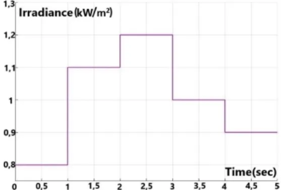
The different levels of solar irradiance and temperature were applied through (5 sec.) as shown in Figs. 9 and 10, respectively.
Fig. 9. The different levels of solar irradiance.
The maximum output powers of the modeled PV panel according to the three mentioned cases are shown in Tables 3, 4 and 5 respectively.
Table 3. The MPP values according to the variable
irradiance levels. Irradiance
level (W/m2) Temperature level (oC) power (W) Maximum
800 25 33
1100 25 46
1200 25 50
1000 25 41
900 25 38
Table 4. The MPP values according to the variable
temperature levels. Irradiance
level (W/m2) Temperature level (oC) power (W) Maximum
1000 25 41
1000 35 38
1000 45 34
A DC-DC boost converter was utilized in the simulation. By controlling the duty cycle of the switching elements, the PV terminal voltage was kept at the point that maximum power is obtained, and also the output voltage of the PV panel was matched with the desired load voltage. The input-output equation of the DC-DC boost converter is:
(4)
Here, Vpv is PV panel output voltage, V0 is DC-DC boost converter output voltage, and D is the duty cycle [27].
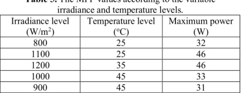
Table 5. The MPP values according to the variable
irradiance and temperature levels. Irradiance level
(W/m2) Temperature level (oC) Maximum power (W)
800 25 32
1100 25 46
1200 35 46
1000 45 33
900 45 31
The proposed system was modeled and simulated using MATLAB/Simulink. Fig. 11 shows our Simulink model. In the simulation study, the three MPPT techniques were simulated and evaluated under three mentioned situations.
4. Simulation Results and Discussion
One significant objective of this research is to investigate an efficient, easy-to-use, high-performance MPPT system to allow the use of electricity in regions without a proper connection to the grid. With a view to evaluate and analyze the maximum power point tracking techniques, an offline simulation was tested in Matlab/Simulink for every algorithm to present a quick transition to final system implementation.
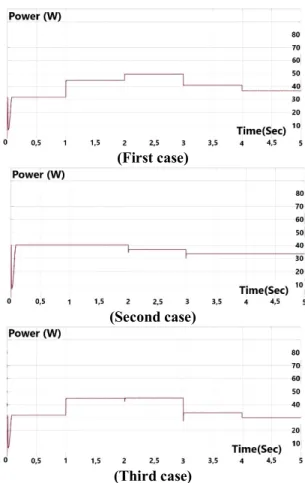
In the three mentioned cases, using each algorithm separately, the withdrawn power from the PV panel was plotted with respect to time (see Figs. 12-14).
Fig. 11. Diagram of the simulated system.
)
1
(
D
Vo
(First case)
(Second case)
(Third case)
Fig. 12. Output power of solar panel with P&O algorithm.
(First case)
(Second case)
(Third case)
Fig. 13. Output power of solar panel with IC algorithm.
(First case)
(Second case)
(Third case)
Fig. 14. Output power of solar panel with FL algorithm.
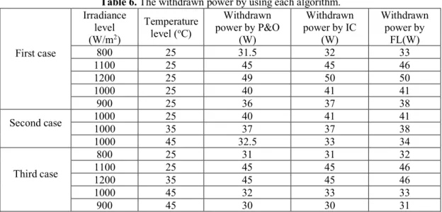
From the collected simulation results, it can be seen that all the tested algorithms were able to detect and track the maximum power point despite the instantaneous change in the irradiance and temperature. It is also clear that both P&O and IC algorithms were able to make the operating point of the system near the MPP, while FL algorithm made the operating point exactly at the MPP. Thus, the withdrawn energy from the solar panel using the FL algorithm in the three cases is greater than the energy produced using the other algorithms, as shown in Table 6.
As shown in Fig. 12 and Fig. 13, the P&O and IC algorithms showed efficient dynamic performance, but steady-state oscillations were larger at the MPP, which made the MPPT accuracy low. The simulation results indicate that the steady-state oscillation at the maximum power point was less when using the FL algorithm, Fig. 14, resulting in lower energy loss and increased system efficiency.
5. Experimental Validation and Discussion
Extensive experimental studies have been carried out to evaluate the MPPT algorithms. Significant results have been obtained by taking advantage of advancements in embedded systems technology and discussed in this section. The goal was to compare the described MPPT algorithms under strictly the same conditions. The hardware arrangement of the system is shown in Fig. 15.
Table 6. The withdrawn power by using each algorithm. First case Irradiance level (W/m2) Temperature level (oC) Withdrawn power by P&O (W) Withdrawn power by IC (W) Withdrawn power by FL(W) 800 25 31.5 32 33 1100 25 45 45 46 1200 25 49 50 50 1000 25 40 41 41 900 25 36 37 38 Second case 1000 1000 25 35 40 37 41 37 41 38 1000 45 32.5 33 34 Third case 800 25 31 31 32 1100 25 45 45 46 1200 35 45 45 46 1000 45 32 33 33 900 45 30 30 31
The system was designed to work at 500 W and STMicroelectronics-32 bit ARM, which has not been used before in such an application was adopted as a controller in this study. In addition, the DC-DC boost converter was used to raise the input voltage to the required value and a solar panel simulator was used to generate the characteristic of real PV panels. After the simulation of the control algorithm (model in-the-loop-simulation) for MPPT, STMicroelectronics 32-bit ARM board is used to test and optimize the system hardware in real-time (hardware-in-the-loop simulation).
The test was set up in three stages as shown in Fig. 16. The first stage at constant temperature (25oC) and constant irradiance level (1000 W/m2), the second stage at constant temperature (25oC) and variable irradiance level from (100 W/m2) to (1000 W/m2) then to (100W/m2), the third stage at constant irradiance (1000W/m2) and variable temperature from (0oC) to (75oC) then to (0oC). The duration of each stage is 500 seconds. Through the three stages, the three algorithms were employed and practical results were collected.
Figs. 17, 18 and 19 show the current, voltage and power respectively produced from the solar PV system by using P&O algorithm in the three aforementioned stages. The results show that P&O algorithm was able to find and track the maximum power point. However, there was a steady-state oscillation at the MPP, which led to some loss in produced power.
Using the IC algorithm, the current, voltage and power produced from the solar PV system are shown in Figs. 20, 21 and 22, respectively. The results show that the IC algorithm was able to detect and track the maximum power point with a smaller steady-state error at MPP than P&O algorithm, and that improved the efficiency of the MPPT controller.
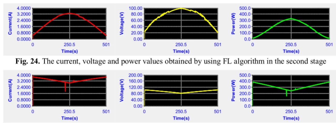
The fuzzy-based MPPT routine was also employed. As demonstrated from the practical results, the FL algorithm improved the tracking performance of the controller concerning to steady-state and dynamic characteristics. It was also able to make the operating point exactly at MPP. Figs. 23, 24 and 25 show the current, voltage and power produced from the solar system by using FL algorithm.
Fig. 16. The three stages used to test the algorithms
Fig. 17. The current, voltage and power values obtained by using P&O algorithm in the first stage
Fig. 18. The current, voltage and power values obtained by using P&O algorithm in the second stage
Fig. 19. The current, voltage and power values obtained by using P&O algorithm in the third stage
Fig. 20. The current, voltage and power values obtained by using IC algorithm in the first stage
Fig. 21. The current, voltage and power values obtained by using IC algorithm in the second stage
Fig. 22. The current, voltage and power values obtained by using IC algorithm in the third stage
Fig. 23. The current, voltage and power values obtained by using FL algorithm in the first stage
0.0 202.0 404.0 606.0 808.0 1,010.0 Ir ra d ia n c e (W /㎡ ) 0.0 8.0 16.0 24.0 32.0 40.0 T e m p e ra tu re (℃ ) 0 100 200 300 400 500 Time(s) Irradiance Temperature CTG 0.0 202.0 404.0 606.0 808.0 1,010.0 Ir ra d ia n c e (W /㎡ ) 0.0 8.0 16.0 24.0 32.0 40.0 T e m p e ra tu re (℃ ) 0 100 200 300 400 500 Time(s) Irradiance Temperature slow_ram_v3 0.0 202.0 404.0 606.0 808.0 1,010.0 Ir ra d ia n c e (W /㎡ ) 0.0 18.0 36.0 54.0 72.0 90.0 T e m p e ra tu re (℃ ) 0 100 200 300 400 500 Time(s) Irradiance Temperature CGVT_V1 0.0000 0.8000 1.6000 2.4000 3.2000 4.0000 C u rr en t( A ) 0 251 502 Time(s) 0.00 20.00 40.00 60.00 80.00 100.00 V o lt ag e( V ) 0 251 502 Time(s) 0.0 100.0 200.0 300.0 400.0 500.0 P o w er (W ) 0 251 502 Time(s) 0.0000 0.8000 1.6000 2.4000 3.2000 4.0000 C u rr en t( A ) 0 250.5 501 Time(s) 0.00 20.00 40.00 60.00 80.00 100.00 V o lt ag e( V ) 0 250.5 501 Time(s) 0.0 100.0 200.0 300.0 400.0 500.0 P o w er (W ) 0 250.5 501 Time(s) 0.0000 1.0000 2.0000 3.0000 4.0000 5.0000 C u rr en t( A ) 0 251 502 Time(s) 0.00 40.00 80.00 120.00 160.00 200.00 V o lt ag e( V ) 0 251 502 Time(s) 0.0 100.0 200.0 300.0 400.0 500.0 P o w er (W ) 0 251 502 Time(s) 0.0000 1.0000 2.0000 3.0000 4.0000 5.0000 C u rr en t( A ) 0 250.5 501 Time(s) 0.00 20.00 40.00 60.00 80.00 100.00 V o lt ag e( V ) 0 250.5 501 Time(s) 0.0 100.0 200.0 300.0 400.0 500.0 P o w er (W ) 0 250.5 501 Time(s) 0.0000 0.8000 1.6000 2.4000 3.2000 4.0000 C u rr en t( A ) 0 250.5 501 Time(s) 0.00 40.00 80.00 120.00 160.00 200.00 V o lt ag e( V ) 0 250.5 501 Time(s) 0.0 100.0 200.0 300.0 400.0 500.0 P o w er (W ) 0 250.5 501 Time(s) 0.0000 1.0000 2.0000 3.0000 4.0000 5.0000 C u rr en t( A ) 0 250.5 501 Time(s) 0.00 20.00 40.00 60.00 80.00 100.00 V o lt ag e( V ) 0 250.5 501 Time(s) 0.0 100.0 200.0 300.0 400.0 500.0 P o w er (W ) 0 250.5 501 Time(s) 0.0000 0.8000 1.6000 2.4000 3.2000 4.0000 C u rr en t( A ) 0 250.5 501 Time(s) 0.00 20.00 40.00 60.00 80.00 100.00 V o lt ag e( V ) 0 250.5 501 Time(s) 0.0 100.0 200.0 300.0 400.0 500.0 P o w er (W ) 0 250.5 501 Time(s)
Fig. 24. The current, voltage and power values obtained by using FL algorithm in the second stage
Fig. 25. The current, voltage and power values obtained by using FL algorithm in the third stage
Finally, although all the tested algorithms were able to find and track the MPP under variable weather conditions, the results showed that the Fuzzy Logic technique exhibited better performance in terms of efficiency than the conventional techniques, (P&O and IC). In this regard, the oscillations present in the Fuzzy Logic algorithm was also less than the other algorithms. Moreover, the response was better. This corresponds to the simulation results obtained. In other words, the collected practical results and simulation results validate each other.
These findings suggest that the Fuzzy Logic algorithm applied to STMicroelectronics board can produce low cost yet effective MPPT systems to ensure electricity production from stand-alone solar energy systems in areas facing power outage problems.
6. Conclusion
This study responded to a need to produce an inexpensive, easy-to-implement, yet highly efficient and high performing MPPT system for the regions needing new means of electricity production to optimize the use of small-scale solar energy system solutions under variable weather conditions. Using the STMicroelectronics 32-bit ARM, the designed MPPT controller offers a potential solution since it is cheap and has high-performance and high processing speed. Additionally, as it is supported by Matlab, there is no need to write any control code. The simulation and practical tests were set up to verify the performance of the P&O, IC and FL MPPT algorithms in order to determine the most appropriate algorithm. In addition to the comparison of the results, by means of the rapid prototyping, the design process could be quicker and fast adjustments on each algorithm to obtain satisfactory results could be made. The simplification of the code generation process could direct the focus on design and testing by decreasing time-consuming programming process. Consequently, the simulation and real-time implementation results were obtained in harmony and the results indicated an accurate and reliable solution.
The findings revealed that the Fuzzy logic algorithm is preferable to conventional techniques. It had better tracking achievement and was able to obtain maximum power in terms of variable irradiance and variable temperature. In addition, the Fuzzy Logic algorithm also reduced the steady-state oscillations at the MPP resulting in decreased power
losses. Future efforts will be directed towards implementing one of the new optimization algorithms dealing with partial shading conditions by using STMicroelectronics-32 bit ARM.
Acknowledgements
This paper is granted by Selcuk University scientific research projects coordinate (BAP) under Project No 17401144. Fuad ALHAJOMAR would like to express his gratitude to The Council for At-Risk Academics (Cara), United Kingdom.
References
[1] U. Agbulut, I. Ceylan, A.E. Gurel and A. Ergun, “The history of greenhouse gas emissions and relation with the nuclear energy policy for Turkey”, International Journal of Ambient Energy Volume 40, Issue 8, Published online: 07 Jan 2019.
[2] U. Agbulut, “Turkey’s electricity generation problem and nuclear energy policy”, Energy Sources, Part A: Recovery, Utilization, and Environmental Effects, Volume 41, Issue 22, Published online: 30 Mar 2019. [3] U. Agbulut, S. Saridemir, S. Albayrak, “Experimental
investigation of combustion, performance and emission characteristics of a diesel engine fuelled with diesel– biodiesel–alcohol blends”, Journal of the Brazilian Society of Mechanical Sciences and Engineering, 41: 389, 2019.
[4] M. Bahrami, R. G. Ghoachani, M. Zandi, M. Phattanasak, G. Maranzanaa, B. N. Mobarakeh, S. Pierfederici, and F. M. Tabar, “Hybrid maximum power point tracking algorithm with improved dynamic performance”, Renewable Energy 130 (2019) 982-991, 2019.
[5] S. Mule, R. Hardas, and N. R. Kulkarni, “P&O, IncCon and Fuzzy Logic Implemented MPPT Scheme for PV Systems using PIC18F452”, IEEE WiSPNET Conference, 2016.
[6] K. Sundareswaran, V. V. Kumar, and S. Palani, “Application of a combined particle swarm optimization and perturb and observe method for MPPT
0.0000 0.8000 1.6000 2.4000 3.2000 4.0000 C u rr en t( A ) 0 250.5 501 Time(s) 0.00 20.00 40.00 60.00 80.00 100.00 V o lt ag e( V ) 0 250.5 501 Time(s) 0.0 100.0 200.0 300.0 400.0 500.0 P o w er (W ) 0 250.5 501 Time(s) 0.0000 0.8000 1.6000 2.4000 3.2000 4.0000 C u rr en t( A ) 0 250.5 501 Time(s) 0.00 40.00 80.00 120.00 160.00 200.00 V o lt ag e( V ) 0 250.5 501 Time(s) 0.0 100.0 200.0 300.0 400.0 500.0 P o w er (W ) 0 250.5 501 Time(s)
in PV systems under partial shading conditions”, Renewable Energy, 75 (2015) 308-317, 2015.
[7] X. Li, H. Wen, Y. Hu, and L. Jiang,, “A novel beta parameter based fuzzy-logic controller for photovoltaic MPPT application”, Renewable Energy, Vol. 130, pp. 416-427, 2019.
[8] K. Kajiwara, N. Matsui, and F. Kurokawa, "A new MPPT control for solar panel under bus voltage fluctuation," 2017 IEEE 6th International Conference on Renewable Energy Research and Applications (ICRERA), pp. 1047-1050, San Diego, CA, 2017. [9] B. Veerasamy, A. R. Thelkar, G. Ramu and T.
Takeshita, "Efficient MPPT control for fast irradiation changes and partial shading conditions on PV systems," 2016 IEEE International Conference on Renewable Energy Research and Applications (ICRERA), pp. 358-363, Birmingham, 2016,.
[10] O. Kaplan and F. Issi, "An android based application and simulation of multiple photovoltaic panels," 2017 IEEE 6th International Conference on Renewable Energy Research and Applications (ICRERA), pp. 925-930, San Diego, CA, 2017.
[11] Y. Yi Hong, A. A. Beltran, and A.C. Paglinawan, “Real-Time Simulation of Maximum Power Point Tracking Control U sing Fuzzy Logic for Stand Alone PV System”, IEEE Transactions on Industrial Electronics, 2017.
[12] F. Alhaj Omar, G. Gokkus, A. A. Kulaksiz, “Şebekeden Bağımsız FV Sistemde Maksimum Güç Noktası Takip Algoritmalarının Değişken Hava Şartları Altında Karşılaştırmalı Analizi”, Konya Journal of Engineering Sciences, Vol. 7, No. 3, pp. 585-594, 2019.
[13] R. Mahalakshmi, A. Kumar, and A. Kumar, “Design of Fuzzy Logic Based Maximum Power Point Tracking Controller for Solar Array for Cloudy Weather Conditions”, IEEE Towards Sustainable Energy, 2014. [14] M. Dhimish, V. Holmes, B. Mehrdadi, and M. Dales,
“Comparing Mamdani Sugeno fuzzy logic and RBF ANN network for PV fault detection”, Renewable Energy 117 (2018) 257-274, 2018.
[15] Ch. Chuang , P. Chen, Ch. Hsu, J. Yu Li, and J. Fuh Chen, “Novel maximum power point tracker for PV systems using interval type-2 fuzzy logic controller”, IEEE Transactions on Industrial Electronics, 2017. [16] A. Chouksey, S. Awasthi, and S.K. Singh, “Fuzzy
cognitive network-based maximum power point tracking using a self-tuned adaptive gain scheduled fuzzy proportional integral derivative controller and improved artificial neural network-based particle swarm optimization. Fuzzy Sets and Systems”, Available online 22 February 2019.
[17] A. Harragab, and S. Messaltic, “IC-based Variable Step Size Neuro-Fuzzy MPPT Improving PV System
Performances,” Energy Procedia, Volume 157, Pages 362-374, January 2019.
[18] K. Amara et al., "Improved Performance of a PV Solar Panel with Adaptive Neuro Fuzzy Inference System ANFIS based MPPT," 2018 7th International Conference on Renewable Energy Research and Applications (ICRERA), pp. 1098-1101, Paris, 2018. [19] C. Bertin Nzoundja Fapi, P. Wira, M. Kamta, A. Badji
and H. Tchakounte, “Real-Time Experimental Assessment of Hill Climbing MPPT Algorithm Enhanced by Estimating a Duty Cycle for PV System”, International Journal Of Renewable Energy Research, Vol. 9, No.3, September, 2019.
[20] H. Li, D. Yang, W. Su, J. Lü, and X.Yu, “An Overall Distribution Particle Swarm Optimization MPPT Algorithm for Photovoltaic System Under Partial Shading,” IEEE Transactions on Industrial Electronics, Volume: 66, Issue: 1, Jan. 2019.
[21] S. Padmanaban, N. Priyadarshi, J. H. Nielsen, and M. S. Bhaskar, “A Novel Modified Sine-Cosine Optimized MPPT Algorithm for Grid Integrated PV System under Real Operating Conditions,” IEEE, Volume: 7, 01 January 2019.
[22] N. Priyadarshi, A. K. Sharma and F. Azam, “A Hybrid Firefly Asymmetrical Fuzzy Logic Controller ba sed MPPT for PV Wind Fuel Grid Integration”, International Journal Of Renewable Energy Research, Vol.7, No.4, 2017.
[23] K. Nabil, M. Nazih, and O.Rachid, “General review and classification of different MPPT Techniques,” Renewable and Sustainable Energy Reviews, pp. 1–18, 2017.
[24] A. Safari, and S. Mekhilef, “Simulation and Hardware Implementation of Incremental Conductance MPPT with Direct Control Method Using Cuk Converter,” IEEE Transactions on Industrial Electronics, Vol. 58, No. 4, April 2011.
[25] M. Kumar, S.R. Kapoor , R. Nagar, and A. Verma, “Comparison between IC and Fuzzy Logic MPPT Algorithm Based Solar PV System using Boost Converter,” International Journal of Advanced Research in Electrical, Electronics and Instrumentation Engineering, Vol. 4, Issue 6, June 2015.
[26] M. K. Al-Nussairi, R. Bayindir, and E. Hossain, "Fuzzy logic controller for Dc-Dc buck converter with constant power load," 2017 IEEE 6th International Conference on Renewable Energy Research and Applications (ICRERA), pp. 1175-1179, San Diego, CA, 2017. [27] S. Soltani, and M. J. Kouhanjani, “Fuzzy Logic Type-2
Controller Design for MPPT in Photovoltaic System,” 22nd Electrical Power Distribution Conference, April 2017.