TURKISH-GERMAN UNIVERSITY
INSTITUTE FOR GRADUATE STUDIES IN SCIENCE AND ENGINEERING MASTER OF SCIENCE IN MANUFACTURING TECHNOLOGY
Master Thesis
Development of metal-composite hybrid joint for
truck fender components
by
Mertcan Hacioglu
Registration Number: 1661011103
Supervisors:
Prof. Dr.-Ing. Markus Stommel
Dr. Mehmet Ipekoglu
M. Sc. Fabian Günther
Submitted on 06.05.2019
Table of Contents
1 Introduction... 1
Purpose and Approach ... 2
2 State-of-the-Art ... 4
Composite Materials ... 4
2.1.1 Types of Composite Materials ... 4
Short fiber reinforced composite ... 10
Production Methods of Composites... 14
2.3.1 Injection Molding ... 15
Design Considerations for Injection Molded Parts ... 17
Hybrid Joint ... 19
Material Modelling of Short Fiber Reinforced Composite ... 24
3 Design and Finite Element Analysis ... 29
The Real Case Scenario – Truck Fender Components ... 29
Initial Concept Study ... 31
Design and Finite Element Analysis: Connection Holes ... 32
Design and Finite Element Analysis: Development of Hybrid Joint ... 36
Design and Finite Element Analysis: Reinforcement of Hybrid Joint ... 40
Design Improvements ... 43
4 Verification of the Final Design ... 47
5 Conclusion and Outlook ... 51
Abstract
The lightweight design is a general concern in many industries. The aim is reducing the weight without any loss of strength and durability. Fiber reinforced composite materials come forward due to their high stiffness to weight ratio in order to satisfy this aim. The necessity of using a composite material with a metal component can be arisen in certain applications and an applicable connection is required between them. Using fasteners or adhesive is commonly used method; however, it requires additional assembly process and the fasteners bring extra weight. An intrinsic hybrid joint, which is making an assembly of two different components in a production stage, is more effective in terms of process steps and cycle time. Development of a hybrid joint between two hollow components and product development are the main concerns of this thesis. The application example was chosen as a truck fender holder and a console of a truck from Mercedes-Benz.
Combination of grooving or alternatively turning and injection molding was chosen as production and joining processes. Two groove types, which are ball end groove and U groove, were investigated in terms of mechanical interlocking and tensile test analyses were performed to see the effect of type and width of the groove on the mechanical interlocking. Additionally, bending analyses were conducted to design the required support for the hybrid joint from outside. Lastly, compression analyses were performed to simulate the torque applied to the fasteners to mount the console to the chassis. After finalizing the design with feedbacks from these analyses, four different analyses defined by Mercedes-Benz Turk were conducted to verify the usability of the developed product and the joint method. The result of the analyses showed that developed hybrid joint and new design are able to carry the defined load and the component, which is currently in use, can be replaced with the new design.
List of Figures
Figure 1.1 Truck fender components ... 1
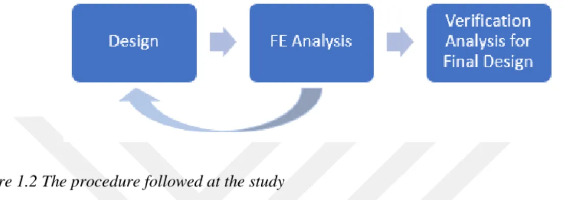
Figure 1.2 The procedure followed at the study ... 2
Figure 2.1: Schematic view of amorphous and semi-crystalline morphology ... 6
Figure 2.2: Categorized thermoplastic resins ... 7
Figure 2.3: Categorized thermoplastic resins regarding the cost ... 7
Figure 2.4: Types of composite reinforcement ... 8
Figure 2.5: Types of continuous and discontinuous fibers... 9
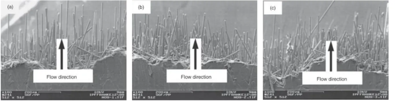
Figure 2.6 Fiber orientation variation from the left side of the composite to the right side (a) left side, (b) middle, (c) right side ... 13
Figure 2.7 Fiber motion in resin flow ... 13
Figure 2.8 Major production methods of composites ... 14
Figure 2.9 Components of the injection molding machine ... 15
Figure 2.10 A typical plasticizing screw with zones ... 16
Figure 2.11 Schematic representation of the injection unit and mold cavities ... 16
Figure 2.12 Hybrid component production technology ... 19
Figure 2.13 Effect of roughness and fiber content on mechanical interlocking ... 20
Figure 2.14: Process chain of intrinsic hybridization by deep drawing ... 21
Figure 2.15 Process chain of intrinsic hybridization during resin transfer molding ... 21
Figure 2.16 Process chain of intrinsic hybridization during integral tube blowing ... 22
Figure 2.17 Process combination of hydroforming and injection molding... 23
Figure 2.18 Intrinsic hybrid joint and result of pull-out simulation ... 23
Figure 2.19 Data exchange procedure ... 24
Figure 2.20 (a) Moldflow setup, (b) Fiber orientation plot ... 25
Figure 2.21 Comparison of the material models ... 26
Figure 2.22 Comparison of tetrahedral elements in terms of element size and element type .. 28
Figure 3.1 Truck fender and its components ... 29
Figure 3.2 Dimensions of the console and the tube ... 30
Figure 3.3 Initial concept design ... 31
Figure 3.4 Simulation of compressive load ... 32
Figure 3.6 Effect of a metal insert on compressive displacement (10 times magnified) ... 34
Figure 3.7 New designs (a) circumferential support with gussets, (b) wall support with gussets and ribs, (c) wall support with additional net structure ... 35
Figure 3.8 Groove types: (a) ball end groove, (b) U groove ... 36
Figure 3.9 Tensile test to compare the mechanical interlocking ability of different groove types ... 37
Figure 3.10 Stress and displacement values of groove types (10 times magnified) ... 38
Figure 3.11 Types of ball end groove ... 39
Figure 3.12 Effect of groove width on tensile displacement ... 40
Figure 3.13 Available space for reinforcement on the console ... 41
Figure 3.14 Design groups: (a) First design group, (b) Second design group ... 41
Figure 3.15 Stress values after bending analysis... 42
Figure 3.16 Effect of additional rib ... 43
Figure 3.17 Required design changes due to depth/width ratio ... 44
Figure 3.18 Final design ... 44
Figure 3.19 Stress value of the final design ... 45
Figure 3.20 New console design on the chassis ... 46
Figure 3.21 Fiber orientation from Moldflow analysis ... 46
Figure 4.1 Material properties ... 47
Figure 4.2 Finite Element Model for modal analysis ... 48
Figure 4.3 Result of modal analysis ... 48
Figure 4.4 Result of dynamic load analysis ... 49
List of Tables
Table 2.1: The differences between thermosets and thermoplastics ... 5
Table 2.2: Properties of amorphous and semi-crystalline morphology ... 6
Table 2.3: Properties of composite reinforcing fibers ... 10
Table 2.4 Properties of commonly used matrices in SFRP ... 12
Table 2.5 Tensile strength of POM and short glass fiber reinforced POM ... 17
Table 2.6 Recommended wall thickness for plastics ... 18
Table 2.7 Comparison of computation time ... 26
List of Abbreviations
ABS Acrylonitrile butadiene styrene
CAD Computer Aided Design
CAE Computer Aided Engineering
CF Carbon fiber
CFRP Continuous Fiber Reinforced Polymer
FE Finite Element
FEA Finite Element Analysis
FEM Finite Element Method
GF Glass Fiber
PA6 Polyamide 6
PBT Polybutylene terephthalate
PEEK Polyether ether ketone
POM Polyoxymethylene
PP Polypropylene
RTM Resin Transfer Molding
1
Introduction
Lightweight design has been one of the main concerns in the automotive industry since the last decades. It is aimed to reduce the fuel consumption as well as CO2 emission. Additionally, with
the usage of electricity in the automobiles, buses and trucks as a power source, weight reduction gained more importance. Since the battery capacity is limited, total weight of the system has a significant effect on the travel range. Therefore, any weight reduction in any component is important for the companies. Weight reduction can be achieved either with lighter material or design optimization (Koch et al. (2016) and Wang et al. (2016)).
This thesis focuses on the development of a method to connect composite and steel hollow components and it is conducted incorporation with Mercedes-Benz Turk. An example application was chosen as a truck fender holder, which consists of a steel tube and a steel console, is used at Mercedes-Benz truck as shown in Figure 1.1. The tube, which carries the fender, is friction-welded to the console and the console is assembled to the chassis with three bolts. In this assembly, the console is the critical part since it is exposed to high loads due to the weight of the tube and the fender as well as dynamic loads due to rough road condition. Therefore, the material of the console is aimed to change to a composite to make the study case more challenging and make more contribution to future studies. Additionally, a hybrid joint is developed to mount the composite console with the steel tube. Material change brings additional task which is redesign of the console as a composite with some restrictions which are no change on the connection hole position, the pipe and the gap below the console.
Purpose and Approach
This study has two main purposes which are the development of a connection between metal and composite components and designing a part to replace the steel console. FEA is used for improving the design and connection method as well as verifying the final assembly. The procedure followed at this thesis can be seen in Figure 1.2.
Figure 1.2 The procedure followed at the study
Firstly, literature survey was performed to collect information about composite materials, production methods, metal-composite hybrid joint methods and material modeling. Since the geometry of the console is complex, it is suitable for injection molding. Due to the loading conditions, reinforcement is required to strengthen the component. Therefore, injection molding with short fiber reinforced polymer is the initial idea as a production method. There is a variety of SFRP to be used; however, the material should be cost-effective and ensure the durability requirements. Considering these parameters, PP, PA6 and PBT, which are easily accessible in the industry, are compared. Due to its common usage in the industry and its properties, especially toughness value to absorb dynamic loads on rough road condition, glass fiber reinforced PA6 is preferred as a material. Albert et al. (2015) conducted a study to connect metal and composite components with hydroforming and injection molding. Instead of a wavy metal surface, exactly defined grooves on a metal tube were investigated in terms of mechanical interlocking. The suggested production method is a combination of grooving and injection molding. Grooves are opened on the metal tube and then the composite component is overmolded on the tube. With this method, no additional assembly process is required. Components are connected during the production of the composite part which is called as intrinsic joint.
Secondly, the design process is divided into three subcategories which are strengthening the connection holes, development of a hybrid joint and strengthening this joint. Since the console
is mounted to the chassis with bolts and nuts, there is high compression load on the connection holes due to the applied tightening torque. Effect of a metal insert is investigated to resist against this torque. Compression analysis is performed to compare the different reinforced geometries. In another subcategory, two types of grooves with variational width values, which are ball end groove and U groove, are investigated. Analyses of tensile test are performed to make a comparison in terms of mechanical interlocking and find the best groove type with an optimum width value. In the last subcategory, different number of ribs and gussets are used to support the hybrid joint. Bending analysis is conducted to see the effect of the support on displacement and stress distribution. After each FEA, the design is improved and the same procedure is followed until the acceptable stress and displacement values are reached.
Finally, verification analyses with four steps, which are defined by Mercedes-Benz Turk CAE Team are conducted on the final design by Mercedes-Benz Turk CAE Team and Assan Hanil in order to see the performance of the new design and joint method and its capability to replace the current component.
2
State-of-the-Art
The aim of this chapter is to create fundamental knowledge related to the performed work. Firstly, types of composites are explained briefly and the importance of material selection is mentioned. Then SFRP is discussed in details and challenges related to manufacturing and material simulation are addressed. In addition, design consideration for injection molding is explained. It is followed by studies conducted in the subject of a hybrid joint. Lastly, the main points of FEA are given to clarify the background of the analyses performed.
Composite Materials
Composite material is defined as a combination of two or more materials in order to have a new material with superior properties than each used material. Each material keeps its original properties such as chemical, physical and mechanical. Components of composite material are reinforcement and matrix. The prominent advantage of these materials is high strength and stiffness with low density. This is the reason why composite materials are more favored for weight reduction applications than bulk materials (Campbell, 2010).
2.1.1 Types of Composite Materials
Composite materials are classified according to used matrix and reinforcement. The strength and stiffness of the material are provided by the reinforcement which is usually a fiber. The matrix keeps the fiber in the desired orientation as well as protecting them from abrasive and environmental effects by surrounding them (Campbell, 2010). Types of matrix and fibers are explained in details below.
The matrix is the continuous phase of the composite material and it can be either polymer, metal or ceramic. While polymers have low strength and stiffness, metals offer high ductility with average strength and stiffness. Ceramics have higher strength and stiffness when compared with the other types but they are brittle. A strong bond is formed between the matrix and the fiber in polymer and metal matrix composites. Ceramic matrix is mostly used to increase toughness. Since metal and ceramic matrices are processed at high temperature, they are more expensive than the polymer matrices. Thermosets and thermoplastics are two types of polymer matrices. A thermoset resin has low viscosity and cures during the process; whereas, a thermoplastics has high viscosity and it is heated above melting temperature to be processed (Campbell, 2010). A comparison of the two types of polymer matrices is given in Table 2.1.
Table 2.1: The differences between thermosets and thermoplastics (Kaw, 2006)
Thermoplastics Thermoset
Soften on heating and pressure, and thus easy to repair High strains to failure
Indefinite shelf life Can be reprocessed
Not tacky and easy to handle Short cure cycles
Higher fabrication temperature and viscosities have made it difficult to process
Excellent solvent resistance
Decompose on heating Low strains to failure Definite shelf life Cannot be reprocessed Tacky
Long cure cycles
Lower fabrication temperature Fair solvent resistance
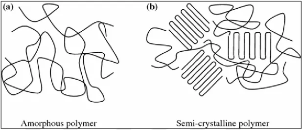
In thermosetting resin, chemical cross-linking converts liquid resin into a hard rigid solid and this results in a tightly bounded three-dimensional structure. Molecular units in this structure, length and density of the cross-links affect the mechanical properties. Common examples of thermosetting resin are epoxy, vinyl ester and unsaturated polyester. In contrast to thermosetting resins, thermoplastics do not have a cross-linked structure. Origin of their strength and stiffness is the monomer units and the very high molecular weight. Thermoplastics are categorized according to their morphology which means the orientation of the molecules of the polymer in the solid state. These categories are amorphous and semi-crystalline. While amorphous morphology has a high aggregation of molecular entanglements which can be considered as cross-links, semi-crystalline morphology has a high degree of molecular order. During heating, amorphous morphology disentangles and changes its form from a rigid solid to a viscous liquid. However, heating crystalline morphology causes melting of the crystalline phase and this ends up with an amorphous viscous liquid. Both types of thermoplastics can have anisotropic properties according to the solidification conditions. The molecular orientation which arises during melt flow in the injection is the reason of anisotropic properties for amorphous resins. Likely, a semi-crystalline morphology can develop its orientation regarding the temperature gradients in the melt which causes preferential growth in some directions (Hull et al., 1996).
When this study is considered, thermoplastics comes forward due to more suitable properties such as high strains to failure and short cure cycle. There are more than 60 thermoplastics
available to produce a composite. Schematic view and main properties of both morphology type of thermoplastics can be seen in Figure 2.1 and Table 2.2 respectively.
Figure 2.1: Schematic view of amorphous and semi-crystalline morphology (Piergiovanni, 2016) Table 2.2: Properties of amorphous and semi-crystalline morphology (Maki)
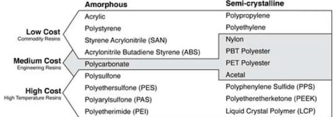
Figure 2.2: Categorized thermoplastic resins (polymers.com.au)
Apart from properties, cost is another important criterion for choosing the resin in the industrial application. According to Maki, the toughest physical requirements can be met with a composite but it should be cost-effective to meet the customers' cost expectation. He categorized the resins into three classes: low cost/commodity resins with a cost less than $3.00/kg, medium cost/engineering resins with a cost between $3.00-$6.00/kg and high cost/high-temperature resins with a cost above $6.00/kg. There is a direct relationship between the temperature resistance of the resin and cost. In that way, it is important to specify the thermal requirements of the application correctly. Resins group according to cost is given in Figure 2.3.
The second component of the composite material is the reinforcing phase. This phase gives the strength and stiffness to a composite and it is mostly harder and stronger than the resin. The reinforcement is categorized as particulate, flake and fiber reinforcement as seen in Figure 2.4. The dimension of particulate reinforcement is approximately equal in all direction. Their shape can be spherical, platelets or any other geometry. Particulate composites have lower strength value than the continuous fiber composites but they are usually cheaper (Campbell, 2010). There are flat reinforcements of matrices in flake composites. Some examples of flake reinforcement are glass, aluminum and silver. This type of composite has high flexural modulus against bending and higher strength; however, it is hard to orient the flakes (Kaw, 2006). The third type of reinforcement is fiber which has a length many times more than its diameter. The aspect ratio, which is the ratio of the length to diameter (l/d), is used to define the dimensions of fiber. While continuous fibers have a high aspect ratio, discontinuous fibers have a low aspect ratio. It is possible and easier to give desired orientation to continuous fiber composites, nevertheless, discontinuous fibers have mostly random orientation due to the difficulty of placement. Unidirectional, woven cloth and helical winding can be given as examples for continuous fibers. Chopped and mat fibers are the example of discontinuous fibers as seen in Figure 2.5 (Campbell, 2010).
Figure 2.5: Types of continuous and discontinuous fibers (Campbell, 2010)
Because of the better strength and stiffness properties, fiber reinforcement is most favored in the automotive industry. Glass, carbon, boron and aramid fibers are commonly used fiber types. Properties of these fiber types are compared in Table 2.3.
Glass fibers were the first fibers which were used to produce the composite material. They have good chemical stability and heat resistance, high tensile strength and low tensile strain. Glass fibers are cheaper when compared with other types of fibers. There are different types of glass fiber such as A-glass, E-glass and S-glass. E-glass fiber is the widely used fiber type in the industry due to its high strength, high Young's modulus and low density.
Carbon fibers have superior properties than glass fibers such as high strength, high modulus, high-temperature stability. They are mostly used in the aerospace and defense industry, sporting goods and medical equipment.
Boron fibers have good mechanical properties and low density as well as good bending strength. They are mostly used in the aviation and aerospace fields.
Aramid fibers are strong polymer synthetic polymer fibers and keep their strength and modulus at temperatures up to 300℃. High strength or high modulus types of aramid fibers are available. They are mostly used in space, aviation and petroleum fields (Yi et al., 2018).
Table 2.3: Properties of composite reinforcing fibers (Gerstle, 1991)
Short fiber reinforced composite
In design engineering, material selection is one of the most important parts. Selected material shall cover all the mechanical and physical property requirements as well as cost. Therefore, all system requirements should be defined clearly and material selection procedure should be conducted regarding the requirements. In most cases, there are several material options with different properties. Since the superior properties bring higher cost, optimum material selection should be the main concern.
As Fu et al. (2009) mentioned in their book pure polymers have low stiffness and strength for structural applications, therefore; short fibers are required to enhance the mechanical properties of the material. Moreover, injection molding as a production method can be used for short fiber reinforced polymer (SFRP) without any problem. Since injection molding is suitable for mass production, short fiber reinforcement is favored by the automotive industry when compared with the continuous fiber reinforcement which requires more time for production.
There are some significant parameters which affect the mechanical properties of SFRP. Apart from fiber and matrix properties, these are fiber orientation, fiber length, fiber volume and fiber-matrix suitability. SFRP has a volume 𝑉𝑐 which consists of short fiber volume 𝑉𝑓 and matrix
volume 𝑉𝑚. The volume fraction of fibers 𝜈𝑓 and matrix 𝜈𝑚 given in Equation 2.1 and 2.2 respectively. 𝜈𝑓 = 𝑉𝑓 𝑉𝑐 Equation 2.1 𝜈𝑚 = 𝑉𝑚 𝑉𝑐 Equation 2.2 where 𝑉𝑓+ 𝑉𝑚 = 𝑉𝑐 and 𝜈𝑓+ 𝜈𝑚 = 1.
It is beneficial to mention the modified rule of mixture firstly for a better understanding of the contribution of fiber and matrix individually. This rule, which is used to estimate the strength (𝜎𝑐𝑢) of SFRP, given below.
𝜎𝑐𝑢 = 𝜆𝜎
𝐹𝑢𝜈𝑓+ 𝜎𝑀𝜈𝑚 Equation 2.3
Where 𝜎𝐹𝑢, 𝜎𝑀 and 𝜆 represent the ultimate strength of the fiber, the stress value of matrix at failure and fiber reinforcing coefficient for strength respectively. The value of 𝜆 changes according to fiber type. It is less than 1 for SFRP and equal to 1 for unidirectional continuous fiber composites. As seen in Equation 2.3 both fiber and matrix have an effect on the strength of the composite. Since the values related to fiber is multiplied with a value less than 1, fiber volume fraction and fiber strength play an important role in the strength of the composite. A similar equation can be written for the elastic modulus of the composite as given below where 𝜒 is fiber reinforcing coefficient for the elastic modulus of the composite, 𝐸𝑓 is the modulus of
fiber and 𝐸𝑚 is the modulus of the matrix.
𝐸𝑐 = 𝜒𝐸𝑓𝜈𝑓+ 𝐸𝑚𝜈𝑚 Equation 2.4
90% of the fibers used in SFRP are glass fibers. They are cheap, easy to produce, have good chemical resistance and offers relatively high strength and stiffness. On the other hand, it has low modulus and low fatigue resistance. The diameter of glass fiber is approximately 10 µm which is similar to the diameter of carbon fibers. Carbon, boron and aramid fibers have higher strength value than glass fiber; however, better properties bring higher cost together.
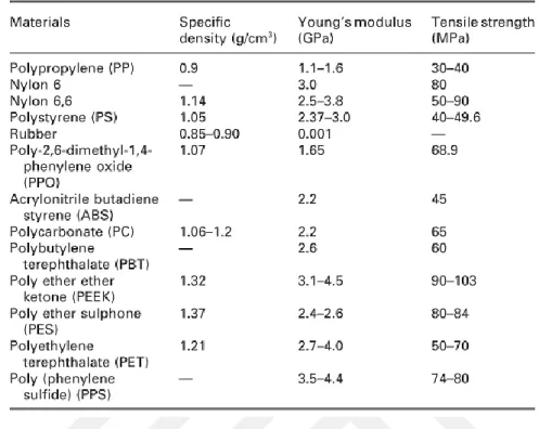
While the contribution of fiber is increasing the strength and stiffness of composite, the matrix is used to transfer the load to the fibers and support them. There are a wide variety of matrix options for SFRP, such as polypropylene (PP), polyamides (PA), acrylonitrile butadiene styrene (ABS) and polyether ether ketone (PEEK). Commonly used matrices and their properties can be found in Table 2.4.
Table 2.4 Properties of commonly used matrices in SFRP (Fu et al., 2009)
The main role of the matrix is to surround fibers to protect them from abrasion and corrosion. Additionally, the matrix binds the fibers and transfer the applied load to fibers. That transfer is necessary to obtain high strength value for the composite. For that purpose, additional coupling agents may be used to enhance the bonding between matrix and fibers. While fibers have low ductility, the matrix has higher ductility which improves the strain at break value of the composite. Properties of matrix change according to the environmental conditions; therefore, the working temperature of the final product shall be taken into consideration. In conclusion, fiber and matrix should be chosen wisely to make up deficiencies of each other.
As mentioned earlier another concern related to SFRP is fiber length and its distribution through the composite. Mostly extrusion and injection molding are used to produce SFRP and these methods include a screw. Rotation of the screw may break the fibers which result in nonuniform fiber length in the composite. Also, the matrix with high viscosity causes poor fiber distribution and the produced composite has lower strength and stiffness values. These fibers have different orientation through the injection direction as well as the thickness. The composite has higher strength and stiffness values in the major orientation direction. In the transverse direction, these values decrease. This orientation is affected by process parameters, mold geometry and gate location. An example of fiber orientation can be seen in Figure 2.6. It is clearly visible that
some fibers make an angle with the flow direction. Orientation also varies through the width of the composite due to flow velocity difference (Fu et al., 2009).
Figure 2.6 Fiber orientation variation from the left side of the composite to the right side (a) left side, (b) middle, (c) right side (Fu et al., 2009)
Yashiro et al. (2011) focused on fiber motion in resin flow. For that purpose, a two-dimensional analysis was performed for SFRP in injection molding. The study showed that flow velocity increases from wall to the middle section and this difference causes fiber motion and this causes unidirectionally aligned rotated fibers. Magnified view of predicted flow is given in Figure 2.7.
Due to the low flow velocity near the wall, fiber #2 and #3 have low velocity. Fiber #1 is positioned near the middle section, consequently; it has a higher velocity. In addition, fiber accumulation and collision happen due to flow velocity difference and this results in randomly oriented short fibers. Therefore, it is hard to predict and simulate the fiber orientation of SFRP.
Production Methods of Composites
There are several methods to produce composites. Production method should be compatible with both matrix and fiber type. Recommended production processes, which are mainly categorized regarding the two types of matrix, are given in Figure 2.8. The first type of matrix is a thermoset which has low viscosity and cures during the process. It forms an intractable solid and it is not possible to reprocess a thermoset by reheating. On the contrary, a thermoplastic has high viscosity and it is processed above its melting temperature. It is possible to reprocess a thermoplastic by reheating above its melting temperature (Campbell, 2010). Production methods are subcategorized regarding the fiber types as continuous and discontinuous. Methods are mainly the same for the same type of fiber types. After deciding on the types of matrix and fiber, a suitable method should be chosen also considering the size and shape of the product, cost and production quantity.
Figure 2.8 Major production methods of composites (Campbell, 2010)
Since SFRP with thermoplastic matrix is the main concern, injection molding as a production method is explained briefly in the following sub-chapter.
2.3.1 Injection Molding
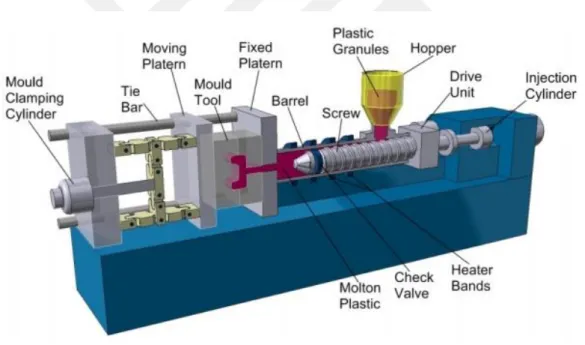
Injection molding is a favored production method for mass production. This method is also applicable to unreinforced plastics. The most commonly processed polymers are polypropylene, nylon or polyamide and polycarbonate. As a working principle polymer pellets are placed in a hopper and transferred by a screw. This motion melts and homogenizes pellets and then melted polymer is injected into a mold. These pellets are either pure polymers or containing short fibers with a length of 1-5 mm (Hull et al., 1996). Components of a typical injection molding machine are given in Figure 2.9.
A screw is an important part of the injection molding process. The screw has two types of motion which are rotation and reciprocation. These motions melt and mix the pellets, which are fed from the hopper, with compression and shear. When the required amount of melt is collected in front of the screw, the screw only reciprocates and injects the melt into the mold.
Figure 2.9 Components of the injection molding machine (RUTLAND Plastic Limited, 2007)
The screw has three zones to feed, melt and meter as shown in Figure 2.10. The feed zone is the first zone to transfer pellets from the hopper to the second zone which is the transition or compression zone. This zone has contact between the barrel and the material. Friction due to the contact helps to melt the pellets. Then homogenized melt is transferred to the third zone which is the metering zone. This zone has the role of supplying the required quantity of molten material for one shot under the pressure. The screw should be designed to obtain the desired
molten material. Breakage of fibers should also be taken into consideration for SFRP during the design procedure.
Figure 2.10 A typical plasticizing screw with zones (Rees, 1994)
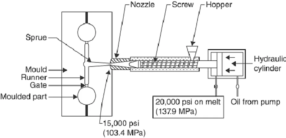
As mentioned above, molten material is injected into a mold cavity. After the material is solidified, it is ejected from the mold and final part is obtained. The mold is mostly metal-machined and contains at least one cavity. The number of cavities may be more depending on the part size and production number. These cavities are fed through channels which are called as a runner. Runners are merged into one channel which is named as sprue and connected to the nozzle. A schematic representation can be seen in Figure 2.11.
Figure 2.11 Schematic representation of the injection unit and mold cavities (Rosato, 1998)
Molds are basically defined as a cold runner and hot runner molds. Since the cooling channels cool down both the runner and the part in the cold runner mold, sprue and runner solidify with the part and they are ejected altogether. An additional process is required to remove the runner
and sprue from the part. If the sprue and runner are kept hot and cooling channels are located around the cavity, the mold is called as hot runner mold. Hot runner mold is more complex; however, it is more efficient since the part is ejected without the runner.
When the molten material flows through more than one direction and reunite, weld line is created at that reunion region. Multiple gates can also result in weld lines. Weld lines are the weak region of the material due to lower strength which is caused by perpendicularly oriented fibers. Mold design should be made to prevent the weld lines or weld lines should be created at less loaded regions (Fu et al., 2009). A study about the effect of weld lines on strength was conducted by Hashemi et al. (1997) and given in Table 2.5.
Table 2.5 Tensile strength of POM and short glass fiber reinforced POM (Hashemi et al., 1997)
Design Considerations for Injection Molded Parts
Even though design and production seem as different processes, both have influences on each other. The design shall be manufacturable; otherwise, it is not effective. During the design process, the manufacturing method should be defined and issues related to the manufacturability should be taken into consideration. In this chapter design considerations for injection molded parts are explained briefly.
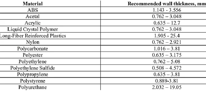
Different from metals, time and temperature have more effects on plastics such as shrinkage and creep. With proper design, it is possible to diminish these effects. In this way, one of the concerns is wall thickness. Heat is one of the inputs in injection molding; however, plastics have lower thermal conductivity values. Therefore, cooling takes more time in thick regions. Since shrinkage occurs during cooling, wall thickness variation results in nonuniform shrinkage
and then warpage. It is strongly suggested to keep the wall thickness uniform or keep the variation as low as possible. Recommended wall thickness value for several plastics is given in Table 2.6. Apart from uniform wall thickness, it recommended to core out the solid shape and obtain shell design. In addition, there should be a gradual transition between the sections with different thickness (Maier, 2009).
Table 2.6 Recommended wall thickness for plastics (Design Guidelines: Plastic Injection. Molding, Proto labs, 2017)
The second concern related to design is corners. Mostly walls make 90 degrees and sharp corner which is unwanted. These sharp corners need to be eliminated due to two reasons. Firstly, the thickness of the sharp corner is more than the wall thickness of the other regions and this causes warpage as mentioned before. Secondly, stress is concentrated on sharp corners and the part is mostly failed in this region. It is advised to radius the internal corner 0.6 to 0.75 times wall thickness. To keep the wall thickness uniform outer corner should be radiused equal to the internal radius plus the wall thickness.
As mentioned before, it is recommended to keep the wall thickness thin and uniform; however, this may not be enough to make the part stiff. At this point, rib comes forward. The rib should have the optimum thickness to avoid buckling under the load. Draft angle needs to be defined to remove the part from the mold without any breakage. Additionally, a fillet radius is necessary to reduce the stress concentration at the connection region of the rib and the wall. Also, the spacing between ribs is important to make the part stiff and eject the part from the mold.
Another possible element used in the design is boss. Boss has a cylindrical shape and it is used as a mounting hole or a spacer. Similar to ribs, the boss should also have a draft angle and a fillet radius. To obtain the required rigidity boss is supported by ribs to make a connection between the boss and base as well as sidewall. Spacing comes forward again to eject the part without any failure (Maier, 2009).
Hybrid Joint
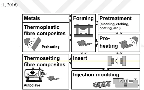
Multi-material design is a new trend these days and the hybrid joint of metal and plastic components is a focus point. Apart from weight reduction, it is possible to obtain more complex shape thanks to injection molding. Previously prepared metal or plastic component is joined with a plastic component with an injection molding process as shown in Figure 2.13 (Drossel et al., 2016).
Figure 2.12 Hybrid component production technology (Geiger et al., 2003))
As Grujicic et al. (2007) mention metals and plastics are widely used in the automotive industry. Due to weight concern usage of plastics is increasing. In this manner, several studies have been conducted to combine the many structural and non-structural components into one single part. The initial successful example of this application was practiced at the front end of Audi A6 in 1996. Sheet steel was combined with PA6 with %30 GF. The main feature of the hybrid structure is that the combination of both materials offers superior properties which individual materials do not have.
Before taking a look at possible methods for hybrid joint, it is good to have an overview of micro-scale polymer-metal adhesion. Ramani and Moriarty (1998), Ramani and Zhao (1997), Ramani and Tagle (1996) conducted a study to see the effects of the following four parameters on the adhesion strength: temperature of the metal specimen, injection machine screw velocity, thickness of overmolded plastics and packing pressure. Among all these parameters metal specimen temperature came forward. It was seen that there is no adhesion between polymer and metal when the metal specimen is not heated. Molten polymer freezes until reaching the metal specimen surface and cannot infiltrate the metal surface. Therefore, it is important to heat the metal specimen around 210℃ (Grujicic et al., 2007).
Moreover, Lucchetta et al. (2011) showed that fiber content has a stronger effect on metal-composite bonding than the surface roughness of metal component. The study was conducted with aluminum and glass fiber reinforced polymer. With increasing fiber content and roughness, mechanical interlocking strengthens and shrinkage reduces as shown in Figure 2.14. High roughness enables the polymer to flow within the cavities on the metal surface and increases the contact surface. This situation also allows glass fibers to have contact with the metal component and higher fiber content makes more fibers contact with the surface of the metal component.
Figure 2.13 Effect of roughness and fiber content on mechanical interlocking (Lucchetta et al., 2011) Hybrid structures can be obtained with fasteners or adhesives after the individual production process of each component. However, this brings additional assembly process and also increases the weight as well as production time (Wang et al., 2016). An alternative approach
to bonding or bolting the components to obtain one single part is an intrinsic hybrid which is defined as the joining of different materials in means of primary shaping or forming one of the materials. The intrinsic joint does not require any assembly process; therefore, it reduces the cycle time and it can be cost saving. No additional process to join the components is required. One of the methods of the intrinsic joint is intrinsic hybridization by deep drawing. Thermoforming process is combined with a metal forming process and continuous carbon fiber reinforced PA6 and an aluminum insert is used as components. Firstly, the polymer is heated up to thermoforming temperature. Then punch moves downwards to form the polymer. At the same time, a tensile load is applied to the metal insert. With tensile load, interlocking elements are created and they are pressed into the molten matrix of the polymer. Finally, the part is cooled down in the die and adhesive bonding is created between the polymer and the metal. Schematic illustration of the process is given in Figure 2.15 (Koch et al., 2016)
Figure 2.14: Process chain of intrinsic hybridization by deep drawing (Koch et al., 2016)
Another approach is intrinsic hybridization during resin transfer molding. This method offers a high production rate. The metal insert is positioned correctly and fiber stacks are placed on the top of each other with the help of jig. Placed fiber stacks over the metal insert create preform and it is placed in RTM mold. The resin is injected into the closed mold and the part is removed after curing. Process chain can be seen in Figure 2.16.
Figure 2.15 Process chain of intrinsic hybridization during resin transfer molding (Koch et al., 2016) Intrinsic hybridization during rotational molding is another option for the hybrid joint. This method is suitable for shafts, pipes and profiles. While hollow dry fiber structure is obtained by braiding, dry filament winding or dry textile pultrusion, the metal component is machined. Then
both components are assembled and placed in the tool. The resin is injected into the tool and the tool is turned. During the rotation at high speed, centrifugal forces help the resin to spread through the dry fiber structure. The process ends when the matrix is cured completely. When the fiber structure is placed inside the metal component, centrifugal force makes hollow structure expand and form better fit.
One another method is intrinsic hybridization during integral tube blowing. This method is used to produce complex shapes. It is the combination of hydroforming and tube blowing. The metal component is manufactured by external and internal high-pressure hydroforming process. At the same time, thermoplastic tape braided preform is produced. After heating, CFRP tube is placed in the metal component and blow molding is performed as seen in Figure 2.17 (Koch et al., 2016).
Figure 2.16 Process chain of intrinsic hybridization during integral tube blowing (Koch et al., 2016) Combination of hydroforming and injection molding is another approach for the hybrid joint. The metal tube is formed by hydroforming with nitrogen inside. The formed metal tube is placed in mold and plastic is injected over it. The cavities created by hydroforming are used as a bonding surface. Final products can be seen in Figure 2.18. In the injection molding process, a non-positive connection is formed because of shrinkage. Since the plastic component has a higher thermal expansion coefficient than the metal component, the plastic component shrinks more. In addition to shrinkage, two types of fitting, which are global form fit and local form fit, are seen between metal and plastic components. Global form fit prevents the tube from shifting and rotating with the help of the shape of the metal tube. Local form fit is related to the surface structure. It is aimed to replace the chemical bonding agent with a surface structure to be cost-effective. PA6 with 60% GF reinforcement, aluminum and steel tubes were used in the study.
The surface is structured with laser structuring, knurling and sandblasting. Experiments showed that the chemical bonding agent has the highest shear and tensile strength limits and it is followed by a laser structured part. However, neither knurling nor sandblasting could not create any undercut on the metal surface for plastic to flow into. This creates only global form fit which carries the tensile load. Therefore, sandblasting and knurling cannot stand high tensile and shear stresses and they are not effective methods for surface structuring (Drossel et al. (2016) and Albert et al. (2015))
Figure 2.17 Process combination of hydroforming and injection molding (Drossel et al., 2016)
Aim of hydroforming is creating a wavy surface for mechanical interlocking. Kießling et al. (2017) have investigated the relation between macroscopic waviness and delamination. Waviness is defined as a ratio of the thickness of wavy surface over wavelength as shown in Figure 2.19. Pull-out simulation is performed to see the effect of interlocking ratio A/λ on the delamination.
Results can be evaluated in three parts. Firstly, the trend is linear up to the first delamination. Although values are close to each other, there is no direct relation between interlocking ratio and force values. When there is a sudden drop in force, it is the point where delamination occurs. Delamination occurs firstly at higher interlocking ratio and results in a sudden increase in displacement. However, higher interlocking ratio experiences less drop in force and the rest of the wavy surface still keeps mechanical interlocking. Therefore, the higher interlocking ratio has more resistance against delamination at higher displacement value.
Material Modelling of Short Fiber Reinforced Composite
Short fiber reinforcement is commonly used to reach higher stiffness and strength values for plastic parts which are produced by injection molding. However, it is hard to predict the mechanical behavior of SFRP due to anisotropy. The orientation of the fibers varies throughout the part depending flow conditions (Robbins et al., 2015). Mold filling speed, viscosity, fiber aspect ratio and fiber concentration have a direct effect on the fiber orientation. Fiber orientation shows a layered nature which means that it varies through the thickness as well as from side to inner core as mentioned before. Therefore, a proper understanding is necessary to estimate the mechanical properties of SFRP. There is some commercial software to estimate the fiber orientation and after mechanical properties. Data exchange procedure is shown in Figure 2.20
Moldflow is a commonly used software to predict the fiber orientation. It also gives feedbacks about gate position, filling time, part quality, shrinkage etc. After the CAD model is imported to Moldflow, it simulates the flow considering gate position, runner system and process parameters. Setup and result of this simulation can be seen in Figure 2.21. The result of this simulation is exported to perform further analysis. Autodesk Moldflow Structural Alliance or DIGIMAT is used to process the data. Processed data is available to be used in ABAQUS or ANSYS for structural analysis with anisotropic material behavior. (Kulkarni et al., 2012)
Figure 2.20 (a) Moldflow setup, (b) Fiber orientation plot (Kulkarni et al., 2012)
Kulkarni et al. (2012) conducted a study to show the variation of the mechanical properties regarding material behavior. PEEK plate with 30% CF is used as a material and Moldflow, Autodesk Moldflow Structural Alliance and ANSYS are used to simulate the flow and perform the structural analysis. Analysis with the same boundary conditions are performed for isotropic, transversely isotropic and orthotropic material behavior individually and the results were compared with the experimental results. As seen in Figure 2.22 the isotropic results are approximately 50% off regarding the experimental results since the assumption of equal stiffness in all direction is non-realistic. Transversely isotropic material model is a more accurate approach than the isotropic model but there is still large deviation. Orthotropic model, which assumes different stiffness in all three directions, has the closest results to the real case.
Figure 2.21 Comparison of the material models (Kulkarni et al., 2012)
In finite element analysis, computation time has also importance. It is suggested that there should be at least 3 elements through the thickness; however, this results in too many elements. Additionally, it is hard to model a complex geometry with shell elements. 3D tetrahedral elements can be used as an alternative. When many parts are considered in FEA, coarse tetrahedral meshes with 2 elements through the thickness can be used in order to keep the finite element model size smaller. Comparison of computation time in terms of material modeling is given in Table 2.7 (Schmidt, 2013).
Schmidt (2013) performed analyses with different material modeling. Table 2.8 shows the comparison of stress results obtained in this study. The anisotropic linear solution is taken as a reference and the results are given in percentage of the reference. It is seen that the isotropic model underestimates stress value with a difference of approximately 30%. It is also mentioned that the anisotropic material model gives the most realistic results with the most computation time.
Table 2.8 Stress results for different calculation methods (Schmidt, 2013)
A similar approach to Schmidt in terms of meshing is mentioned in NX FEM Basic Training Manual. It is hard to mesh a complex geometry with shell elements. Only tetrahedral elements as 3D elements are available for an automatic meshing which is time-saving. There are two options under the tetrahedral elements which are CTETRA4 element with linear element approach and CTETRA10 element with parabolic element approach. CTETRA4 is suggested to check the simulation generally. Stress and displacement values are not trustable. On the other hand, CTETRA10 gives sufficient exactness with slower computation. It is favored for good results with low meshing effort. In Figure 2.23 comparison of manual calculation and FEA is given. CTETRA10 gives almost the same results with manual calculation; whereas, results of CTETRA4 is not precise. Moreover, smaller element size mostly provides higher precision (NX FEM Basic Training, Daimler Engineering Training, 2017).
Figure 2.22 Comparison of tetrahedral elements in terms of element size and element type (NX FEM Basic Training, Daimler Engineering Training, 2017)
3
Design and Finite Element Analysis
The Real Case Scenario – Truck Fender Components
A fender is used to protect the tire from the environmental effects such as mud or gravel. The fender consists of four different pieces which have approximately the total weight of 10 kg as seen in Figure 3.1.
Figure 3.1 Truck fender and its components
The fender is carried by two steel tubes which are made of steel EN 10305-2, 1.0580 and each one is 2.8 kg. There is a cylindrical cavity as an assembly interface on the fender to assemble it with a tube. That cavity makes a tight fit with the tube and distributes the load on the tube. The fender and the tube are mounted each other with M10 bolts. Another component, which is named as a console, is used to fix the tube to the chassis of the truck. The console is made of steel with a specification of EN 10025-2 1.0553+N and it is also forged. Its weight is approximately 1.7 kg. The console and the tube are assembled by friction welding which is an expensive process. The console is fixed to the chassis with three M16 bolts with an applied torque of 225±75 Nm. Dimensions of the console and the tube are given in Figure 3.2.
Figure 3.2 Dimensions of the console and the tube
Mercedes-Benz Turk produces the towing part of the truck which has minimum two fenders. This makes minimum four tubes and four consoles for each truck. The trailer part is added according to customer’s request; therefore, its components may vary and it is not considered in this study.
There are no directly defined requirements for fender components; however, environmental requirements for the fender is given below:
• Temperature: from -40ºC to +85ºC • Humidity: 0 to 100%
• Seawater resistant • UV radiation resistant
The same environmental requirements are also considered as valid for the truck fender components. Additionally, each console carries one tube and half of the fender as weight which is approximately 8 kg. Therefore, especially the console shall be durable against high vibration and bending forces due to the rough road. Although tensile stress limit of PA6 with 30% GF is around 100 MPa at the datasheet, this limit is taken as 30 MPa at Mercedes-Benz Turk for safety and material modeling reasons. Therefore, stress value shall be lower than 30 MPa at the
final design. Since the strength limit of SFRP is lower than steel, initial failure is expected on the console.
Development of metal-composite hybrid joint is aimed in this study. After consideration of the current components, it is decided to change the material of the console from steel to composite. This idea brings three subcases with itself. Firstly, the composite console should be strong enough to resist against 225±75 Nm applied torque to tighten the bolts. Secondly, a hybrid joint should be developed to connect hollow parts which are the console and the tube. Lastly, this developed joint should be reinforced with a proper design. In summary, product development with an applicable joining method is the main point of this case study.
Initial Concept Study
At the previously performed studies about the development of hybrid joint for hollow parts, hydroforming is widely used to create a wavy surface on the hollow part. This wavy surface is used to build a connection surface and mechanical interlocking after injection molding. The idea of the hybrid joint, which is explained in this thesis, is inspired by these studies. Instead of hydroforming and uneven wavy surface, identical grooves with exact dimensions are used to develop a hybrid joint between metal and composite. Composite part is produced by overmolding and a tube with grooves is used as an insert during injection molding.
Considering the restrictions of design, which are the gap below the console and keeping the position of connection holes same, first concept design of the console is made as shown in Figure 3.3. Further improvements are performed on this initial design considering manufacturability and analysis result.
New design steps and design improvements with respect to FEA results are explained in the following chapters.
Design and Finite Element Analysis: Connection Holes
Connection holes are used to mount the console to the chassis with three M16 bolts. According to the standard, M16 bolt shall be tightened with a torque of 225±75 Nm and this torque causes maximum 52 kN load on each hole. Therefore, the new design should be resistant against compressive load of 52 kN. To simulate this compressive load, a cylindrical part with 32 mm radius and 2 mm thickness and a block are drawn to represent a washer and a chassis, respectively as seen in Figure 3.4. 52 kN force is applied to each washer individually. Results are compared in terms of displacement to obtain the adequate design for the connection holes.
Figure 3.4 Simulation of compressive load
First compression analysis is performed with initial concept design to have an overview of the load effect. PA6 with 30% GF is used as material at each analysis. The console and the chassis are fixed to each other to prevent the separate movement of each part. Friction is defined between washers and the console. The obtained result is given in Figure 3.5. The displacement value is 0.824 mm and connection holes lean outward due to one-sided support. From this result, it is seen that composite material cannot resist against 52 kN load by itself and circumferential support is required for proper and even support.
Figure 3.5 Compression analysis result of initial concept design (10 times magnified)
As mentioned above, the connection holes should be reinforced to decrease the compressive displacement due to the applied torque. In the market, BigHead offers metal reinforcement to reinforce composite and holes. Similar to this idea, the application of metal insert at the connection holes comes forward to decrease the displacement value. For this purpose, steel insert with a thickness of 3 mm is added to the design. Idea is placing these inserts into the mold and injecting the composite material into the mold. Additional analysis is performed to see the effect of the metal insert on the displacement and to investigate the necessity of adhesive between the insert and the composite. Result of the analysis is given in Figure 3.6. In the analysis, three different cases are simulated. A connection hole without a metal insert is taken as a reference. Additionally, other two connection holes are reinforced with a metal insert. For one of these holes, it is assumed that adhesive is applied; therefore, an insert and composite are glued to each other. For the other hole, only friction is considered with a friction coefficient of 0.3. Without a reinforcement, connection hole is compressed approximately 0.8 mm. Existence of a metal insert reduces this value directly to 0.2 mm. When adhesive is applied on the metal insert, displacement level decreases to 0.1 mm. Although adhesive application results in low displacement value, it brings additional process and cost. Therefore, it is a better choice to reinforce the connection holes with a proper design to eliminate the usage of adhesive. From
this point, the metal insert with frictional contact is included in the design for further improvements.
Figure 3.6 Effect of a metal insert on compressive displacement (10 times magnified)
As given in Table 2.6, recommended wall thickness for nylon or PA6 is 3 mm. The initial concept design is redesigned to have uniform wall thickness considering the recommended thickness value. To prevent outward leaning, circumferential support for connection holes are added and this results in two different designs which are given in Figure 3.7 (a) and (b). In design (a), 8 gussets are distributed evenly around the connection holes. Under 52 kN load, this design compresses approximately 0.1 mm. As a further improvement, wall structure is built around the console considering the gap below the console to increase rigidity. Connection holes are supported with both gussets and ribs. This design enhances the compression resistance and decreases the displacement value to 0.08 mm. Addition of net-shaped ribs and gussets around the connection region of the console with the tube ends up with more rigid design as seen in Figure 3.7 (c). This design improves the compression resistance at a very small scale; nevertheless, the rigid structure offers better tensile and bending resistance.
Figure 3.7 New designs (a) circumferential support with gussets, (b) wall support with gussets and ribs, (c) wall support with additional net structure
Displacement less than 0.1 mm is acceptable; therefore, design (b) is taken as a base design to make further improvements to satisfy other requirements. The same analysis will be performed for the final design.
Design and Finite Element Analysis: Development of Hybrid Joint
Development of hybrid joint between the composite console and the metal tube is the main concern of this thesis. As mentioned before, similar studies combine injection molding and pipe surface forming such as hydroforming. Wavy surface of a pipe is used to create mechanical interlocking between two parts. A similar approach is used to assemble the console and the pipe. Instead of wavy surface, exactly defined grooves are used for the purpose of hybrid joint. Two types of grooves, which are ball end groove and U groove, are used to compare mechanical interlocking ability. Each groove has the same depth of 1.5 mm; whereas, width value varies. Groove types are given in Figure 3.8.
Figure 3.8 Groove types: (a) ball end groove, (b) U groove
Although there is no direct tensile load on the pipe, tensile test is performed under the load of 1000 N. The reason behind of this load is explained in Chapter 4. The console is fixed from connection holes and 1000 N load is applied at the tip of the tube. Friction coefficient of 0.3 is defined at the mutual surface of the pipe and the console. There is no adhesive applied on the surface. The initial aim is to compare the groove shape in terms of displacement and stress. Later, the effect of the groove width will be discussed.
Figure 3.9 Tensile test to compare the mechanical interlocking ability of different groove types
Tensile test analysis is performed for a tube with ball end groove and U groove to compare the groove types. Each groove has the same width of 5 mm and a depth of 1.5 mm. Results are given in Figure 3.10. According to the analysis results, ball end groove ends up with more than 50% less tensile displacement compared with U groove. Although the width and depth of the grooves are same, groove sections are different. Delamination performance of these two types of grooves can be partly compared with the study performed by Kießling et al. (2017) which is mentioned in Chapter 2.5. According to the performed study, delamination occurs at lower forces for higher A/λ ratio. In our case, this ratio is same for both groove types; however, a similar approach can be used to investigate the delamination phenomena. When A, which can be considered as depth value, is taken as a constant value, smaller λ value, which is wavelength, creates steeper groove profile with higher A/λ ratio. Profile of U groove is steeper than the profile of ball end groove and any shift during delamination ends up with a higher rate of separation. Therefore, U groove causes higher displacement under the same loading condition. Apart from higher displacement value, U groove has also higher stress on the groove filling region. Maximum stress limit is set as 60 MPa to see the difference between groove types clearly as shown in Figure 3.10. While ball end groove has stress value mostly lower than 30 MPa, U groove is exposed to stress higher than 60 MPa which is out of the requirements. This analysis shows that ball end groove is more applicable to our case. Further investigations are based on ball end groove with different width values.
Figure 3.10 Stress and displacement values of groove types (10 times magnified)
Similar tensile test analyses are performed for ball end grooves with different width values. The tube has always six grooves with a depth of 1.5 mm. Width value represents the diameter of the grooving tool. Since the depth of the groove is fixed, groove width on the tube is not same with tool diameter. The diameter of the grooving tool and groove width are represented as w and wreal, respectively. Types of ball end groove considered in this study are given in Figure 3.11.
Figure 3.11 Types of ball end groove
Goal of these analyses is to see the effect of groove width on mechanical interlocking. Kießling et al. (2017) summarize the result of his study in one graph as given in Figure 2.19. When the linear part of that graph is considered, it is seen that A/λ ratio and displacement at a fixed load are not completely correlated. A/λ ratio from less displacement to high displacement is 0.5, 0.63 and 0.55, respectively. In our case A is same for each type of groove and λ can be considered as width value. In this way, three ratios mentioned above show that the highest width value results in less displacement; however, lower width values and their displacement do not follow this trend. The trend of this graph is that displacement increases with increasing width and then decreases. The result of the analysis, which is given in Figure 3.12, is partly similar to the result of Kießling. Increasing the width value initially decreases displacement. At one point this trend becomes reversed and displacement increases with increasing width value. Analysis results show that Type 4 has the lowest displacement value with a groove width of 5.745 mm. From 3 mm width to 5.7 mm width, displacement value falls by half. After a width of 5.7 mm, displacement slightly increases; however, displacement variation is not as large scale as width value lower than 5.7 mm. Analysis results can be interpreted as that increase in width value decreases tensile displacement. However, there is an optimum value in between which provides better mechanical interlocking.
Figure 3.12 Effect of groove width on tensile displacement
Design and Finite Element Analysis: Reinforcement of Hybrid Joint
At the previous subsection, the optimized solution for the hybrid joint is chosen considering mechanical interlocking under tensile load. However, the truck fender components are exposed to vertical loading due to the weight of the fender and rough road conditions as well as horizontal loading due to acceleration and brake. Therefore, the hybrid joint needs to be supported against horizontal and vertical loading which are basically bending forces. According to the durability requirements defined by Mercedes-Benz Turk, the maximum load applied to the tube is 1000 N in the vertical direction. In this section, it is aimed to obtain a design which has stress value lower than 30 MPa under 1000 N and minimize the displacement at the tip point of the tube which has the maximum displacement.
A console is mounted to a chassis with M16 bolt which has a head diameter of 32 mm. Additionally, a wrench, which has an outer diameter of 40 mm, is used to tighten the bolts. Therefore, some regions on the console shall be free for a wrench as seen in Figure 3.13. These free regions are taken into consideration in the design phase. Two different main designs are made and they are modified regarding the analysis results. Firstly, designs are compared regarding the displacement value and then stress value is taken into account.
0,0500 0,0600 0,0700 0,0800 0,0900 0,1000 0,1100 0,1200 0,1300 3,000 4,583 5,196 5,745 6,245 7,141 Te n si le d is p la ce men t Groove width
Figure 3.13 Available space for reinforcement on the console
First design group is reproduced from the concept design as given in Figure 3.14 (a). Available space is used to place gussets to support the cylindrical part circumferentially. In the concept design, gussets are placed randomly and thickness is 6 mm which is out of recommended wall thickness for PA6. In the first reproduced design thickness is lowered to 3 mm and five gussets are placed at each side. Under 1000 N distributed load on the tube, maximum displacement is 9.2 mm. To reduce the displacement small gussets are added to the upper side of the cylinder considering the free space required. This addition results in 8.1 mm displacement which means that gussets at the upper region have a significant effect on the displacement.
Second design group given in Figure 3.14 (b) is based on the boundaries of the required free space. Boundaries are used to create outer ribs and more ribs are added to the inner region. This type of reinforcement ends up with 5.9 mm displacement which is much lower than the displacement value of the first design group. Due to its appearance, it could not receive approval and another design is reproduced. Instead of the partial outer wall, another cylindrical wall is formed and ribs are used to support the cylindrical part with the hybrid joint. Additional gussets are added around the outer cylindrical wall to have a more rigid design; however, displacement value for this design is 7.6 mm which is higher than the main design.
Figure 3.15 Stress values after bending analysis
Up to this point, designs are compared regarding their maximum displacement value. Stress analysis is performed for the initial and final design of each design group and result are given in Figure 3.15. At first sight, it is seen that high stress is concentrated on the tip point of gussets located on the upper and lower sides. Stress limit is set to 60 MPa in order to make comparison easily. When the initial design of the first design group is investigated, it has relatively less high stress concentration compared with the final design. The main reason of this difference is thickness. Thickness is lowered from 6 mm to 3 mm and this makes the part less rigid. As seen in Figure 3.15, gussets at the upper side have tensile stress over the limit and it needs to be lowered. As an idea, an additional rib is added at the backside of the console at the projection
of the gusset tips in order to distribute the stress; however, it does not make any improvement in this way.
Final design of each design group will be considered in the next section in terms of manufacturability and design improvement.
Figure 3.16 Effect of the additional rib
Design Improvements
At the reached point there are two different design alternatives to replace the console. Both designs are shared with Assan Hanil to discuss their manufacturability. One feedback is related to thickness value. According to their experience, it is possible to produce a PA6 part with 4 mm thickness by injection molding. Increase in thickness makes the part more rigid and this results in less displacement. Thickness is increased to 4 mm as a part of the improvement. Another feedback is about depth/width ratio. This ratio should be maximum five in order to remove the injected part from the mold without any failure. This feedback affects the final designs in two ways as shown in Figure 3.17. Firstly, ribs on the backside have a ratio of 9.5. Width of these ribs should be elongated considering the dimension of the console and other parts on the chassis. This effect is valid for each design. Secondly, depth/width ratio of the design with the second cylindrical wall should be increased. The current design has a ratio of