COMPUTATIONAL ANALYSIS OF COMPLICATED
METAMATERIAL STRUCTURES USING MLFMA AND
NESTED PRECONDITIONERS
¨
O. Erg ¨ul
1,2, T. Malas
1,2, C
¸ . Yavuz
2, A. ¨
Unal
2, L. G ¨urel
1,21Department of Electrical and Electronics Engineering
2Computational Electromagnetics Research Center (BiLCEM)
Bilkent University, TR-06800, Bilkent, Ankara, Turkey E-mail: [email protected]
fax: +90-312-2905755
Keywords: Metamaterials, electromagnetic scattering,
electric-field integral equation, multilevel fast multipole algorithm, nested preconditioners.
Abstract
We consider accurate solution of scattering problems
involving complicated metamaterial (MM) structures
consisting of thin wires and split-ring resonators. The scattering problems are formulated by the electric-field integral equation (EFIE) discretized with the Rao-Wilton-Glisson basis functions defined on planar triangles. The resulting dense matrix equations are solved iteratively, where the matrix-vector multiplications that are required by the iterative solvers are accelerated with the multilevel fast multipole algorithm (MLFMA). Since EFIE usually produces matrix equations that are ill-conditioned and difficult to solve iteratively, we employ nested preconditioners to achieve rapid convergence of the iterative solutions. To further accelerate the simulations, we parallelize our algorithm and perform the solutions on a cluster of personal computers. This way, we are able to solve problems of MMs involving thousands of unit cells.
1 Introduction
Since they were firstly proposed theoretically in 1968 [15], metamaterials (MMs) have attracted a great amount of interest in the scientific community due to their useful electromagnetic properties. Real-life MM structures are usually constructed by embedding unit cells, such as thin wires (TWs) and split-ring resonators (SRRs), into some host media to obtain effective negative permittivity and permeability. There have been many experimental studies on developing novel structures to further enhance the desired properties and improve the practicability of MMs [12]. In this manner, it is desirable to support the experimental works with the simulation environments
y
x
z
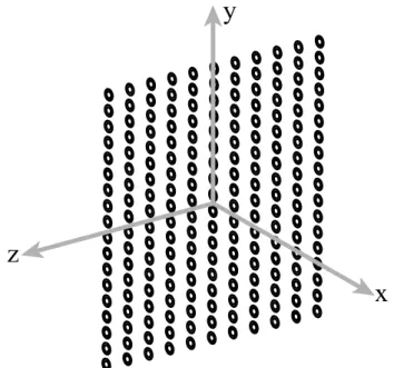
Fig. 1: A metamaterial structure consisting of 18×11 SRRs. based on accurate mathematical formulations of physical phenomena related to MMs. This way, it becomes possible to investigate complicated MM structures before their actual realizations.
In this paper, we present our efforts to develop a sophisticated simulation environment for the accurate analysis of MMs. Our computational approach is based on the formulation of scattering problems involving three-dimensional conducting surfaces with the electric-field integral equation (EFIE) [11]. Without using any homogenization technique, we accurately model the electromagnetic interactions involved in three-dimensional MM structures with arbitrary geometries. As an example to those structures, Fig. 1 depicts an SRR array, which is constructed by the arrangement of 18 × 11 SRRs. The surfaces with zero thickness are discretized
by using planar triangles, on which the Rao-Wilton-Glisson (RWG) basis functions are defined to expand the surface current density [13]. Discretization of EFIE leads to dense matrix equations, which can be solved iteratively with the accelerated matrix-vector multiplications by the multilevel fast multipole algorithm (MLFMA) [14]. Since EFIE produces ill-conditioned matrix equations that are difficult to solve iteratively [6],[7] and MM structures usually present numerical resonances that further inhibit quick convergence of the iterations [3], we employ robust preconditions to perform the simulations efficiently. We consider a nested preconditioning technique based on an approximate MLFMA (AMLFMA) obtained by reducing the sampling rate of the original MLFMA for improved efficiency [9]. To further accelerate the simulations, we parallelize our solver and perform the solutions on a cluster of personal computers. By constructing a robust simulation environment based on diverse components, such as integral-equation formulations, iterative solvers, nested preconditioners, and parallel MLFMA, we are able to perform accurate and efficient simulations of MMs involving thousands of unit cells.
2 Multilayer Metamaterial Structures
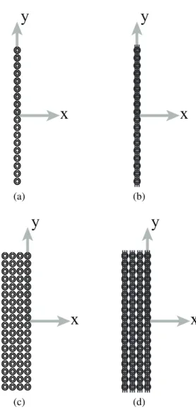
In this paper, we perform simulations of multilayer MM structures consisting of SRRs and TWs. Fig. 2(a) presents a side view of the 18×11 SRR array in Fig. 1. Around the resonance frequency of SRRs, the transmission through this array is expected to decrease significantly due to the effective negative permeability introduced in the medium. The unit cell dimensions of the SRRs are in the order of microns to obtain a resonance around 100 GHz [5]. When the SRR array is combined with TWs as described in [8], we obtain the composite metamaterial (CMM) structure depicted in Fig. 2(b). Dimensions of the TWs are compatible with the dimensions of the SRRs and they exhibit effective negative permittivity in a wide range of frequencies including 100 GHz. Consequently, the CMM structure in Fig. 2(b) show double-negative property around 100 GHz. Finally, in order to increase the bandwidth of the resonance effects, we construct multilayer MM structures by stacking the arrays in Figs. 2(a) and 2(b) as depicted in Figs. 2(c) and 2(d) [4].
3 Formulations by EFIE
By the discretization of EFIE for the solution of complicated MM structures, we obtain N × N dense matrix equations
(in frequency domain using phasor notation with the e−iwt
convention) as N X n=1 ZE mnan= vmE, m = 1, ..., N, (1)
where the matrix elements and the elements of the exciation
y
x
y
x
(a) (b)y
x
y
x
(c) (d)Fig. 2: (a) Side view of the 18×11 SRR array in Fig. 1. (b) CMM structure obtained by combining the 18×11 SRR array with TWs. (c) 4-layer SRR array obtained by stacking 18×11 SRR arrays. (d) 4-layer CMM structure obtained by stacking 1-layer CMM arrays.
vector are derived as
ZE mn= ik Z Sm drtm(r) · Z Sn dr0³I −∇∇0 k2 ´ g(r, r0) · b n(r0) (2) and vE m= − 1 η Z Sm drtm(r) · Einc(r), (3)
respectively. In (2) and (3), Sm and Sn symbolize the spatial
supports of the mth testing function tm(r) and nth basis
function bn(r0), respectively. We apply a Galerkin scheme
and choose the basis and testing functions as RWG functions defined on planar triangles [13]. In addition, in (2) and (3),
k = w√µ² is the wavenumber associated with the host
medium, η = pµ/² is the wave impedance, Einc(r) is the
incident electric field due to the external sources, and
g(r, r0) = eikR
4πR ³
denotes the homogeneous-space Green’s function. As it is commonly used in experimental setups [5], we choose the relative permittivity of the host medium as 4.8.
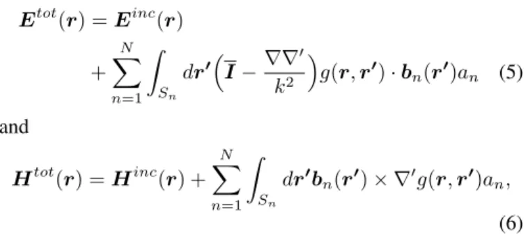
Finding the coefficients an in (1), we obtain the
near-zone electric and magnetic fields as
Etot(r) = Einc(r) + N X n=1 Z Sn dr0³I −∇∇0 k2 ´ g(r, r0) · b n(r0)an (5) and Htot(r) = Hinc(r) + N X n=1 Z Sn dr0bn(r0) × ∇0g(r, r0)an, (6)
respectively, where Hincis the incident magnetic field. Then,
the total average power density is evaluated as
Ptot av(r) = 1 2Re n Etot(r) × [Htot(r)]∗o, (7)
where we consider the real part of the complex Poynting vector. Finally, the power transmission at an observation point
r can be defined as T (r) = Pavtot(r) Pinc av (r) , (8) where Pavinc= 1 2Re n Einc(r) × [Hinc(r)]∗ o (9) is the incident average power density.
4 Iterative Solutions by MLFMA
The matrix equation in (1) is solved iteratively, where the matrix-vector products are accelerated by MLFMA. The fundamental idea in MLFMA is to replace the element-to-element interactions with cluster-to-cluster interactions in a multilevel scheme. This computational scheme relies on the factorization of the Green’s function, which is valid only for basis and testing functions that are far from each other. In general, MLFMA splits the MVMs as [14]
Z · x = ZN F · x + ZF F · x, (10)
where the near-field interactions denoted by ZN F are
calcu-lated directly and stored in memory, while the far-field
interac-tions (ZF F) are computed approximately in a group-by-group
manner using cubic clusters. The accuracy of MLFMA is adjusted by a parameter called truncation number determined by the excess bandwidth formula [2] as
Tl≈ kdl+ 1.8(n0)2/3(kdl)1/3 (11)
for each level l = 1, 2, ..., lmax, where dl is the size of
the clusters in level l, k is the wavenumber, and n0 is the
desired digits of accuracy. The truncation number corresponds to the number of harmonics considered in the translation operators and it is also related to the number of samples
(Sl) for the radiated and incoming fields of the clusters, i.e.,
Sl= 2(Tl+ 1)2. Considering the worst-case scenario in (11),
the size of clusters dl equals to
√
3al, where al is the length
of the edge of the cubic clusters.
5 Nested Preconditioners
EFIE usually produces ill-conditioned matrix equations that are difficult to solve by an iterative algorithm [6],[7]. In addition, MM structures usually present numerical resonances, which further inhibits a quick convergence without preconditioning [3]. To obtain a convergence
in a reasonable number of iterations, we employ
enhanced preconditioning techniques that are also
convenient for MLFMA implementations. For example, we consider preconditioners based on incomplete LU (ILU) factorization [10] or sparse approximate inverse (SAI) of the near-field matrix [1]. Although these preconditioners provide efficient solutions for ordinary frequencies, formulations at resonance frequencies lead to very ill-conditioned matrix equations, which need further information than that provided by the near-field matrix for a convergence. Then, we consider a two-level preconditioning technique based on AMLFMA obtained by reducing the sampling rate of original MLFMA for improved efficiency [9].
In a nested preconditioning scheme, solutions of the preconditioner equation are also performed iteratively (inner iterations). Matrix-vector multiplications of the inner iterations are performed by AMLFMA using the reduced truncation numbers determined by
Tlapp= Tmin+ af(Tl− Tmin), (12)
where Tl represents the original truncation numbers used by
MLFMA, Tminis the minimum truncation number, and af is
an approximation factor. Our experiments show that choosing
af = 0.2 provides an efficient preconditioner with a sufficient
approximation of the full matrix-vector multiplication. Finally, the inner iterations are further accelerated by a conventional preconditioner such as SAI. Using an AMLFMA with the truncation numbers in (12), the additional cost during the setup is negligible; only a second set of translation operators is required. On the other hand, we are able to accelerate the iterative solutions significantly, since we employ a very strong preconditioner, which approximates the original matrix more than those using only the near-field interactions.
6 Results
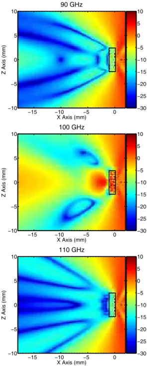
Fig. 3 presents the results for the 4-layer SRR array in Fig. 2(c), where the power transmission is plotted at various frequencies, i.e., 90 GHz, 100 GHz, and 110 GHz. The transmission is calculated at different points in the y = 0 plane and the area occupied by the SRR array is represented by rectangles in the plots. The excitation is a Hertzian dipole oriented in the y direction as also indicated in
90 GHz X Axis (mm) Z Axis (mm) −15 −10 −5 0 −10 −5 0 5 10 −30 −25 −20 −15 −10 −5 0 5 10 100 GHz X Axis (mm) Z Axis (mm) −15 −10 −5 0 −10 −5 0 5 10 −30 −25 −20 −15 −10 −5 0 5 10 110 GHz X Axis (mm) Z Axis (mm) −15 −10 −5 0 −10 −5 0 5 10 −30 −25 −20 −15 −10 −5 0 5 10
Fig. 3: Power transmission for the 4-layer 18×11 SRR array depicted in Fig. 2(c) at various frequencies.
the plots by dots and the transmission region is on the left of the array. At 90 GHz and 110 GHz, the power transmission through the SRR array is almost unity, which corresponds to 0 decibels (dB). On the other hand, around the resonance frequency (100 GHz), the transmitted power drops dramatically due to the shadowing effect of the SRRs. In other words, negative effective permeability is stimulated in the medium and the transmitted power is blocked at 100 GHz. Fig. 4 presents the power transmission for the 4-layer CMM array depicted in Fig. 2(d). As opposed to the
90 GHz X Axis (mm) Z Axis (mm) −15 −10 −5 0 −10 −5 0 5 10 −30 −25 −20 −15 −10 −5 0 5 10 100 GHz X Axis (mm) Z Axis (mm) −15 −10 −5 0 −10 −5 0 5 10 −30 −25 −20 −15 −10 −5 0 5 10 110 GHz X Axis (mm) Z Axis (mm) −15 −10 −5 0 −10 −5 0 5 10 −30 −25 −20 −15 −10 −5 0 5 10
Fig. 4: Power transmission for the 4-layer CMM structure depicted in Fig. 2(d) at various frequencies.
SRR array, we observe that the CMM structure blocks the fields at 90 GHz and 110 GHz; this is mainly due to the negative effective permittivity introduced by the TWs. On the other hand, the multilayer structure becomes transparent at 100 GHz corresponding to the resonance frequency of the SRRs. Because, at this frequency, both the effective permittivity and permeability stimulated in the medium become negative.
The number of unknowns for the 4-layer SRR and CMM structures in the previous examples are 64,944 and 110,304,
85 GHz X Axis (mm) Z Axis (mm) −15 −10 −5 0 −10 −5 0 5 10 −30 −25 −20 −15 −10 −5 0 5 10 100 GHz X Axis (mm) Z Axis (mm) −15 −10 −5 0 −10 −5 0 5 10 −30 −25 −20 −15 −10 −5 0 5 10 110 GHz X Axis (mm) Z Axis (mm) −15 −10 −5 0 −10 −5 0 5 10 −30 −25 −20 −15 −10 −5 0 5 10
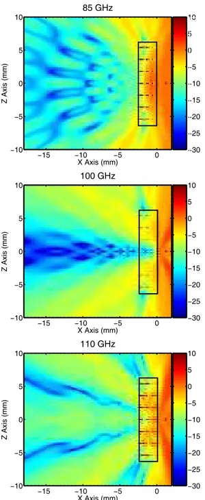
Fig. 5: Power transmission for a 20×51×29 SRR array at various frequencies.
respectively. As an example to the simulation of larger MM structures, Fig. 5 presents the results of scattering problems involving a 20×51×29 SRR array discretized with 2,425,560 unknowns. Solution of this problem at a single frequency requires about 156 minutes by employing MLFMA parallelized into 64 processes on a cluster of Intel Xeon 5355 processors connected via an Infiniband network. Fig. 5 presents power transmission plots at 85 GHz, 100 GHz, and 110 GHz. In addition to the shadowing at 100 GHz, we observe that the transmitted power is also blocked at 85 GHz and 110 GHz, as a result of the extended bandwidth of the
y
x
x
-z
-z
y
(a) 85 90 95 100 105 110 −20 −10 0 10 Frequency (GHz) Transmission (dB) Ordered Disordered (b)Fig. 6: (a) Disordered MM structure obtained by randomly shifting the columns of the 18×11 SRR array in Fig. 1. (b) Power transmission at (-1.25 mm, 0 mm, 0 mm) for the ordered and disordered SRR arrays as a function of frequency. resonance with the increased number of layers. The plots in Fig. 5 also shows that the value of the power transmission varies significantly with respect to position. These variations may not be calculated correctly by using homogenization techniques and other simplified methods.
Finally, we consider a disordered MM structure involving misaligned unit cells as depicted in Fig. 6(a). Columns of the 18×11 SRR array are shifted randomly (in the z direction) to simulate possible defects during the fabrication. In Fig. 6(b), the power transmission at (x, y, z) = (-1.25 mm, 0 mm, 0 mm) is plotted as a function of frequency for the disordered and original (ordered) SRR arrays. We observe that the disordering in Fig. 6(a) affects the transmission properties; the resonance is shifted to a lower frequency and the minimum transmission value is increased. In general, the power transmission is affected differently depending on the disordering scheme [4] and a meaningful investigation of disordered MM structures requires an accurate calculation of complicated interactions between the unit cells. By using a full-wave electromagnetic solver, we perform accurate simulations of disordered MMs.
7 Conclusion
By constructing a sophisticated simulation environment based on diverse components, such as integral-equation formulations, iterative solvers, nested preconditioners, and parallel MLFMA, we are able to perform accurate and efficient simulations of MMs involving thousands of unit cells discretized with millions of unknowns. Transmission properties of SRR and CMM arrays, including disordered structures, are investigated accurately in order to confirm the theoretical findings on practical cases.
Acknowledgements
This work was supported by the Scientific and Technical Research Council of Turkey (TUBITAK) under Research Grant 105E172, by the Turkish Academy of Sciences in the framework of the Young Scientist Award Program
(LG/TUBA-GEBIP/2002-1-12), and by contracts from
ASELSAN and SSM.
References
[1] B. Carpentieri, I. S. Duff, and L. Giraud, “Experiments with sparse preconditioning of dense problems from elec-tromagnetic applications,” CERFACS, Toulouse, France, Tech. Rep. TR/PA/00/04, 1999.
[2] W. C. Chew, J.-M. Jin, E. Michielssen, and J. Song, Fast
and Efficient Algorithms in Computational Electromag-netics. Boston, MA: Artech House, 2001.
[3] ¨O. Erg¨ul, A. ¨Unal, and L. G¨urel, “Accurate modeling of
metamaterials with MLFMA,” in Proc. European
Con-ference on Antennas and Propagation (EuCAP), 350094,
2006.
[4] ¨O. Erg¨ul, C¸. Yavuz, A. ¨Unal, and L. G¨urel,
“Investiga-tion of various metamaterial structures using multilevel fast multipole algorithm,” in Proc. IEEE Antennas and
Propagation Soc. Int. Symp., 2007, pp. 1845–1848.
[5] M. Gokkavas, K. G¨uven, I. Bulu, K. Aydın, R. S. Penciu,
M. Kafesaki, C. M. Soukoulis, and E. ¨Ozbay,
“Experimen-tal demonstration of a left-handed metamaterial operating at 100 GHz,” Phys. Rev. B., vol. 73, no. 193103, 2006.
[6] L. G¨urel and ¨O. Erg¨ul, “Comparisons of FMM
imple-mentations employing different formulations and iterative solvers,” in Proc. IEEE Antennas and Propagation Soc.
Int. Symp., vol. 1, 2003, pp. 19–22.
[7] L. G¨urel and ¨O. Erg¨ul, “Extending the applicability of the
combined-field integral equation to geometries containing open surfaces,” IEEE Antennas Wireless Propagat. Lett., vol. 5, pp. 515–516, 2006.
[8] L. G¨urel, ¨O. Erg¨ul, and A. ¨Unal, “Accurate analysis of
metamaterials involving finite arrays of split-ring res-onators and thin wires,” in Proc. Progress in
Electromag-netics Research Symposium (PIERS), 2007, pp. 470–473.
[9] T. Malas, ¨O. Erg¨ul, and L. G¨urel, “Approximate MLFMA
as an efficient preconditioner,” in Proc. IEEE Antennas
and Propagation Soc. Int. Symp., 2007, pp. 1289–1292.
[10] T. Malas and L. G¨urel, “Incomplete LU preconditioning with multilevel fast multipole algorithm for electromag-netic scattering,” SIAM J. Sci. Comput., vol. 29, no. 4, pp. 1476–1494, June 2007.
[11] A. J. Poggio and E. K. Miller, “Integral equation solu-tions of three-dimensional scattering problems,” in
Com-puter Techniques for Electromagnetics, R. Mittra, Ed.
Oxford: Permagon Press, 1973, Chap. 4.
[12] L. X. Ran, J. Huangfu, H. Chen, X. M. Zhang, K. S. Cheng, T. M. Grzegorczyk, and J. A. Kong, “Experimental study on several left-handed metamateri-als,” Progress in Electromagnetics Research, PIER 51, pp. 249–279, 2005.
[13] S. M. Rao, D. R. Wilton and A. W. Glisson, “Electro-magnetic scattering by surfaces of arbitrary shape,” IEEE
Trans. Antennas Propagat., vol. AP-30, no. 3, 409–418,
1982.
[14] J. Song, C.-C. Lu, and W. C. Chew, “Multilevel fast multipole algorithm for electromagnetic scattering by large complex objects,” IEEE Trans. Antennas Propagat., Vol. 45, No. 10, 1488–1493, 1997.
[15] V. G. Veselago, “The electrodynamics of substances with simultaneously negative values of permittivity and permeability,” Sov. Phys. Usp., vol. 10, no. 4, pp. 509– 514, 1968.