T iiS 'iiiF jiC T · o r щ c íM F Á m ^ í
: ^ А М тЗ© І>€й.г2ет Г Щ O fttA ïlO ifS М Г1І0¥:Ш 1Ш '
Ш І)'
; :.λ· М А Ж Е А Ш тШ € 'Г ІІ< ^
» wpi'^ôrfô s;ïT'!:è5i*îFf‘’'i'^'-'i"’j ‘'^Ψΐ .rtİL Глі^-Ъ':зй-Д ί ■ys' ■ :
■ ' ^ , ,İ ГТИТ'Ѵ ■e t ;’»^···Л· .‘•'5¿**’:v^ ' '& >- "ΐ^^’ί ■'йЛ Г- «"·
Г1Ѵ/ p Д ‘QT-T I-.f. ГТГГ- ГТ':"Ѵ· rvsr· i?r.A Í’·"
» k * - :l <ÎU « iiä .« i'V .J 6 i '¿ a v A x w m чМ »M' « г —л· ¿^*»«İ«h»JA ^'.İ Д^< ці V Д . W .J> J({ ,Λ, Д »«»и , ^ u » ^ ' . , ^ * ^ · д *1 « у
■ΡΑΏ- ϊ'·?^'ί^τ ~*r.< ч 'i ■ » ' і^ , ■ г .. ·> ,:'* J
ЛщІ> і4г «· ,J^ *·>>», А«г/' мим* W ,»w (W<aUM4r*mtt« ^ ч У ««V 4*V .A iM М Д ÏÎT',4l чЧм^*^> м . m'K Π·?ί' «v«* «««^ % ' ІИ. ' V ·»· Й^ЦОМГ ¿ y *ÍU ІЦАІ "riífVr.^:>Д ' *«K’ ' «1 V
\íT-7' ¿ ·!?ρκΗ-· «-T··*
4K W ^ 44W# »ЦМ«| |М к<^Г iS ^ ' iM.SS i%№
A #. 'i Уй >'* ДѴмГА
M û S £
THE IMPACT OF REENGINEERING IN MANUFACTURING COMPANIES A METHODOLOGY FOR OPERATIONS IMPROVEMENT AND
MANUFACTURING PRODUCTIVITY
A THESIS SUBMITTED TO
THE FACULTY OF MANAGEMENT AND
THE GRADUATE SCHOOL OF BUSINESS ADMINISTRATION OF BILKENT UNIVERSITY
IN PARTIAL FULFILLMENT OF THE REQUIREMENTS FOR THE DEGREE OF MASTER OF BUSINESS ADMINISTRATION
BY
MUZAFFER ATCETER
ANKARA FEBRUARY, 1993
нъ
-А83
I certify that I have read this thesis and in my opinion it is fully adequate, in scope and quality, as a thesis for the degree of Master of Business Administration.
Assoc. Prof. Erdal Erel I certify that 1 have read this thesis and in my opinion it is fully adequate, in scope and quality, as a thesis for the degree of Master of Business Administration.
A
Assist. Prof. Dilek Önkal
I certify that I have read this thesis and in my opinion it is fully adequate, in scope and quality, as a thesis for the degree of Master of Business Administration.
Approved for the Graduate School of Business Administration.
ABSTRACT
Many manufacturing companies today are facing the problem of loosing their competitive edge in international markets. This is partly due to the outdated manufacturing processes. This study is examining the improvement methods and suggesting a methodology whose scope is wider than small changes. This type of improvements requires a radical change in the manufacturing processes. The word reengineering, meaning process redesign, is used to describe this method for achieving the manufacturing productivity considering the cost, quality, customer service, time and management issues.
First chapter is defining reengineering. The techniques, methods and a step-by- step approach for productivity projects are explained in the second chapter. Chapter three includes an analysis of a Turkish case company with the methods given in chapter 2. The thesis questioning the applicability of reengineering projects for manufacturing companies in Turkey in chapter 4. It is examining the difficulties that the project teams would face.
Keywords: Reengineering, Operations Improvement, Manufacturing Productivity, Factory, Assembly, Machining, Material Handling, Changeover/Setup, Focused Factory, Just-in-Time (JIT).
ÖZET
Birçok üretim şirketi uluslararası pazarlardaki rekabet gücünü yitirmektedir. Bunun nedeni eski ve günümüz koşullarına uygun olmayan iş usulleri ile çalışmaya devam etmeleridir. Geliştirme çalışmaları ise şirketlere pek az kazanç sağlayan küçük değişikliklere yönelmiştir. Bu çalışma bu tür geliştirme çabalarını irdelemekte ve küçük değişimlerin ötesinde bir metot önermektedir. Bu tür geliştirmeler üretim işlemlerinde köklü değişiklikleri gerektirmektedir. İşlemin yeniden tasarlanması anlamındaki yeniden yapılandırma "reengineering" deyimi maliyet, kalite, müşteri servisi, zaman ve yönetim ile ilgili konulara değinerek, üretimde verimliliğe ulaşmayı barındırmaktadır.
İlk bölüm üretim alanlarında yeniden tasarımlamayı tanımlamaktadır. İkinci bölüm geliştirme çalışmalarına temel oluşturan noktalara değinmekte ve adım adım izlenecek bir metot sunmaktadır. Örnek bir çalışma olarak bir Türk elektronik firması üçüncü bölümde irdelenmektedir. Tez, üretimde verimliliği amaçlayan projelerin Türkiye şartlarındaki uygulanabilirliğini dördüncü bölümde sorgulamakta ve bu alanda proje gruplarının karşılaşabileceği sorunları ortaya koymaktadır.
Anahtar sözcükler : Yeniden Yapılandırma, Operasyonel Geliştirmeler, Üretimde Verimlilik, Fabrika, Montaj, Atölye, Malzeme, Ambar Yönetimi, Model Değişimi / Ayar, Odaklanmış Fabrika, Zamanlı Hizmet (JIT).
ACKNOWLEDGMENTS
This thesis has benefited greatly from the supervision and contribution of Assoc. Prof. Erdal Erel and other thesis examination committee members.
1 am grateful to my colleagues Randall M. Smith and Murat Özbilen for their constructive comments and support.
I owe special thanks to Gülay Güner for her assistance and help, and to my family for their lifetime support and encouragement.
TABLE OF CONTENTS Page ABSTRACT 111 OZET. IV ACKNOWLEDGMENTS. . V LIST OF ILLUSTRATIONS Vll
LIST OF TABLES... viii
.CHAPTER 1. INTRODUCTION CHAPTER 2. REENGINEERING AND MANUFACTURING COMPANIES... 3
Three Step Approach... 3
Focused Factory... 4
Product versus Process Focus... 6
Materials Management. Low-Cost Kitting...9
Assembly Process Design... 11
Number of L ines... 12
Assembly Line S h a p e ...14
In-Line and Parallel Subassem bly...17
Assembly Line Length... 18
Cycle T im e...18
One-Touch Changeover... 20
The Step-By-Step A pproach... 22
Determination Of Starting Point... 23
Full-Time T eam ... 24
Project Phases... 26
CHAPTER 3. CASE APPLICATION: ANALYSIS OF A TURKISH ELECTRONIC HOME APPLIANCES MANUFACTURING PLANT USING PROVEN METHODOLOGY... 28
Introduction...28
Current Process and Observations... 29
Project S cope... 33
Final Assembly Process Redesign... 34
Results...35
Conclusion...37
CHAPTER 4. APPLICABILITY OF REENGINEERING IN TURKEY... 38
Introduction...38
Turkish Manufacturing Com panies... 38
Advantaged and Disadvantages of Manufacturing Productivity
Projects in T urkey... 40
C onclusion...42
CHAPTER 5. SUMMARY AND CONCLUSIONS... 44
APPENDICES...46
APPENDIX A ...47
REPRESENTATIVE PROJECTS...47
APPENDIX B ...51
THE NEW PERFORMANCE MEASURES... 51
APPENDIX C ...52
SAMPLE WORK PLAN... 52
BIBLIOGRAPHY... 54
Figure Page
Figure 1. Focused Product Organization...5
Figure 2. Focused Storage...7
Figure 3. Traditional Materials Management... 8
Figure 4. Focused Materials Management...9
Figure 5. Permanent Kit... 10
Figure 6. Model Assembly Layout... 14
Figure 7. Parallel Subassem bly...17
Figure 8. Cycle/Efficiency C urve... 19
Figure 9. Handling Time Tradeoff...20
Figure 10. 120 Minute Setup...21
Figure 1 1 .3 Minute S etup... 22
Figure 12. Project Organization... 25
Figure 13. Process Flow...30
LIST OF ILLUSTRATIONS
LIST OF TABLES
Table
Table 1. Targeted Final Assembly Benefits
Page .3 6
CHAPTER 1 INTRODUCTION
The economic indicators in Turkey show a trade deficit. In order to maintain the trade balance Turkish export volume has to increase. The increase of export volume is related closely with the competitive edge of exporting companies in international markets.
Another issue regarding difficulties of the Turkish economy is the losses of the government owned and operated companies. These losses are one of the reasons of Turkish budget deficit that is feeding the high inflation rate. Although the political setup of Turkey effects the employment policies of those companies, operational improvements can reduce the losses of these companies.
The above two facts are chronical problems of Turkish economy. In order to deal with these problems, the operations of public or private companies need special effort. Better quality products, reasonable cost, shorter lead times and better customer service can provide better competitive edge, and more profitable operations.
The globalization in the world and integration to the international markets are also forcing companies having world class management and world class manufacturing operations.
All these factors are forcing companies rethink their way of doing business. The older approach to gain the competitive edge and being more productive was to invest in new technologies.
The other approach is reengineering. This approach suggests the redesigned than autom ated processes. The last step is integration of all different activities of manufacturing and management.
Business Reengineering is being touted as the means by which companies will achieve significant competitive advantages in speed, flexibility, cost, quality, and service. Fundamentally, "Business Reengineering", meaning business process redesign, involves the analysis, and redesign of business processes. The redesigned processes along with complementary changes in the supporting organizational structure and enabling technology result in more efficient and effective operations.
This study examines the second approach and recommends a methodology of achieving the manufacturing productivity. In chapter 3, a Turkish electronic home appliances manufacturing company is analyzed using the given methodology. Chapter 4 is questioning the applicability of reengineering projects in manufacturing companies in Turkey. The differences of Turkish manufacturing environment from developed countries highlight the problems that the reeengineering project teams would face.
CHAPTER 2
REENGINEERING AND MANUFACTURING COMPANIES
"Business Reengineering is a new concept. That is not just automation, but also restructuring, rationalization, and simplification of processes. Business Reengineering, they maintain, rejects established norms and seeks radical change." [13]
Three S tep Approach
The methodology is recommending three steps approach to reach the superior manufacturing performance. The first step is reengineering. This step contains examination of activities in the plant, and identification of the "non-value added" ones. The approach for those activities is eliminating them to the extend it is possible, instead of improving the productivity in these activities, maybe using automation. The goal of the process redesign is shorter manufacturing pipeline thus the cost incurred by the process decreases.
The second step after redesign of processes could be automation. At that instance management can enjoy the maximum benefits from automation.
Third step is integration of the management, and administrative tasks in the company with the core manufacturing tasks using the information technology and people.
During each manufacturing project, at each phase the team should keep the three steps on mind: first simplify then automate and finally integrate. [7]
Focused Factory
Focused factory is a plant divided into production units according to the products and/or processes. Focused factory organization has the following characteristics: [3]
1. Communication is superior. Because the factory is small, people can talk each other very often. As a result, each person knows important aspects, although they are not related directly to their tasks.
2. Manufacturing executives and managers control the factory on the factory floor, or nearby. When problems arise, the executives can have more information and come with quick decisions toward the solution to the problem.
3. The administrative staff location is the main plant rather than a remote headquarters serving different locations. The staff is therefore close to the employees and as well as vendors and customers.
4. Each person in the factory can have different tasks. For example an operator can have the maintenance tasks as well.
5. Office staff is minimal and familiar with the manufacturing operations, production and inventory status.
6. Everyone in the organization feels directly involved in all aspects of procurement and production. For instance, a discussion between workers producing the part and assemblers using the component can quickly identify the problems and produce solutions.
Limited funds and financing are available for such a small factory. Therefore everyone is aware of the need to economize.
The focused factory organization includes subplants and subplant clusters:
Subplant is a compact entreprenerurial unit, which has the smallest possible size practical within a factory.
Subplant Clusters are multiple subplants, organized around a product or component family. The reason in building subplant clusters is the excess capacity of a machine in the subplant for a product group or family.
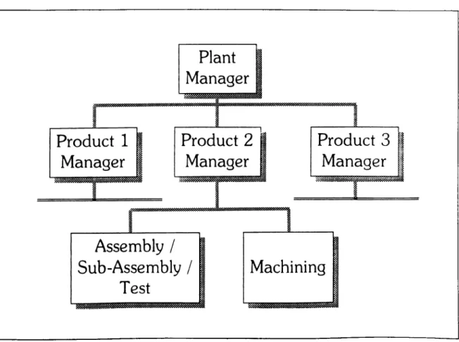
Figure 1 illustrates the focused product organization;
Figure 1. Focused Product Organization
In this example, subassembly facilities unique to the product are combined with the assembly facility. Similarly machining operations that produce product components are physically organized in facilities adjacent to the product assembly. Both assembly and machining are the responsibility of the product manager. Not
all businesses have sufficient volumes to justify machines, cells, and subassembly facilities of product lines. In these cases, the focused organizations of assembly and machining may be separate.
In productivity improvement projects, delegation of authority and responsibility to subplant level, reduction of personnel, and simplification of the process are some of the factors that enable companies to reduce the total number of supervisory personnel and to increase the span of control. [3]
Product versus Process Focus
In his work defining focus, Skinner suggested organization of subplants by product. However, some plants have broad product families and/or costly equipm ent that dictate focus by function. Perhaps most manufacturers need a mix of product and process orientations. Large businesses with broad product lines are most often organized as functional process factories.
Where feasible, subplants organized by product are superior to those organized by process. In a focused-product subplant, the manager can have both the authority and the responsibility for monitoring all aspects of the business, including costs, schedules, and quality performance. Ideally, responsibility by product can also span every manufacturing process, including not only final assembly or finishing operations but also production of all manufactured components. However there are several reasons for organizing component and subassembly production by process rather than by product. The most important is the imbalance in speed and capacity of the final assembly/finishing operations and in subassembly and component production. Often focus by process and product is appropriate. Subplants can and should be organized around the location and the structure of the existing departments. The advantage of such an approach is realizing many benefits of the focus with minimal reorganization cost.
Materials Management
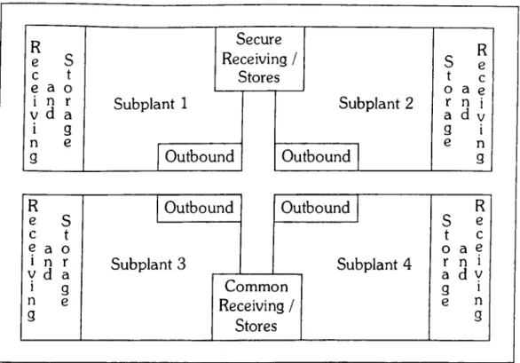
The complexity of materials management function increases with the factory size. Therefore, focused factory organization provides a basis for returning to the simple, low-cost methods and procedures of materials management in the small factory. Figure 2 shows such a setup;
R e S c t e a o i n r V d a i g n e g Secure Receiving / Stores Subplant 1 Outbound Subplant 2 Outbound R e c a e d V i n g R Outbound Outbound R e S S e c t t c e a o o a e i n r V d a Subplant 3 Subplant 4 a d Vr n i 1 g Common g > n e Q Receiving / e n0 3 Stores 3
Figure 2. Focused Storage
The material management setup in figure 2 is very effective and simple but far from ideal. There are two main reasons:
1. Unlike Japan for many western manufacturer theft parts are a big problem and a significant cost center. Therefore, in this example a secure receiving and storage room is included.
2. The materials management includes vendors as an important factor. Shipment and delivery contracts are very important in designing the focused storage layout. For many factories it would be difficult to negotiate with
vendors and transporters delivering the same parts and materials used to different receiving docks. However, in Japan many manufacturers have agreements with their vendors. Thus vendors respond to different requirements, such as delivery to various docks in the factory, or special packaged or manufactured parts for use of the manufacturer in such a setup. In the example above, this constraint causes to design a common receiving/store room.
Traditional factory organization includes the material management function as a separate and specialized division. Figure 3 shows such a traditional materials m anagem ent organization:
One of the disadvantages of such an organization is that the responsibility for total performance is split between plant operations and materials management. None of the organizations can individually control operating results.
In productivity projects the goal is to establish the focused materials m anagement setup. However, less dynamic progress implies reorganizing staff functions and integrating them into the subplant. The focused organization cannot totally eliminate the materials management function. Although transfer of the receiving, storage and work-in-process inventory to the subplants is possible, issues relating finished goods warehouse is still materials management’s responsibility. The reason behind this is the need of mixing the end products for customer shipments. For most companies, finished goods storage- and traffic and shipping functions- will remain in the materials management organization. [3]
Kitting is not only inherently costly, but also increases manufacturing lead time and total inventory requirements. Because kitting is like the process of assembly, time must be scheduled for both performing the operation and for completed kits to sit in queue awaiting assembly. To reduce kitting cost the perm anent kit technique is very useful. This technique achieves the decoupling of assembly lot and kitting lot sizes, as well as minimization of kitting costs.
10
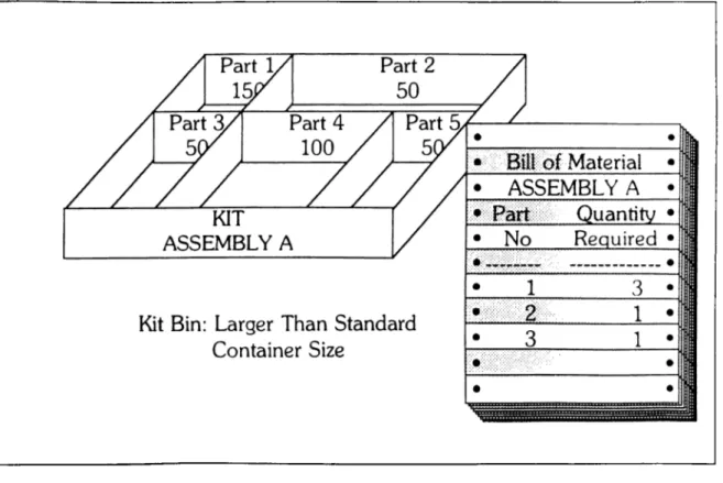
Figure 5. Permanent Kit
The kit can have one or more permanent trays/boxes contain spaces for each part num ber listed in the bill of material. The example illustrated in the figure 5, the target kit size for assembly A is 50 units. Since part one is used three times on assembly A, the target kit quantity for part one is 150 units. Similarly other part quantities are multiples of assemblies, according to their usage in the assembly. Also the compartments in the kit should be somewhat larger than the size of the
component containers. This permits the storekeeper to put a full container into the compartment when the quantity within it is low. It also may allow him to place the container directly into the kit compartment to avoid the time and cost of transferring parts. In the kit, the compartments are of different sizes to match the size and required quantities of each component. [3]
To sum up, small, focused stores, at the point of use for purchased items and at the point of supply for manufactured ones, are the ultimate in storage technology for these types of items. There will always be a need, however, for larger storage facilities for certain types of items, such as finished products and service parts. The best in modern storage technology matches containers to demand, part size and weight, and racking systems. Efficient receiving, stocking, and issue procedures and facilities have the potential to bring about major reductions in needed cubic space and in the cost of storage labor and equipment.
A ssem bly P rocess D esign
The improvements in the assembly area are higher than any other area of the factory because of the high capital investment. The symptoms that the productivity project teams face often are; [3]
11
1. The area occupied by the existing assembly line is more than necessary. Excess space around the process fills with the unnecessary inventory, that causes wasted time and motion, requires greater plant and equipment investment, and inhibits team spirit.
2. The sizes of containers used at the assembly line require the area to be larger than necessary. Big containers also increase the time and motion involved in taking something from (or putting something into) a container.
3. Employees’ capacity is underutilized in terms of quality and quantity. Physical process design inhibits teamwork and team spirit since the distance between workers is too great.
4. In numerous cases, tools, fixtures, and low-cost automation are not used to improve assembly jobs in terms of the time required for the operation, the quality of assembly and worker comfort.
5. Com ponent shortages frequently interfere with producing a schedule.
6. A bureaucracy of support organizations adds time and cost to the assembly process.
Number of Lines
At the start of the project the main issues to consider are whether the present num ber of assembly lines is right, and if there should be fewer or more lines. To make such a decision the project team should consider the following facts: [3]
12
1. Fewer lines to produce the same number of products will permit short cycle time. This is usually accompanied by productivity gains through simplified, shorter, individual assembly operations and the subsequent reduction of wasted time and motion in the shorter operations. Conversely, splitting one line into two will lengthen the cycle time for each product; and this is likely to reduce productivity.
2. If two products or product families produced on two different assembly lines have a high percentage of common components, combining them into one might not cause the number of containers on the combined line to be significantly more than on either or both of the lines. If there is a little commonalty this will increase the number of containers on the combined
line. This will increase both the size of the line, and the time and motion required. Another effect of combining this type of lines will be the need for removing and bringing of the containers as the product or product family changes. This will increase the material handling costs.
3. When the sizes of the two product families are different than combining lines will be add capital costs relating the fixtures, tools and transport equipments.
4. Combining two lines will be lower the space used. However, the space will be greater than the expected because of the different type of tools and fixtures, as well as the components.
5. The simplicity of the design is the primary goal of a productivity project. Combining two lines producing different families will make the design more complex.
As a conclusion determining the number of lines is not a straight decision. If there is a possible opportunity in changing the number of lines after the first evaluation of lines, further analysis is necessary. However, team should keep in mind that such an analysis will double the design efforts. [3]
Assembly Line Shape
In most of the factories the shape of the assembly line is straight. However the straight line is the least desirable one. The serpentine shaped assembly layout is more feasible from the productivity standpoint. Figure 6 shows such an assembly layout with storage areas:
14
The benefits of serpentine shaped assembly lines are:
1. The distance and the cost of returning pallets are often substantially less. Conversely in a straight line on which pallets or carriers exist, it is necessary to build conveyors for the pallets or the carriers to return them to the start of the line.
2. The major advantage of the serpentine shape is cultural rather than tangible, like reduced motion. The serpentine assembly layout brings all employees on it into reasonably close proximity. This physical nearness creates a bond that promotes teamwork.
3. The long straight line results that people on both ends do have inferior communication. Usually the people at the end of the line are inspectors. As an inspector identifies a defect, it takes a long time communicate with others and identify the reasons. This causes losses. With the serpentine shape if one defect is identified, it is easy to stop the line because of the physical closeness and fixing the problem. Quality defects often drop by 75 percent or more, simply as a result of converting assembly to a serpentine form.
4. The management and supervision of serpentine shape are easier. Long straight assembly line requires more than one supervisor. Therefore the responsibility is divided. However, serpentine shape makes the supervision easier because of the physical proximity.
5. It is easier to develop and change a layout in which all process blocks are compact rectangles. People who have worked on plant layouts can readily understand the difficulty of designing the optimal flow, when everything else must be arranged around straight, long lines that occupy narrow and long strips of the factory.
6. The serpentine form is better for the ratio of major aisle space to process space. The straight line often has major aisles on each side for its entire length. By contrast, the serpentine shape usually has aisles on two or three sides of its perimeter.
16
7. With automated transport, the straight line is frequently so long that existing buildings are not big enough to hold them. In that case the internal walls dictated where the corners placed in the line. The serpentine shape therefore is not inferior considering corners.
8. Finally not all products require a long final assembly line. Many manufacturing plants assemble small products with relatively few components. These factories have assembly operations with fewer workers and workstations. In that case of a one- or two-man assembly facility, the shape of the line should almost certainly be straight. For a line with two to eight assembly positions, a straight, L-shaped or U-form is likely to be applicable. Lines with nine or more positions make it feasible to consider serpentine shape. As a practical minimum, the serpentine and U-form assembly facilities tend to have five positions for each line length.
Not all lines are simple serpentine or U-shaped since complex products change size and shape in the process of assembly. One project team can design a line of roughly U-shape but with different paths of travel for various products. [3]
In-Line and Parallel Sub assem b ly
The vision about the subassemblies is to avoid independent subassemblies. The recommended model is a network of subassemblies that are closely coupled with the main assembly.
17
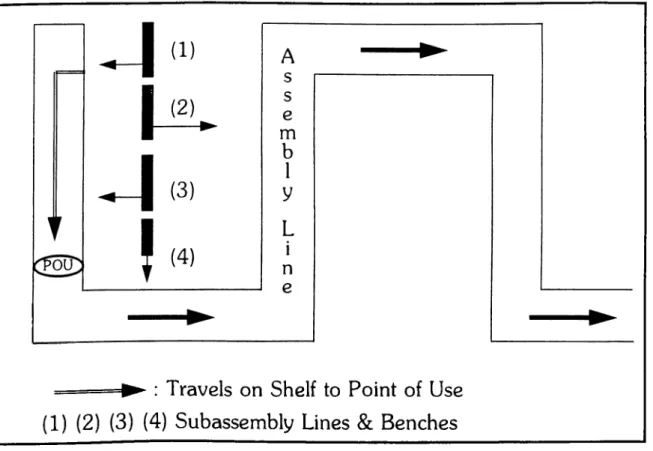
► : Travels on Shelf to Point of Use (1) (2) (3) (4) Subassembly Lines & Benches
Figure 7. Parallel Subassembly
In figure 7 the main assembly and four subassemblies that are coupled with the main assembly. Designing the subassembly processes to be perpendicular to the final assembly is often a bad practice. A better practice is producing in the main line or on a parallel line. In figure 7 four subassemblies are manufacturing on a line between and parallel to, two legs of the main assembly line. If two subassemblies are necessary at the same point of use (POU) in the main
assembly line then one of them should be carried to there either on a conveyor or with the main product on the main assembly line.
The parallel or in-line subassemblies help Just-in-Time and limiting the subassembly inventory level. [5]
18
Assembly Line Length
Longer than necessary assembly lines penalize the profitability of the companies. They are costlier in the following ways;
1. Excessive space on the line permits the line to hold more work-in-process units than just the units being worked on. This increases the inventory investment and the time required to assemble each unit.
2. The investment in plant and equipment is larger than necessary. 3. Supervision is costlier since the are is larger.
4. Liberal use of space on and around the line causes workers to walk and reach more, cutting the amount of time they can spend on assembly.
The amount of buffer stocks on the line effects the line length. Buffers cause, on the other hand, make the space occupied larger and cooperative recovery difficult. For the longer cycle times the cooperative recovery is more likely to apply, conversely for the shorter cycle times the buffer stocks are more common. The idea without buffer stocks the speed of the line equals to the speed of the slowest person in the line is not completely true. In the case of buffers in use the slowest person has his inbound buffer full and his outbound buffer is empty. [3]
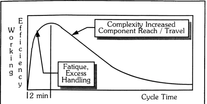
Cycle time is the most important factor in designing of an assembly line because it is a variable of the physical layout. The volume of production is the determining factor of cycle time. The targeted volume of production determines the cycle time. As an example, consider a target production volume of 225 units per shift. Assuming that the productive time in each shift is 450 minutes than the cycle time is 2 minutes.
However cycle time has a great effect on productivity. Cycle/efficiency curve is illustrating this effect; [3]
19 w 0 r k 1 n g
Figure 8. Cycle/Efficiency Curve
For short cycle times less than 2 minutes, efficiency is low because the workers should perform short and repetitive tasks. Cycle time for longer than two minutes the reason of diminishing efficiency is the increasing complexity of work and component reach and travel.
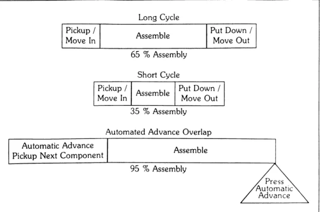
Figure 8 shows the comparison of nonproductive time spent in long and short cycles:
20
Figure 9. Handling Time Tradeoff
Automating the movements and pickup/put-down processes can solve the problem of decreasing productivity percentages. [3]
One-Touch Changeover
Although there are an unlimited number of techniques that contribute to superior productivity, a few of these warrant special attention: organizing small, focused subplants; improving space utilization; and reducing the time, cost, and complexity of setup or changeover. Of the three, setup reduction is the easiest, lowest-cost, and fastest type of improvement that most manufacturers can make. Reduction of setup costs is important for three reasons;[3]
1. Production lot sizes are large when changeover cost is high; thus, inventory investment is high.
2. Fast, simpler changeover techniques eliminate the potential for the mistakes in setting tools and fixtures. Thus, new changeover methods substantially reduce defects, while eliminating the need for inspection.
3. Fast changeover techniques can be used to make additional machine capacity available, that can delay purchasing new machines to gain additional capacity.
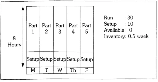
A simplified production schedule for a plastic injection press requiring a 2- hours setup is illustrated in figure 10.
21
8
Hours
Part Part Part Part Part
1 2 3 4 5
Setup Setup Setup Setup Setup
M T W Th F Run Setup Available 30
10
0
Inventory: 0.5 weekFigure 10. 120 Minute Setup
The machine is used to produce, each week, part numbers 1 through 5. The setup of each part requires 2 hours, the production of each six hours. In the five- day week the machine runs 30 hours and setup requires 10.
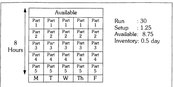
When setup of the machine is reduced to three minutes, as shown in figure 11, it becomes practical to run every part each day, that gives a great flexibility to the production operations.
22
8
Hours
Available
Part Part Part Part Part
1 1 1 1 1
Part Part Part Part Part
2 2 2 2 2
Part Part Part Part Part
3 3 3 3 3
Part Part Part Part Part
4 4 4 4 4
Part Part Part Part Part
5 5 5 5 5 M T w Th F Run : 30 Setup : 1.25 Available: 8.7 5 Inventory: 0.5 day
Figure 11. 3 Minute Setup
Shigeo Shingo, one of Jap an ’s pioneers in setup reduction, has written on of the most comprehensive and detailed books^ on the subject of setup reduction. [20]
The Step-By-Step Approach
The productivity issues, the essence of reengineering, superior manufacturing techniques and tools are issues that are known by many people working in the manufacturing companies. However, application of some of these issues without having a complete vision, the full benefits cannot be achieved. For such
^ Singeu Shingo, A Revolution in Manufacturing: The SMED System (Cambridge, Mass..: Productivity Press, 1987).
productivity works remain many opportunities for further improvements. The aggregated costs of this type of projects, performed with little effort for training, is much more than an integrated project, whose scope covers the whole area. In order to achieve the full benefits of the superior manufacturing techniques, the companies often do not have the required experience, people and sources. The most important inability of firms is methodology. Here, the needed help is provided by consultants. Consultants provide a fresh and objective perspective. Often times consultants will be able to provide examples of how similar projects were conducted in other companies and industries. They may also arrange visits with companies identified as being among the best in performing a specific process.
Determination Of Starting Point
The areas often available for improvement projects are:
1. Final assembly (or packaging) process for a product or product family
2. A selected subassembly process for one of the types of major subassemblies used on the product or product family selected
3. Selected types of manufactured components used on the final product/product family and/or major subassembly
4. Purchased, manufactured, and finished goods storage
5. Selected machines on which to perform setup and maintenance improvement projects, usually corresponding to the areas selected for a type of manufactured component.
23
In order to select one or more of these areas, the consultants firsts determine the answers of a few key questions. These questions are:
24
1. Which final products or product lines have the highest value of production? 2. Which types of machines and fabricated components have the highest value
of production?
3. Which types of purchased items have the highest usage value?
The answers to these questions point the area for a start. The objective, though, is achieving the highest magnitude of improvements with minimum project cost. Therefore, a conclusion that profit and fastest payback are the motives for projects is very appropriate.
The important issue in the selection of area or areas is balancing the tradeoff between the limited funds for the projects and ensuring the best possible degree of successful integration.
The side considerations are:
1. Manager and supervisor enthusiasm for participating in the project. Ultimately, the degree of success and the difficulty of achieving goals will depend on the support (or resistance) of these key individuals.
2. Management priorities, which may be based on quality and delivery problems or new product plans.
3. The am ount of effort required to design and implement improvements
4. Existing plans for automation/reorganization of areas.
5. The size of the machines and equipment that would have to be moved and, therefore, the cost to move them. [3]
Groups of employees who meet a few minuets per week cannot produce the same magnitude of benefits that highly trained, experienced, full-time teams can. Nevertheless, there is no reason to exclude employee groups in an improvement program, nor should a full-time project team serve as a substitute for managem ent and employee participation. People that have experience in reengineering projects, and people that have experience in the ongoing process can generate best solutions to problems by working together.
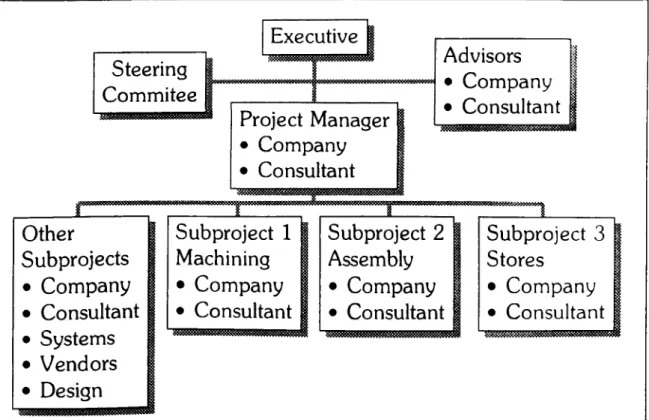
The recommended organization chart of project team is in figure 12:
25 Steering Commitee Other Subprojects • Company • Consultant • Systems • Vendors • Design Project Manager • Company • Consultant Advisors • Company • Consultant
Subproject 1 Subproject 2 Subproject 3 1
Machining Assembly Stores 1
• Company • Company • Company |
• Consultant • Consultant • Consultant I
26
It is important to consider the help of a qualified consultant to;
1. Avoid reinventing the wheel, in terms of dealing with problems that have already been solved or devising solutions inferior to those previously invented in other companies
2. Obtain experience and methodology for conducting improvement projects 3. Provide the necessary manpower to accomplish as much as possible, as
soon as possible. Often, a company does not have enough personnel to completely staff a project and prefers to use a consultant as temporary manpower, not on the permanent payroll after improvements have been implemented.
4. Bring fresh perspective to the project team.
5. Gain easier access to executive management than internal project teams. Executive management understands that the most cost-effective way to benefit from the use of a consultant is to maintain frequent and substantive contact. The consultant often helps company personnel win approval for improvements that management has not previously taken the time to properly understand and evaluate. 13]
Project P hases
The project scope changes from project to project. However, it is possible to classify projects as three types: improved operations, design, and implementations; short-term improvements (e.g., setup reduction); and plantwide master plans. Projects to improve operations are usually performed in three phases: (1) planning and initial design, (2) design, and (3) implementation.
Phase one objective is to perform minimal design work in the areas to be able to prove that improvements can be made and determine the specific changes that would be required. This would encompass designing new processes for a small, but representative, part of each area. The initial phase helps quantify approximately the potential costs and financial benefits of the project, and finalize a project scope and work plan for designing improvements for the total area. At the end of phase 1, there is a checkpoint that allows management the opportunity to change project plans, and also enables it to better understand the specific types of change applicable to the area. One small area was selected in that phase for pilot to represent the benefits can be achieved. After first phase the design scope enlarged to the selected area and phase three (implementation) enables to enjoy all the benefits of the project.
Phase 3 (Implementation) includes the physical arrangement of machinery according to the new layout. The new production procedures are applied in this phase.
Finally, in order to be successful in the productivity projects the following points should be considered. These are keys to success:
Top m anagem ent commitment, communications, quick action, full-time, focused team, experience, and methodology. [6]
CHAPTER 3
CASE APPLICATION: ANALYSIS OF A TURKISH ELECTRONIC HOME APPLIANCES MANUFACTURING PLANT USING PROVEN
METHODOLOGY
Introduction
Chapter 2 explains the reengineering concepts in the manufacturing environment, and a step-by-step approach is recommended for the manufacturing productivity projects. According to this approach, first phase of the project includes the analysis of the plant under the light of the methodology and a pilot installation to show the magnitude of the benefits in order to form a basis for the decision to continue with the second design phase. Before the first phase starts, consultants analyze the plant, and a pilot area is chosen for phase I. The project proposal should include the analysis and targeted benefit magnitudes for the senior m anagem ent decision. This chapter explains how the methods and principles can be applied to a company that have an electronic home appliances manufacturer’s plant in Avcılar, Istanbul. [23]
The company mainly produces TV sets for both domestic and international markets. The daily production rate is one thousand TV sets. Other products are stereos and this product family includes three different models. The models in TV sets are numerous according to the screen size. However, if the processes and the electronic circuits are considered, there are really two different models. One of the models is being produced under the license of a German manufacturer, and the
other modei's design was done by the company with modifications of German design.
The Avcılar Plant includes the whole process of TV production. The frame of the TV, the tube, electronic components, wires and packaging materials are raw materials used in production. The electronic components are supplied by imports. The frame of TV sets are produced by the joint venture of the company with another firm. The plant is divided into five main divisions according to the processes. The raw materials and finished goods warehouses are excluded from that number.
After several plant tours, and meetings with both the top executives of the company and the Avcılar Plant management, analysis of the plant was conducted by the author. This chapter includes the current process of TV set manufacturing, the analysis of the process according the methodology, and the observations and the results of that analysis with the proposed benefit magnitudes.
Current P rocess and O bservations
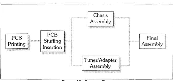
A TV set is composed of mainly two printed circuit boards (PCB) namely tuner/adapter and chassis. Some supplementary parts are also included for different features such as teletext or remote control sensing. Therefore, the process flow begins from PCB printing and ends at the final assembly. Figure 13 illustrates the main process flow;
30 Chasis Assembly PCB Printing PCB Stuffing Insertion Final Assembly T uner/A dapter Assembly
Figure 13. Process Flow
The observations about the main parts of that process are as follows: 1. PCB Printing:
PCB printing department in the plant has a traditional organization
structure. The department was supervised by a department head and two supervisors manage the two different parts in the process namely cutting and chemical process. The pattern of PCB are first exposed on copper coated plastic sheets. These sheets are put into hydrochloric acid and the copper coating outside the patterns is removed. PCB’s are cut into pieces and then the holes are drilled. The copper pattern is protected by spaying a film.
Department is located in a small room. In the PCB printing area 2 acid tanks are placed. The cutting machine and drills are put near the tanks. Therefore the time and motion done during the process are not excessive.
In this area the work in process inventory level is high. The finished PCB’s are adequate for the five days’ production. The main reason of high WIP is the process nature. The acid tanks are filled with at least 20 sheets. After cutting the sheets there are numerous PCB’s waiting to be drilled. The imbalance of chemical and drilling process increase the WIP inventory.
Another related issue is the low level of automation. Almost all tasks are performed manually. This causes the incapability of printing two sided PCB’s which require the coating of holes. Two sided PCB’s are supplied by vendors.
PCB printing process is an easy one. Therefore, it includes minimum non value added activities. Automation can be introduced in this area for being more productive. However, further analysis is required to determine the degree of automation.
2. PCB Stuffing/Insertion:
In this area, a traditional organization structure is observed. There is one department head responsible from the operations, and two operators run the machines. The equipments are complicated, and use of advanced technologies make the job very accurate for good quality and easy for process. High level of automation makes the redesign of process difficult. However, this department is the area where heavy use of electronic
components makes it possible to implement focused storage techniques and apply focused materials management concepts.
3. Tuner/Adapter Assembl]^:
Tuner/Adapter assembly line has the traditional straight shape. In this area small parts are used for the assembly of the tuner or adapter. This fact makes material handling and storage simple. The line length is short. There are a few raw materials stored in this area. The assembly line was designed by German engineers.
Management observes the throughput time of this assembly line very closely and special emphasis is put to shorten this time. Total throughput time in tuner/adapter assembly is 18 minutes. Management works to decrease this time to 16 minutes which is the standard throughput time for this assembly
32
line in German factory. However, cycle times in the workstations are very short resulting high numbers of workstations and buffers between them. By lengthening the cycle times for the workstations would lower the number of workstations and therefore the length of the assembly line can decrease. 4. Chassis Assembl]^: The chassis assembly layout is in the traditional linear
shape. One positive observation is the low level of the WIP on the bench. The drawbacks in this are is the invisible use of finished goods and unstructured rework. The produced chassis do not labeled. Therefore, it is impossible to determine when the chassis is produced. This makes the cause and effect relationship unclear. As a result, the quality problems are common on each workstation, which cannot be detected at the inspection point at the end of the line. This quality invisibility causes a massive am ount of rework activity. Rework processing is complex. If a problem is detected in the final adjustment of the circuit, the part is put into a wheeling cart for rework. The workers making adjustments are also responsible from rework. If they have time between adjustment tasks they take the circuits from wheeling cart and work n them. However, after the problem is determined they fill a log for the causes which is inadequate because of the uncertainty in the production sequence. The assembly line is also very lengthy causing long travel distances.
5. Final Assennblv:
The final assembly area is the place where large parts and components are used. The observations reflect a good opportunity for productivity
improvements. The final assembly process is not closely coupled to chassis assembly. Therefore the chassis subassembly inventory level is high. The inventory level of chassis is four days of production. In this final assembly area significant non-value added activities are detected. The quality
inspection process checks only the product not the process. Therefore, fixing the problem caused by quality defects is very difficult. The product flow within the final assembly is very complex. The storage facilities of materials used are far from the point of use (POU). This causes long traveling
distances and wasted time and motion of material handlers. Inefficient use of the finished goods storage area limits the output rate by the excessive finished goods inventory on the final assembly area. The finished goods warehouse is insufficient for the production rate. The line supervisors do not observe the sequence of flow. Therefore, although a lot of reworks are done, the process is not effected from the detected problems. This causes significant quality problems. Besides, the WIP inventory is very high in this area. There are 200 TV sets on the carts.
Project S co p e
According the above analysis of the plant, the final assembly area is the most appropriate part for a pilot project. (Phase 1) The reason for such a selection is the magnitude of the benefits can be achieved by the pilot. The final assembly area occupies the biggest space in the plant. Besides, the finished goods storage facility is not enough. The saving in the space is therefore can be used as finished goods warehouse.
The throughput time in the final assembly process is larger than the throughput times in the other processes in figure 13.2 Therefore the reduction in the throughput time will result the lead time will drop significantly.
33
^Throughput time in the final assembly is four hours, including the testing of the TV which is two hours.
The reason of the quality defects often is the final assembly process. For example, the quality inspectors in the finished goods reject one daily batch in every two week. In that case, packages of that day’s production are opened, every TV set is controlled and then repackaged. The defective items are sent back to the production for rework. This volume of quality defects is therefore one tenth of the production, which is very high. If the process of final assembly redesigned, that would help to decrease the quality defects. As a result, a big amount of savings is possible to achieve.
The senior management of the company stated that the financial inability for capital investment is the biggest problem of the company. Therefore it is very important to decrease the WIP inventory level in the final assembly area whose worth is very significant for improving the company’s financial situation.
One other reason of the selection of final assembly as the pilot is the opportunity to decrease labor force working in that area. These workers can be shifted to the other areas of the plant. This will increase the efficiency of the labor force use.
As a summary, the project scope covers the application of the operation improvement techniques in the final assembly area. The reason is that the magnitudes of the benefits are larger here than the other departments. Such a pilot, therefore, can best illustrate the significance of the reeengineering project.
Final A ssem bly P rocess R edesign
The recommendations for the final assembly area redesign are as follows: 1. Focus only on the final assembly area for a pilot productivity project.
2. The scope of the improvements could include all major TV models flowing through the final assembly production line.
3. The final assembly process should be closely coupled with the chassis assembly in order to eliminate the non-value added operation in between. 4. The sequence of the products through the chassis production and final
assembly areas should be rigidly maintained. This would greatly improve quality cause and effect visibility and provide a basis for developing process as well as product quality standards.
5. The throughput time including the chassis assembly should be dramatically shortened. Quantifying and improving the proportion of value added time to total throughput time and value added activities to all final assembly activities are very important. As a result by the shortened throughput time, the manufacturing of the product would be more flexible to meet actual demand.
6. The final inspections of manufactured goods do not add value to the customer or manufacturing process. It has only negative effects on the cost and the lead time of manufacturing process. Therefore, during the above activities quality control should be done at any step and aimed to improve the quality of the process. This would increase the quality of the final product and customer satisfaction.
R esults
As remembered from the step-by-step approach, the next step of the analysis is setting targets for the benefits by the management. Table 1 summarizes the targeted percentages of improvements in the final assembly area of Avcılar plant;
36
The numbers in the electronic industry column are taken from the improvements Production Factors Electronics Industry Company Targets
Lead Time 20-85 % 40-60 %
Setup Reduction 88 % N/A
Quality 60 % 30-50 %
WIP Inventory 75-92 % 50-65 %
Direct Labor 10-50 % 20-30 %
Indirect Labor 20-60 % 20-40 %
Space 30-50 % 25-40 %
Purchased Goods 5-15 % N/A
Payback (Months) 9-12
achieved in the projects performed worldwide. The differences between the numbers targeted for the company and the industry averages source from the limited scope of the pilot project and the conditions specific to the company. The targeted benefits were discussed with the company’s executives and accepted as meaningful numbers as the recommendations in the previous section are considered.
Table 1. Targeted Final Assembly Benefits
As a result of the analysis, a proposed project organization and work plan has been prepared with a team including three experienced consultants and three people from the factory who are experienced in the final assembly process.^
The planned deliverables of the project at the end of Phase I would be:
1. The recommended changes would take the form of "Conceptual Designs". Since the recommendations developed during such projects are often in opposition to the more traditional objectives of automation-dependent,
department-focused designs, it is critical that the conceptual designs produced during the review clearly illustrate the underlying principles and operating techniques explained in chapter 2 of the thesis.
2. Sketches of recommended changes to production process. These are vital to understanding the most important aspects of the new process areas and potential benefits.
3. Development of sketches and "Conceptual Designs" of new manufacturing "cells", production techniques, and line interfaces.
4. Order-of-magnitude estimates of the improvement in material flow distances which would result from recommended design changes.
5. Plant layout ideals and standards.
37
6. A high-level costAienefit analysis would be developed for the final assembly area reviewed. This would also help to the management to decide to go on with the implementation.
C onclusion
In this case, one manufacturing plant was reviewed under the reengineering considerations explained in chapter 2. The methodology and the step-by-step approach help organizing the project organization and work plan. The analysis of the plant gives the area to implement a pilot project. Analysis of that pilot area gives the targeted improvement percentages. A detailed cost/benefit analysis forms a basis for the management decision to continue with the following phases. The considerations explained in this chapter illustrate how we can apply the concept to the manufacturing plants individually.
CHAPTER 4
APPLICABILITY OF REENGINEERING IN TURKEY
Introduction
Chapter 2 of the thesis explains the reengineering concept, the application of this concept to manufacturing companies considering different processes in a plant. Besides that, step-by-step methodology is given that shows how we can apply the "simplify, automate, integrate" principles to manufacturing productivity projects. The recommended project scope analysis and phased approach are applied a few thousand times worldwide. The results of these applications are summarized in Appendix B. Chapter 3 gives an example how such a project is organized and how the analysis of a plant performed. The analysis results and relating recommendations are also given on a high level basis.
With the whole information, this chapter analyzes the situation in Turkey and answers the question of applicability of these concepts. Chapter includes the current manufacturing processes and potentials in Turkey, the difficulties that project teams would face and remedies of these problems.
Turkish Manufacturing C om panies
Turkey has a lot of manufacturing activities. There are many companies spread mainly in the western part of Turkey because of the advantages of better infrastructure in these regions. Government owns many companies to promote industrialization. Although, government owned companies are discussed very
widely by the community, many of them are giants with extremely high production volumes in key industries. Besides government owned companies, private sector has hundreds and hundreds of production facilities in the country. The developments of industries are supported by the economic and strategic plans of the governments. As a developing country Turkey has high growth rates in last decades that turns the community from agricultural production to the industrial production. The reflection of this fact can be observed in export bundle of Turkey. From year to year the percentage of industrial goods in Turkish export volume increases with the increasing volume itself.
Although the country has a big size of industry, the research and development activities are minor. This fact causes firms import technology from abroad. Therefore the processes in manufacturing facilities are effected by the foreign designs. However, because of the lack of required resources for investing new developed technologies, the processes even can’t change with the changes in the processes worldwide. Therefore the processes in manufacturing facilities are often moderately old and can’t benefit from the last developments.
The human resources are limited in Turkey because of the low level of education. It is difficult to find experienced and well-educated people. Because of the high birth rate the investments to education are not enough to have the required human resources, especially for skilled blue collar creation.
Because of the inefficient and outdated processes the competitive strengths of manufacturing companies in international markets are low, except a few industries whose raw material is produced in big volumes such as some agricultural industries. One example of low competitive force is automotive industry. In recent days the so called "automotive lobby" puts the pressure on government to
maintain the trade barriers in automobile imports, although integration to European Community requires the reverse action.
Because of the outdated processes and need for gaining competitive force, Turkey has great potential for reengineering and manufacturing productivity improvements.
Advantaged and D isadvantages of Manufacturing Productivity Projects in Turkey
Although there is a great potential for reengineering projects in manufacturing companies, a lot of difficulties wait project teams.
One difficulty is the recent high inflation rates in Turkey. Most manufacturing productivity projects aim to decrease the WIP and finished goods inventory in order to save stock holding costs and space occupied by the goods, parts, and components. However, in the inflationary environment the management of many companies consider the inventory as money making capital investment, because the monetary worth of the items increases sharply during the process. Investing money in goods and components has a good rate of return because of the high inflation.
Another difficulty sources from the legal environment. Many industries are protected by the high trade barriers for import. This makes companies can sell their goods easily to the domestic market, because the equivalent important goods’ prices are very high because of the tax and funds applied during import. However, this situation will change in a few years with the increasing integration to international communities efforts. To be a member of EC, the economic region forming among the Black Sea neighboring countries force the Turkish Government lowering the tariffs, quotes, and other trade barriers.
One other reason diminishes the necessity of gaining competitive strength is the unorganized structure of consumers in Turkey. The consumers’ reactions to low quality goods are weak, because of that unorganized structure. However, the organizations like T.S.E. Turkish Standards Institute or quality forums, and communication companies work to educate consumers about quality issues. Protection of consumer movement begins to increase sharply. This will force companies certainly put more emphasis on quality issues.
One other reason specific to manufacturing companies that make such productivity work harder is the lack of productivity vision. Many company executives try to cutting costs and produce more. However, they have so little knowledge about business reengineering, and the benefits that can be achieved during such projects. The interviews with company executives support that fact, because many executives told that such an idea is entirely new to them. In order to publicize the idea of reengineering the promotional activities of consulting firms, that are experienced in this type of work, would be very useful.
However, in Turkey the number of professional consultants is so little. This is another difficulty of reengineering applications in Turkey. Because as it is explained in chapter 2, the contribution of experienced personnel are essential for manufacturing productivity projects.
One other difficulty is the scarcity of companies’ resources, which makes the resource allocation even harder. The budgets separated for development and applications of new concepts are minimal. The remedy of that problem is the step-by-step approach itself. The reengineering project can be divided into smaller segments and the biggest opportunity offering project can be run first. The