Research Article
The Mechanical Behaviors of Various Dental Implant
Materials under Fatigue
Fatma Bayata
1and Cengiz Yildiz
21Department of Mechanical Engineering, Istanbul Bilgi University, 34060 Istanbul, Turkey
2Department of Mechanical Engineering, Istanbul Technical University, 34469 Istanbul, Turkey
Correspondence should be addressed to Fatma Bayata; [email protected]
Received 15 November 2017; Revised 17 February 2018; Accepted 22 March 2018; Published 22 April 2018 Academic Editor: Vincenzo Guarino
Copyright © 2018 Fatma Bayata and Cengiz Yildiz. This is an open access article distributed under the Creative Commons Attribution License, which permits unrestricted use, distribution, and reproduction in any medium, provided the original work is properly cited. The selection of materials has a considerable role on long-term stability of implants. The materials having high resistance to fatigue are required for dental implant applications since these implants are subjected to cyclic loads during chewing. This study evaluates the performance of different types of materials (AISI 316L stainless steel, alumina and its porous state, CoCr alloys, yttrium-stabilized zirconia (YSZ), zirconia-toughened alumina (ZTA), and cp Ti with the nanotubular TiO2surface) by finite element
analysis (FEA) under real cyclic biting loads and researches the optimum material for implant applications. For the analysis, the implant design generated by our group was utilized. The mechanical behavior and the life of the implant under biting loads were estimated based on the material and surface properties. According to the condition based on ISO 14801, the FEA results showed that the equivalent von Mises stress values were in the range of 226.95 MPa and 239.05 MPa. The penetration analysis was also performed, and the calculated penetration of the models onto the bone structure ranged between 0.0037389 mm and 0.013626 mm. L-605 CoCr alloy-assigned implant model showed the least penetration, while cp Ti with the nanotubular TiO2
surface led to the most one. However, the difference was about 0.01 mm, and it may not be evaluated as a distinct difference. As the final numerical evaluation item, the fatigue life was executed, and the results were achieved in the range of 4 × 10⁵and 1 × 10⁹ cycles. These results indicated that different materials showed good performance for each evaluation component, but considering the overall mechanical performance and the treatment process (implant adsorption) by means of surface properties, cp Ti with the nanotubular TiO2surface material was evaluated as the suitable one, and it may also be implied that it displayed enough
performance in the designed dental implant model.
1. Introduction
The optimal dental implants require the integration of material, mechanical, biologic, and economic factors. Especially, the stability of the implant under cyclic biting loads, the integrity of the implant to the bone tissue, and stress transformation from the implant to the bone tissue are the most important concerns in the success of implantation. In order to make considerable progress in this technology, it is essential to determine the reasons underlying the failure of implants [1–4]. The long-term mechanical reliability of dental implants is one of the most important concerns, so the cyclic life occurs as a failure problem with them. In this type of failure, fracture mechanism time is assumed as the prime factor to be considered since the damage accumulates over time.
When the deformation reaches a critical level, catastrophic failure takes place in dental implants [5]. Thus, the fatigue can be implied as the main problem affecting the cyclic life. Stress concentrations, which are due to the threads relatively in the structure of the implant and a significant degradation of the material surface containing flaws, determine the fa-tigue behavior and the life of the implant material [6]. For this reason, material selection was paid attention as to provide enough fatigue life in this study.
The fixation is a frequently observed problem in dental implants. The integration mechanism of the implant is based on the placement and then the quantity and quality of cortical and trabecular bones, which affect the primary stability and so the fixation of the implant [4]. Herein, the osseointegration, which consists of anchorage of metallic Volume 2018, Article ID 5047319, 10 pages
implants to the related bone, makes the implant-bone teraction site the most important issue. Regarding the in-teraction, the loss of bone density, which is occurred due to the significant reduction of the dimensions of the mandible (i.e., induced by aging) and the massive atrophic changes, becomes the crucial point [2, 7]. The reduction in size and density of the bone impairs the placement of implants [1]. To solve this problem, bone density and the other factors, for example, applied loads, the length and diameter of the implant, its geometry and surface, the bone-implant surface, and the quality and quantity of the surrounding bone are considered and researched for obtaining the optimization.
Bone resorption is another serious complication in the case of integration in dental implant applications. By modifying the surface properties of implants, bone healing may be accelerated and stimulation of bone growth can be provided. For example, the rougher surfaces stimulate dif-ferentiation, growth, and attachment of bone cells and in-crease mineralization [8]. Therefore, the term of roughness hereof becomes important, so certain implants are known as they are manufactured with rough surfaces purposely [9]. In recent years, the surface properties of the implants are searched to develop for increasing the adsorption to the bone structure. Thus, focusing on the porous materials and their comparison becomes one of the basis of this study.
The other main problem can be marked as inconsistency of the implant with the surrounding bone tissue. In the study of Elias et al., it is implied that rigidity inconsistency between the bone and the implant materials causes stress shielding [10]. This problem is remarked as a high difference between the moduli of elasticity of the bone and implant that induces insufficient transfer of stress to the bone due to the high modulus of the implant. To overcome the problem, they pointed that the materials with lower elastic modulus, which provides closer value to the one of the bone tissues, can be utilized, since they have better stress distribution at the implant-bone interface and lead to less bone atrophy. Ad-ditionally, considering the porous materials and adjusting porosity to match the elastic modulus of the human bone may be stated as another technique in the literature for annihilating the problem [11–13].
In order to sort out all these mentioned problems, the implants were investigated in view of the material in this study. Therefore, different types of biomaterials were assigned as a dental material in the implant model developed by our group. As a dental material, AISI 316L stainless steel, alumina and its porous state, CoCr alloys, yttrium-stabilized zirconia (YSZ), zirconia-toughened alumina (ZTA), and cp Ti with the nanotubular TiO2 surface were tested. The stress distribution
over the implant, bone-implant interaction, and the life and the stability of implants were investigated by simulations under real cyclic biting loads. The effects of materials on the performance of implants were also discussed, and the optimum material properties for dental implants under fatigue were determined.
2. Materials and Methods
2.1. CAD Model Preparation of the Implant and Abutment. First,
a reference implant-abutment model was needed to set an
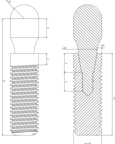
FEA model, so considering the criterions, a design of the implant that was generated by SolidWorks 2012 (Dassault Syst`emes, France) was used in this work. This developed implant model has a 2.0 mm height of the nonthreaded cylindrical neck and an 11.0 mm height of the threaded part. Its diameter is 4.5 mm and length is 13.0 mm. An implant model (AdVent) of a trademark that is Zimmer Dental, Inc. (CA, USA) was used as a base for the thread detail [14]. In Figure 1, technical drawing of the implant-abutment system is shown.
2.2. FEA Model Preparation of the Implant and Abutment. To
assess the effect of different dental implant materials, the CAD data were prepared for the FEA, in which the condition was set according to the ISO 14801. The generated implant, the abutment, and also the implant holder were assembled in CAD software and then exported to the software ANSYS Workbench 16.2 (ANSYS, Inc., USA).
Mesh configuration was set by the method of “tetra-hedrons” to generate 10-node tetrahedral elements. Body sizing option was used for whole bodies to generate finer meshes with the option of “sphere of influence.” The center of sphere was located at the critical region that is near to the second thread from the head of the implant, and the element size was taken as 0.6 mm.
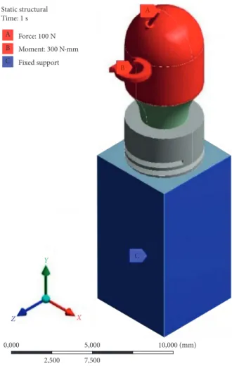
Using the study of Ferreira et al., the frictional connection was defined with frictional contacts, in which the coefficient was taken as 0.3 [15]. The “Augmented Lagrange” option of contact solution formulation was set, and the “Adjust to Touch” option was also imposed for the interface treatment because of the assembled structure bodies that were in touch with each other. The lateral surface nodes of the implant holder were fix supported for the boundary condition. In the literature, it was revealed that a 100 N load is in the range of normal bite forces. Therefore, in this study, 100 N was applied to the top surface of the abutment with an inclination of 30°according
to the ISO 14801 standard [16, 17]. According to recom-mendation of the implant manufacturer, the tightening torque of 30 N·cm was applied to the abutment for dem-onstrating as possible as the real condition [14]. Figure 2 shows the brief FEA conditions.
2.3. Material Selection and Assignment to the Bodies of the Model. For the FE (finite element) solution of the model, the
material properties had to be assigned to all of the bodies in the FE model properly, so the conventional and novel biomaterials were researched in detail according to the criteria as mentioned in Introduction of this study for the ability of being used in dental application. It is known that Ti alloys, AISI 316L stainless steel, CoCr alloys, alumina, zirconia-toughened alumina (ZTA), and yttrium-stabilized zirconia (YSZ) are still studied and asserted as the alternative materials for dental implantation [18–21].
Herein, it would be better to make an elaboration on them and general comparisons between the applicable materials for supporting the reasons of the selection of them. When the literature is searched, it can be observed that AISI 316L stainless steel is preferred and used in dental im-plant applications among the mentioned materials because of
its relatively low cost, corrosion resistance, and ease of manufacturing [18]. Moreover, additional coating is also preferred for decreasing the ion accumulation in the interacted bone region due to the compound elements in the alloy.
The other alloy type is CoCr that can also be used for dental implant applications, and they are regarded as ex-cellent in the corrosion resistance since they have adherent layer of chrome-based oxides on the surface and it leads to a passivating effect. Thus, the implant surface is less rough due to both before and after saliva exposure. The situation indicates that the active material degradation process is less than the other commercial alloys such as titanium [19]. However, manufacturing of this material may be a little bit difficult and take long time relatively, so its usage is limited. On the other hand, usage of ceramic materials can also be asserted as rising up. The ceramic implants become popular and familiar with the patients and clinicians due to their significant wear resistance and superior biocompatibility relatively. One of the popular ceramic material structures is porous alumina that is known as biocompatible in the porous
form and it permits tissue ingrowth that provides an im-portant property of implant stabilization [21]. For that reason, the possible novel ceramic materials like porous alumina were investigated for availability of being used as dental implants in this study. In this context, yttria-stabilized tetragonal zirconia (YSZ) was also studied. It is known as another preferred one in dental implant applications due to its superior flexural strength that is in the interval of 800 and 1000 MPa, toughness, corrosion, and wear resistance [22, 23].
Moreover, the alumina material can also be strengthened and toughened by zirconia. Tetragonal-phase zirconia ad-dition to alumina leads to higher strength and fracture toughness with little reduction in hardness and elastic modulus relatively [24, 25]. Kurtz et al. also imply that higher fracture toughness allows for the manufacture of thinner liners to reduce the risk of impingement and dis-location and improve the stability of the implants [25].
Besides these ceramic materials, when the literature is investigated, a common base material of Ti appears as either a metallic alloy or a ceramic structure that is derived by
3 13 Ø4.50 Ø3 10° 3 2 4 21 R2.25
controlled oxidation. Metallic alloy states of Ti are known as already used in dental implants. They provide superior fa-tigue life and strength. However, they may have a possible toxic effect resulting from released vanadium and alumi-num, so their commercially pure grades are preferred [26]. Furthermore, the implants are desired with having enough roughness for enhancing the integrity with trabecular bone tissue, so it can be implied that this demand may be met by the manufacturing stage or material properties. So, considering the material properties and their effects, the novel materials with the surfaces of nanoporous anodic alumina and nanotubular titanium oxide were also studied for comparison with the other materials that were mentioned previously. They were assigned as the materials with their mechanical properties, which are listed in Table 1, in the FEA solver. Additionally, the fixture was assigned as the trabecular bone to observe its behavior after the loading.
2.4. Fatigue Analysis Procedure. Besides the static analysis,
a well dental implant must perform enough fatigue life [6]. Fatigue FEA is utilized generally for determination of the cyclic performance of materials and designs. Thus, the fa-tigue analysis of the implant model was run by using the related material properties in the fatigue tool of ANSYS Workbench 16.2. To perform the analysis, the related
materials’ S-N curves data were imposed to the solver [37, 40–43]. In this process, there are exemption data about the cyclic properties of the porous and tubular structures. Since they are generally evaluated by the properties of the main or base material, the S-N data were selected according to the bulk cp Ti and alumina materials for the structures of nanotubular and nanoporous. Additionally, fatigue life analysis was solved by the Goodman fatigue theory that considers the tensile strength values of the materials since it is preferred for the brittle materials especially [44].
3. Results and Discussion
According to the static FEA results, the equivalent stress and also the penetration onto the bone structure were calculated and discussed. Then, by using the equivalent stress results, the fatigue life calculations were executed and they were also discussed.
3.1. Equivalent (von Mises) Stress Values. First of all, the
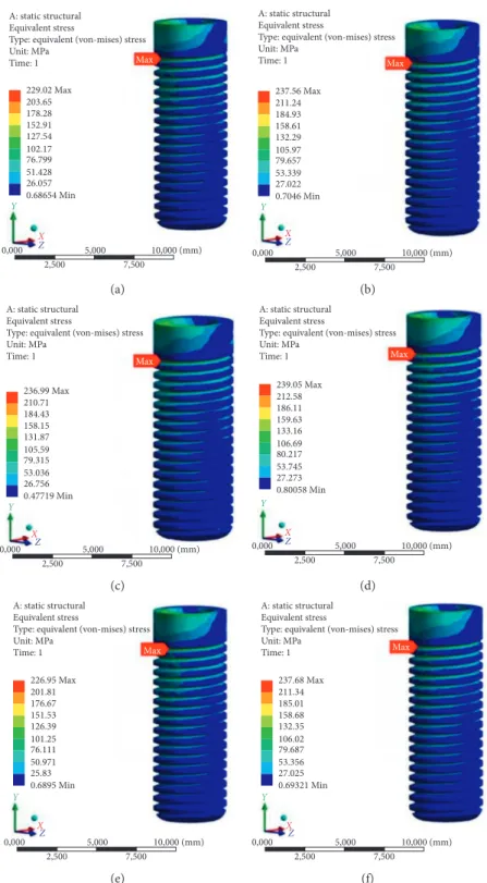
equivalent (von Mises) stress values and their concentrated regions are shown in Figure 3.
It can be obviously seen that the maximum von Mises stresses occurred on the first thread for all the models. Thus, the critical region can also be implied as the first knuckle. It is consistent with the results of the investigation of Wang et al. [45]. Hence, such implants may be predicted to be fractured or have a failure on the related thread region, so it is related directly to the design; however, the design issue is not an objective of this study. It is not a parameter in those FEA because the design of all the models is the same. When the quantitative evaluation is made, the calculated equivalent stress values are observed in the range of 226.95 MPa and 239.05 MPa. They are close to each other relatively since the equivalent stress is dependent on dimensions of the implant, loading types and magnitudes, elastic modulus, and Poisson’s ratio of materials. The same implant dimensions and loading conditions. However, when the FEM theory is considered, it is known that results are generally evaluated in the elastic behavior for static analysis and the stress values are generated according to the basic strength calculations and theories. They are also in re-lation to deformation amount, and the couple terms com-pensate with each other. Herein, the results should be discussed in this approach, and the different but close values may be clarified with this compensation, so the deformation values may be implied as much different for the close stress-induced models. Additionally, when Poisson’s ratio values are considered, the model assigned with YSZ may be interpreted as tending to more transversal deformation than the other ones because its Poisson’s ratio is the highest one among the others. Thus, the first knuckle of this material’s model may probably have the most deformation, so the most equivalent stress value is observed on it.
3.2. Penetration onto the Bone. Separately from the
de-formation, the main constraints are the stress state and cyclic life and also the conformity of the rigidity of implant ma-terials with the bone for this study. In order to provide better
Static structural Time: 1 s Force: 100 N Moment: 300 N∙mm Fixed support A A B B C C Y Z X 2,500 7,500 0,000 5,000 10,000 (mm)
stress transfer from the implant to the bone and avoid the stress-shielding effect, the elastic modulus of the implant is desired to be as close as possible to that of the bone [46]. By this fact, the materials of cp Ti with the nanotubular TiO2
surface, YSZ, and AISI 316L stainless steel become prom-inent since their elastic modulus is relatively low. Also, the lowest elastic modulus value can be seen in nanotubular titania structure. Among the studied materials, this value is the closest one to the value of bone. Moreover, this material caused the highest von Mises stress value on the implant model because its low elastic modulus provides more de-formation on the structure. Thus, this prevents the stress shielding and also provides smooth stress transfer instead of the severe stress transfer to the bone. At this stage, the proximateness of Young’s modulus becomes important. Here, it can be possible to mention about existing different methods to calculate Young’s modulus of cp Ti with the nanotubular TiO2surface. One of them is calculation by an
equation based on the Berkovich indentation technique consisting of contact stiffness, maximum load, and depth [47]. The other one is simpler but useful to have a close value. It is based on the rule of mixtures technique that is used for continuous fiber-reinforced composites generally [48]. It considers the structure as in the isostrain condition or the isostress condition, so the orientation determines Young’s modulus of the composite. Then, it can be implied that Young’s modulus of the cp Ti with the nanotubular TiO2
surface is variable according to the fraction of the nanotubes and the direction. When the adjustment of its tubular structure is considered, Young’s modulus can be adjusted. Thus, it may be thought that nanotubular titania tends to absorb the stress and deform much more relatively. At this point, studying the penetration amounts of the implant models onto the bone becomes appropriate. The bone penetration amounts are shown in Figure 4.
The highest amount of penetration onto the bone structure was calculated on the implant model, in which the material was assigned by cp Ti with nanotubular TiO2
surface, as 0.013626 mm. The lowest value was also calcu-lated on the implant model, in which the material was assigned by L-605 CoCr alloy, as 0.0037389 mm. In view of microscale, the highest result can be assumed as a much penetration value. However, the difference between these extremum penetration amounts is 0.01 mm approximately; hence, just the penetration amount is solely not sufficient for the evaluation. Therefore, However, the surface roughness issue and thus the bone adsorption get importance at this
point. Coelho et al. imply that different methods of implant surface engineering may lead to different and unique surface properties, which might affect the host-to-implant response, and state that the new implant surfaces should be tested and evaluated as new biomaterials [9]. By the principle of the bone healing and growth that can be accelerated and pro-vided by rougher surfaces, the results seem that the materials with the structures of nanotubular and nanoporous may be applicable for manufacturing the implant. However, when their results are evaluated with their unique mechanical properties, the magnitude of the von Mises stress of the model with nanoporous anodic alumina is 237.56 MPa and exceeds its ultimate tensile strength value, and the nanoporous region will probably get damaged, so this material should be studied and developed much more. Thus, the nanotubular titania becomes prominent again according to another fact.
3.3. Fatigue Life Results. The life prediction is based on the
term of the cycle number corresponding to the cyclic stress value. Yona et al. also imply that materials are sought to establish an “infinite” life in the S-N curve under corre-sponding loading condition for dental implants to clear the problem [6]. In Figure 5, the fatigue life prediction results are shown. The S-N curve data found in the literature are based on R � −1, so the solver is run by a loading ratio of R � −1. Cycle results are in the interval of 4 × 10⁵and 1 × 10⁹. For the evaluation of the results, the value of 5 × 10⁶cycles, which is recommended by the guideline of Dental Device Branch of FDA (U.S. Department of Health and Human Services-Food and Drug Administration) [49], can be taken as a reference for meeting the life cycle demand from implants. In this section, the implant modelled with cp Ti with the nano-tubular TiO2surface resulted in a life value of 1 × 10⁷cycles
and CoCr alloy-assigned model resulted in a life of 1 × 10⁹ cycles, so they can also be marked as meeting and even exceeding the reference life requirement. Remaining ma-terials seem not enough for the life criteria for the related implant model.
On the other hand, the implants made of titanium alloys are known as they lead to failure of the treatment due to high cyclic loading that leads to resorption of the peri-implant bone, which increases the bending moments on implants and the metal fatigue, and so the fracture [36]. In contrast to that problem, the bone resorption is predicted to decrease by usage of the nanotubular TiO2surface structure of the cp Ti.
Contrary to the issue again, the bone growth and adsorption Table 1: The properties of materials used in this study.
Material name Density(g/cm3) modulus (GPa)Young’s Poisson’sratio Ultimate tensilestrength (MPa) Referencenumber
AISI 316L stainless steel 8.00 192 0.30 860 [27–29]
Nanoporous anodic alumina 3.96 370 0.22 220 [30, 31]
L-605 CoCr alloy 9.24 240 0.29 1180 [32]
cp Ti with the nanotubular TiO2surface 3.89 40 0.31 640 [33, 34]
Yttrium-stabilized zirconia (YSZ) 6.05 197 0.33 432 [35–37]
Zirconia-toughened alumina (ZTA) 4.10 310 0.26 760 (flexural) [38]
is probably increased; thus, the problem can be overcome. Briefly, the usage of cp Ti with the nanotubular TiO2surface
seems reasonable according to all of the FEA results.
3.4. Thread Number Effect on the Fixation of the Implant.
Consequently, cp Ti with the nanotubular TiO2surface was
evaluated as the best performing material overall according to the conditions in this study. Then, an extra-analysis
about fixation was conducted to understand the effect of the thread numbers on the implant structure. Since the fixation is another issue in the implant system, roughness surface may increase the friction and avoid the loosening of the implant screw. In this section, a method of generating an additional thread was applied to improve the fixation in the implant model. The two- and three-threaded implant de-signs having the same total pitch were developed, and then,
A: static structural Equivalent stress
Type: equivalent (von-mises) stress Unit: MPa Time: 1 Max 229.02 Max 203.65 178.28 152.91 127.54 102.17 76.799 51.428 26.057 0.68654 Min Y X Z 0,000 5,000 2,500 7,500 10,000 (mm) (a) A: static structural Equivalent stress
Type: equivalent (von-mises) stress Unit: MPa Time: 1 Max 237.56 Max 211.24 184.93 158.61 132.29 105.97 79.657 53.339 27.022 0.7046 Min Y X Z 0,000 5,000 2,500 7,500 10,000 (mm) (b) A: static structural Equivalent stress
Type: equivalent (von-mises) stress Unit: MPa Time: 1 Max 236.99 Max 210.71 184.43 158.15 131.87 105.59 79.315 53.036 26.756 0.47719 Min Y X Z 0,000 5,000 2,500 7,500 10,000 (mm) (c) A: static structural Equivalent stress
Type: equivalent (von-mises) stress Unit: MPa Time: 1 Max 239.05 Max 212.58 186.11 159.63 133.16 106.69 80.217 53.745 27.273 0.80058 Min Y X Z 0,000 5,000 2,500 7,500 10,000 (mm) (d) A: static structural Equivalent stress
Type: equivalent (von-mises) stress Unit: MPa Time: 1 Max 226.95 Max 201.81 176.67 151.53 126.39 101.25 76.111 50.971 25.83 0.6895 Min Y X Z 0,000 5,000 2,500 7,500 10,000 (mm) (e) A: static structural Equivalent stress
Type: equivalent (von-mises) stress Unit: MPa Time: 1 Max 237.68 Max 211.34 185.01 158.68 132.35 106.02 79.687 53.356 27.025 0.69321 Min Y X Z 0,000 5,000 2,500 7,500 10,000 (mm) (f)
Figure3: FEA results of implants. Implant materials are AISI 316L stainless steel (a), nanoporous anodic alumina (b), L-605 CoCr alloy (c), cp Ti with the nanotubular TiO2surface (d), YSZ (e), and ZTA (f).
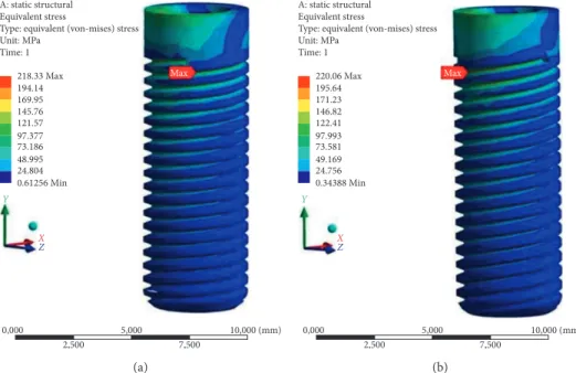
they were analysed to observe the stress amount and the distribution state. The analysis results of the two- and three-threaded designs with the mechanical properties of cp Ti with the nanotubular TiO2 surface are shown in
Figure 6.
These von Mises stress values are close to each other, and they are also reasonable; however, the result of the one-threaded design is 239.05 MPa. It is higher than the results of the multithreaded designs. The stress may be distributed on much more surface than the basic one; therefore, the stress values are resulted lower. On the other hand, the discontinuity due to the more grooves of the multithreads may also lead to notch effect and thus cause unpredictable failure or damage. Hence, this multithreaded design approach should be verified by tests in vitro. Design of sharp thread should be avoided, and the thread angles at the junction region of the implant body should also be reduced as possible. In this context, depth of thread should be
developed for avoiding the interfering of the thread with the bone.
By means of this method, the friction can be increased and the potential failure of implant due to the implant screw loosening may be prevented. Moreover, different from the usage of porous or nanotubular structure, the roughness may also be increased by utilizing multiple threaded design or changing the thread section for getting the mechanical locking between the implant surface and the surrounding bone tissue.
4. Conclusion
The effects of biomaterials on the stress state and fatigue life of dental implants and bone interaction were discussed. Within this scope, various biomaterials, which are appro-priate for implant application, were investigated under cyclic biting loads and the following results were obtained:
A: static structural Penetration Type: penetration Unit: mm Time: 1 Max 0.012151 Max 0.010801 0.009451 0.0081008 0.0067507 0.0054006 0.0040504 0.0027003 0.0013501 0 Min 0,000 5,000 2,500 7,500 10,000 (mm) Y X Z (a) A: static structural Penetration Type: penetration Unit: mm Time: 1 Max 0.011944 Max 0.010617 0.0092897 0.0079626 0.0066355 0.0053084 0.0039813 0.0026542 0.0013271 0 Min 0,000 5,000 2,500 7,500 10,000 (mm) Y X Z (b) A: static structural Penetration Type: penetration Unit: mm Time: 1 Max 0.0037389 Max 0.0033235 0.002908 0.0024926 0.0020772 0.0016617 0.0012463 0.00083087 0.00041543 0 Min 0,000 5,000 2,500 7,500 10,000 (mm) Y X Z (c) A: static structural Penetration Type: penetration Unit: mm Time: 1 Max 0.013626 Max 0.012112 0.010598 0.009084 0.00757 0.006056 0.004542 0.003028 0.001514 0 Min 0,000 5,000 2,500 7,500 10,000 (mm) Y X Z (d) A: static structural Penetration Type: penetration Unit: mm Time: 1 Max 0.012139 Max 0.01079 0.0094416 0.0080928 0.006744 0.0053952 0.0040464 0.0026976 0.0013488 0 Min 0,000 5,000 2,500 7,500 10,000 (mm) Y X Z (e) A: static structural Penetration Type: penetration Unit: mm Time: 1 Max 0.011983 Max 0.010651 0.0093199 0.0079885 0.0066571 0.0053257 0.0039943 0.0026628 0.0013314 0 Min 0,000 5,000 2,500 7,500 10,000 (mm) Y X Z (f)
Figure4: Bone penetration results of implants. Implant materials are AISI 316L stainless steel (a), nanoporous anodic alumina (b), L-605 CoCr alloy (c), cp Ti with the nanotubular TiO2surface (d), YSZ (e), and ZTA (f).
(i) The mechanical properties of implant materials cause stress distribution on the implant. Especially, the elastic modulus affects the stress magnitude and distribution. Moreover, Poisson’s ratio is another factor that influences the terms, but it is in a mutual relation with the elastic modulus. They change the deformation and stress together.
(ii) When the elastic modulus of an implant converges to the bone numerically, any applied load leads to stress and much more deformation on the implant. This fact provides smooth transmission of the stress from the implant to the bone and also decreases the
transmitted energy magnitude. Therefore, the im-plant and the bone interaction becomes smooth. It may be evaluated that this case leads to more de-formation in both implant and bone tissue. However, this fact may also be evaluated as less bone damaging, since the implant is not rigid much more and so it leads less pulverization of bone.
(iii) However, the decrease of the elasticity leads to increase of the implant to bone penetration due to the increase in the deformation of the implant. Thus, it should also be recommended to research the medical interaction in this phenomenon.
A: static structural Life Type: life Time: 0 3e6 Max 3e5 30000 3000 300 30 3 0.3 0.03 0 Min 0,000 5,000 2,500 7,500 10,000 (mm) Y X Z (a) A: static structural Life Type: life Time: 0 1e6 Max 1e5 10000 1000 100 10 1 0.1 0.01 0 Min 0,000 5,000 2,500 7,500 10,000 (mm) Y X Z (b) A: static structural Life Type: life Time: 0 1e9 Max 1e8 1e7 1e6 1e5 10000 1000 100 10 0 Min 0,000 5,000 2,500 7,500 10,000 (mm) Y X Z (c) A: static structural Life Type: life Time: 0 1e7 Max 1e6 1e5 10000 1000 100 10 1 0.1 0 Min 0,000 5,000 2,500 7,500 10,000 (mm) Y X Z (d) A: static structural Life Type: life Time: 0 4e5 Max 40000 4000 400 40 4 0.4 0.04 0.004 0 Min 0,000 5,000 2,500 7,500 10,000 (mm) Y X Z (e) A: static structural Life Type: life Time: 0 5e5 Max 50000 5000 500 50 5 0.5 0.05 0.005 0 Min 0,000 5,000 2,500 7,500 10,000 (mm) Y X Z (f)
Figure5: Fatigue life results of implants. Implant materials are AISI 316L stainless steel (a), nanoporous anodic alumina (b), L-605 CoCr alloy (c), cp Ti with the nanotubular TiO2surface (d), YSZ (e), and ZTA (f).
(iv) To provide more fixation, the friction must be in-creased. For this reason, the multiple threaded designs may also be a solution to obtain required mechanical locking between the implant surface and the surrounding bone.
(v) The nanoporous/nanotubular TiO2 dental implant
having multiple threaded designs may supply the needs of implantation technology. It has similar elastic mod-ulus with bone tissue, and this provides smooth stress transformation from implant to bone. The nanoporous surface and the multiple threaded design increase the surface roughness and the friction. Hence, the fixation of the implant can be increased, and the bone growth on the surface of the implant can be supported. This im-plant can also display long-term stability under cyclic biting loads due to its novel design and its high strength.
Conflicts of Interest
The authors declare that there are no conflicts of interest regarding the publication of this paper.
References
[1] F. Bodic, L. Hamel, E. Lerouxel, M. F. Basle, and D. Chappard, “Bone loss and teeth,” Joint Bone Spine, vol. 72, no. 3, pp. 215–221, 2005.
[2] B. Guillaume, “Dental implants: a review,” Morphologie, vol. 100, no. 331, pp. 189–198, 2016.
[3] F. Javed and G. E. Romanos, “The role of primary stability for successful immediate loading of dental implants. A literature review,” Journal of Dentistry, vol. 38, no. 8, pp. 612–620, 2010. [4] P. Bicudo, J. Reis, A. M. Deus, L. Reis, and M. F. Vaz, “Mechanical behaviour of dental implants,” Procedia
Struc-tural Integrity, vol. 1, pp. 26–33, 2016.
[5] S. Suresh, “Stress–life approach,” in Fatigue of Materials, Cambridge University Press, Cambridge, UK, 2nd edition, 1998.
[6] K. S. Yona and D. Rittel, “Fatigue of dental implants: facts and fallacies,” Dentistry Journal, vol. 4, no. 2, p. 16, 2016. [7] F. Lofaj, J. Kucera, D. Nemeth, and L. Kvetkova, “Finite
el-ement analysis of stress distributions in mono- and bi-cortical dental implants,” Materials Science and Engineering C, vol. 50, pp. 85–96, 2015.
[8] A. B. Novaes Jr., S. L. S. Souza, R. R. M. Barros, K. K. Y. Pereira, G. Iezzi, and A. Piattelli, “Influence of im-plant surfaces on osseointegration,” Brazilian Dental Journal, vol. 21, no. 6, pp. 471–481, 2010.
[9] P. G. Coelho, J. M. Granjeiro, G. E. Romanos et al., “Basic research methods and current trends of dental implant sur-faces,” Journal of Biomedical Materials Research Part B:
Ap-plied Biomaterials, vol. 88, no. 2, pp. 579–596, 2009.
[10] C. N. Elias, D. J. Fernandes, C. R. S. Resende, and J. Roestel, “Mechanical properties, surface morphology and stability of a modified commercially pure high strength titanium alloy for dental implants,” Dental Materials, vol. 31, no. 2, pp. 1–13, 2015.
[11] J. Chen, C. Rungsiyakull, W. Li, Y. Chen, M. Swain, and Q. Li, “Multiscale design of surface morphological gradient for osseointegration,” Journal of the Mechanical Behavior of
Biomedical Materials, vol. 20, pp. 387–397, 2013.
[12] E. D. Spoerke, N. G. Murray, H. Li, L. C. Brinson, D. C. Dunand, and S. I. Stupp, “A bioactive titanium foam scaffold for bone repair,” Acta Biomaterialia, vol. 1, no. 5, pp. 523–533, 2005. [13] C. M. Abraham, “A brief historical perspective on dental
implants, their surface coatings and treatments,” Open
Dentistry Journal, vol. 8, no. 1, pp. 50–55, 2014.
[14] Zimmer Biomet, Dental, http://www.zimmerdental.com/ library/lib_techtipsfaq.aspx, 2017.
[15] M. B. Ferreira, V. A. Barao, J. A. Delben, L. P. Faverani, A. C. Hipolito, and W. G. Assuncao, “Non-linear 3D finite element analysis of full-arch implant-supported fixed dentures,”
Materials Science and Engineering C, vol. 38, pp. 306–314, 2014.
A: static structural Equivalent stress
Type: equivalent (von-mises) stress Unit: MPa Time: 1 218.33 Max 194.14 169.95 145.76 121.57 97.377 73.186 48.995 24.804 0.61256 Min 0,000 5,000 2,500 7,500 10,000 (mm) Max Y X Z (a) A: static structural Equivalent stress
Type: equivalent (von-mises) stress Unit: MPa Time: 1 220.06 Max 195.64 171.23 146.82 122.41 97.993 73.581 49.169 24.756 0.34388 Min 0,000 5,000 2,500 7,500 10,000 (mm) Max Y X Z (b)
[16] B. C. Spies, C. Sauter, M. Wolkewitz, and R. J. Kohal, “Alumina reinforced zirconia implants: effects of cyclic loading and abutment modification on fracture resistance,”
Dental Materials, vol. 31, no. 3, pp. 262–272, 2015.
[17] M. A. L. H. Rodriguez, G. R. C. Hernandez, A. J. Hernandez, B. B. Ramirez, and E. G. Sanchez, “Failure analysis in a dental implant,” Engineering Failure Analysis, vol. 57, pp. 236–242, 2015.
[18] M. H. Fathi, M. Salehi, A. Saatchi, V. Mortazavi, and S. B. Moosavi, “In vitro corrosion behaviour of bioceramic, metallic, and bioceramic-metallic coated stainless steel dental implants,” Dental Materials, vol. 19, no. 3, pp. 188–198, 2003. [19] L. Hjalmarsson, On Cobalt-Chrome Frameworks in Implant
Dentistry, Geson Hylte Tryck, G¨oteborg, Sweden, 2009.
[20] G. Maccauro, P. R. Iommetti, L. Raffaelli, and P. F. Manicone, “Alumina and zirconia ceramic for orthopaedic and dental devices,” in Biomaterials applications for Nanomedicine, R. Pignatello, Ed., InTech, Rijeka, Croatia, 2011.
[21] J. J. Klawitter, A. M. Weinstein, F. W. Cooke, L. J. Peterson, B. M. Pennel, and R. V. McKinney Jr., “An evaluation of porous alumina ceramic dental implants,” Journal of Dental
Research, vol. 56, no. 7, pp. 768–776, 1977.
[22] R. B. Osman and M. V. Swain, “A critical review of dental implant materials with an emphasis on titanium versus zir-conia,” Materials, vol. 8, no. 3, pp. 932–958, 2015.
[23] G. S. Kaliaraj, M. Bavanilathamuthiah, K. Kirubaharan et al., “Bioinspired YSZ coated titanium by EB PVD for biomedical applications,” Surface and Coatings Technology, vol. 307, pp. 227–253, 2016.
[24] X. He, Y. Z. Zhang, J. P. Mansell, and B. Su, “Zirconia toughened alumina ceramic foams for potential bone graft applications: fabrication, bioactivation, and cellular re-sponses,” Journal of Materials Science: Materials in Medicine, vol. 19, no. 7, pp. 2743–2749, 2008.
[25] S. M. Kurtz, S. Kocagoz, C. Arnholt, R. Huet, M. Ueno, and W. L. Walter, “Advances in zirconia toughened alumina biomaterials for total joint replacement,” Journal of the
Me-chanical Behavior of Biomedical Materials, vol. 31, pp. 107–
116, 2014.
[26] C. N. Elias, J. H. C. Lima, R. Valiev, and M. A. Meyers, “Biomedical applications of titanium and its alloys,” JOM, vol. 60, no. 3, pp. 46–49, 2008.
[27] B. Gervais, A. Vadean, M. Raison, and M. Brochu, “Failure analysis of a 316L stainless steel femoral orthopedic implant,”
Case Studies in Engineering Failure Analysis, vol. 5-6,
pp. 30–38, 2016.
[28] L. H. Timmins, C. A. Meyer, M. R. Moreno, and J. E. Moore, “Effects of stent design and atherosclerotic plaque composi-tion on arterial wall biomechanics,” Journal of Endovascular
Therapy, vol. 15, no. 6, pp. 643–654, 2008.
[29] M. McCracken, “Dental implant materials: commercially pure titanium and titanium alloys,” Journal of Prosthodontics, vol. 8, no. 1, pp. 40–43, 1999.
[30] T. H. Fang, T. H. Wang, C. H. Liu, L. W. Ji, and S. H. Kang, “Physical behavior of nanoporous anodic alumina using nanoindentation and microhardness tests,” Nanoscale
Re-search Letters, vol. 2, no. 8, pp. 410–415, 2007.
[31] K. Davis, “Material review: alumina (Al2O3),” School of
Doctoral Studies (European Union) Journal, vol. 2, pp. 109–
114, 2010.
[32] ASM Materials for Medical Devices Database Committee,
Materials and Coatings for Medical Devices: Cardiovascular,
ASM International, Geauga County, OH, USA, 2009.
[33] S. Sobieszczyk and R. Klotzke, “Nanotubular titanium oxide layers for enhancement of bone-implant bonding and bio-activity,” Advances in Materials Sciences, vol. 11, no. 1, pp. 17–26, 2011.
[34] T. Yoshimura, H. Imai, T. Threrujirapapong, and K. Kondoh, “Cost effective pure titanium with high mechanical response by oxide dispersion strengthening,” Materials Transactions, vol. 50, no. 12, pp. 2751–2756, 2009.
[35] M. Oishi, Y. Matsuda, K. Noguchi, and T. Masaki, “Evaluation of tensile strength and fracture toughness of yttria-stabilized zirconia polycrystals with fracture surface analysis,” Journal of
the American Ceramic Society, vol. 78, no. 5, pp. 1212–1216,
1995.
[36] K. Noguchi, Y. Matsuda, M. Oishi, T. Masaki, S. Nakayama, and M. Mizushina, “Strength analysis of yttria-stabilized te-tragonal zirconia polycrystals,” Journal of the American
Ce-ramic Society, vol. 73, no. 9, pp. 2667–2676, 1990.
[37] S. Y. Liu and I. W. Chen, “Fatigue of yttria-stabilized zirconia: I, fatigue damage, fracture origins, and lifetime prediction,”
Journal of the American Ceramic Society, vol. 74, no. 6,
pp. 1197–1205, 1991.
[38] K. J. Anusavice, C. Shen, and H. R. Rawls, Phillips’ Science of
Dental Materials, Elsevier, Amsterdam, Netherlands, 12th
edition, 2012.
[39] M. Sevimay, A. Usumez, and G. Eskitascıoglu, “The influence of various occlusal materials on stresses transferred to implant-supported prostheses and supporting bone: a three dimensional finite-element study,” Journal of Biomedical
Materials Research Part B: Applied Biomaterials, vol. 73, no. 1,
pp. 140–147, 2005.
[40] H. E. Boyer, Atlas of Fatigue Curves, ASM International, Geauga County, OH, USA, 1986.
[41] R. Nejma, K.-H. Lang, and D. Lohe, “Isothermal and thermal-mechanical fatigue of alumina,” Materialwissenschaft und
Werkstofftechnik, vol. 36, no. 3-4, pp. 136–139, 2005.
[42] R. V. Marrey, R. Burgermeister, R. B. Grishaber, and R.O. Ritchie, “Fatigue and life prediction for cobalt-chromium stents: a fracture mechanics analysis,” Biomaterials, vol. 27, no. 9, pp. 1988–2000, 2006.
[43] F. Guiu, M. J. Reece, and D. A. J. Vaughan, “Cyclic fatigue of ceramics,” Journal of Materials Science, vol. 26, no. 12, pp. 3275–3286, 1991.
[44] T. Soma, M. Masuda, M. Matsui, and I. Oda, “Cyclic fatigue testing of ceramic materials,” International Journal of High
Technology Ceramics, vol. 4, no. 2–4, pp. 289–299, 1988.
[45] K. Wang, J. Geng, D. Jones, and W. Xu, “Comparison of the fracture resistance of dental implants with different abutment taper angles,” Materials Science and Engineering C, vol. 63, pp. 164–171, 2016.
[46] M. Niinomi and M. Nakai, “Titanium-based biomaterials for preventing stress shielding between implant devices and bone,” International Journal of Biomaterials, vol. 2011, Article ID 836587, 10 pages, 2011.
[47] W. Y. Chang, T. H. Fang, Z. W. Chiu, Y. J. Hsiao, and L. W. Ji, “Nanomechanical properties of array TiO2nanotubes,”
Mi-croporous and Mesoporous Materials, vol. 145, no. 1–3,
pp. 87–92, 2011.
[48] G. A. Crawford, N. Chawla, K. Das, S. Bose, and A. Bandyopadhyay, “Microstructure and deformation behavior of biocompatible TiO2nanotubes on titanium substrate,” Acta Biomaterialia,
vol. 3, no. 3, pp. 359–367, 2007.
[49] Food and Drug Administration, 2004 http://www.fda.gov/ RegulatoryInformation/Guidances/ucm072424.htm#4.
Corrosion
International Journal of
Hindawi
www.hindawi.com Volume 2018
Advances in
Materials Science and Engineering Hindawi www.hindawi.com Volume 2018 Hindawi www.hindawi.com Volume 2018 Journal of
Chemistry
Analytical Chemistry International Journal of Hindawi www.hindawi.com Volume 2018Scientifica
Hindawi www.hindawi.com Volume 2018Polymer Science
International Journal of Hindawiwww.hindawi.com Volume 2018
Hindawi
www.hindawi.com Volume 2018
Advances in
Condensed Matter Physics
Hindawi www.hindawi.com Volume 2018 International Journal of
Biomaterials
Hindawi www.hindawi.com Journal ofEngineering
Volume 2018Applied Chemistry
Journal ofHindawi www.hindawi.com Volume 2018
Nanotechnology
Hindawi www.hindawi.com Volume 2018 Journal of Hindawi www.hindawi.com Volume 2018High Energy PhysicsAdvances in
Hindawi Publishing Corporation
http://www.hindawi.com Volume 2013 Hindawi www.hindawi.com