Full Terms & Conditions of access and use can be found at
https://www.tandfonline.com/action/journalInformation?journalCode=ueht20
Experimental Heat Transfer
A Journal of Thermal Energy Generation, Transport, Storage, and
Conversion
ISSN: (Print) (Online) Journal homepage: https://www.tandfonline.com/loi/ueht20
Experimental and numerical investigation of
diffusion absorption refrigeration system working
with ZnOAl
2
O
3
and TiO
2
nanoparticles added
ammonia/water nanofluid
Emine Yağız Gürbüz , Adnan Sözen , Ali Keçebaş & Engin Özbaş
To cite this article: Emine Yağız Gürbüz , Adnan Sözen , Ali Keçebaş & Engin Özbaş (2020): Experimental and numerical investigation of diffusion absorption refrigeration system working with ZnOAl2O3 and TiO2 nanoparticles added ammonia/water nanofluid, Experimental Heat Transfer, DOI: 10.1080/08916152.2020.1838668
To link to this article: https://doi.org/10.1080/08916152.2020.1838668
Published online: 03 Nov 2020.
Submit your article to this journal
Article views: 28
View related articles
Experimental and numerical investigation of diffusion absorption
refrigeration system working with ZnOAl
2O
3and TiO
2nanoparticles added ammonia/water nanofluid
Emine Yağız Gürbüza,b, Adnan Sözen c, Ali Keçebaşa, and Engin Özbaş d
aDepartment of Energy Systems Engineering, Technology Faculty, Muğla Sıtkı Koçman University, Muğla, Turkey; bNatural and Applied Science Institute, Gazi University, Ankara, Turkey; cDepartment of Energy Systems Engineering,
Technology Faculty, Gazi University, Ankara, Turkey; dYeşilyurt Demir Çelik Vocational School, Ondokuz Mayıs
University, Samsun, Turkey ABSTRACT
In this paper, the effect of various zinc oxide aluminate spinel (ZnOAl2O3) and
titanium oxide (TiO2) nanoparticle concentrations on the thermal
perfor-mance of the Diffusion Absorption Refrigeration (DAR) system is investi-gated. The main aim of the study is to increase the efficiency of DAR systems operating with low thermal performance. The first part of the study is experimentally tested on the system under the same ambient conditions in order to develop passive heat transfer using different nano-fluids as working liquids, including ammonia/water solution containing dif-ferent amounts (1 wt.% and 2 wt.%) of ZnOAl2O3 and TiO2 particles. In the
next part of the study, the tested system is designed in MATLAB/Simulink toolbox environment to compare experimental and numerical results. The use of nanofluids can increase the surface area expansion and the heat capacity of the fluid, resulting in a significant positive increase in heat transfer. The results clarify that the use of nanofluid as working fluid in the DAR system helps quicker evaporation, which reduces operating time and increases heat transfer in the generator. Compared to a base DAR system, the nanofluid solution with a 2 wt.% ZnOAl2O3 nanoparticle concentration
among other nanofluid and proportions causes a 57% increase in the coeffi-cient of performance (COP) of DAR system.
ARTICLE HISTORY
Received 8 June 2020 Accepted 13 October 2020
KEYWORDS
Diffusion absorption refrigeration; nanofluid; zinc oxide aluminate spinel; titanium oxide; thermal performance
Introduction
Diffusion absorption cycles (DARs) for refrigeration or air-conditioning systems have recently to attracted great attention. Due to 7% of global energy consumption is related to cooling processes [1]. Moreover, while some researchers are expected to double their space cooling capacity by 2025, Asian countries’ demand for energy makes them the dominant energy consumers in cooling [2, 3]. In relation to this increasing demand, conventional refrigeration systems (vapor-compression refrigera-tion systems) are being developed to operate with renewable energy inputs as a hybrid cooling systems [4]. However, hybrid systems can harmful to the environment due to the depletion of the ozone layer and the effects of greenhouse emissions. Therefore, DAR systems have some important advantages that reduce greenhouse emissions and other harmful effects on the environment.
DAR can be defined as one of the absorption cycles, which is quite useful with its distinct advantages especially in small-scale applications [5]. It only refers to a single pressure” cycle in
CONTACT Emine Yağız Gürbüz [email protected] Department of Energy Systems Engineering, Technology Faculty, Muğla Sıtkı Koçman University, Muğla, Turkey
AbbreviationsDAR:diffusion absorption refrigeration, dimensionless; DMAC:dimethylacetamide; GHXgas heat exchanger; SDBS: sodium dodecyl benzenesulfonates; SHX:solution heat exchanger; TiO2:titanium oxide; ZnOAl2O3:zinc oxide aluminate spinel
EXPERIMENTAL HEAT TRANSFER https://doi.org/10.1080/08916152.2020.1838668
which the circulation of the working fluid can provide with a bubble pump (thermally driven), so no electrical input is required for circulating the working fluid. Also, DAR system contains a compensating gas, which can be helium or hydrogen, that helps the evaporation process by reducing the partial pressure of the refrigerant in the evaporator part. Generally, the DAR systems are commonly used in recreational vehicles, campers, hotels, and caravans because they can be powered with propane fuel, rather than electricity. In addition to this advantage, low noise levels, low construction and maintenance costs are other advantages of the DAR system. However, a typical low performance problem exists with the DAR systems. There are many methods to overcome this problem, including adding ejector [6–9], changing cycle streamlines [10, 11], or changing working fluid [12, 13]. Thus, the different studies conducted on DAR by the researchers can be summarized in
Table 1.
To overcome the low coefficient of performance (COP) barrier, new techniques, and new materials need to work in a number of roles. Furthermore, low-cost methods have been developed to increase thermal conductivity of coolant. Therefore, in recent studies, nanofluid containing nanoscale metal/ mineralogical materials has been used instead of traditional working fluids [27, 28]. Nanofluids can be defined as suspension solutions of a nanoscale material with better thermodynamic properties than conventional working pairs [29].
The use of organic refrigerants and nanofluids is becoming popular in the DAR system. Zohar et al. [30] conducted a study with organic absorbent (DMAC, dimethylacetamide) and five different refrigerants, R134a, R124, R125, R32, and R22. In the study, helium was used as an inert gas. Their results indicated that the boiling point of the liquid pairs was lower than the conventional working fluid (ammonia-water). Also, utilizing nanoparticles lead to in a notable decrease in working fluid flow rate, and this advantage affect the whole system from different aspects [31]. Lower working fluid flow rate was also of decreasing the amount of pumping power which lead to consuming less energy [32,
33]. An extensive study was done by Yang et al. [22] to find proper nanofluid applied to the DARs for enhancing overall system performance and they worked 20 types of nanoparticles and 10 types of surface active agents in a NH3-H2O solution, respectively. They obtained particularly TiO2, TiN, and
SiC nanoparticles show fine dispersion stabilities in the base solution. Wu et al. [23] experimentally investigated the increasing influence of nanoparticles on an ammonia/water falling film absorption process. Other recent study was done by Aramesh et al. [24]. investigated the effects of employing nanofluids as a working fluid in a double-effect absorption refrigeration cycle with a solar trough collector. After testing four different nanoparticles (Ag, Cu, CuO, Al2O3), results showed the best
performance was obtained with the Ag nanoparticles (2.5% concentration) by 53%. Moreover, Jiang
et al. [25] conducted a study on an absorption refrigeration system with a newly designed absorber and adding TiO2 nanoparticles to the working fluid. The obtained results of this study indicated that the
nanofluids thermal conductivity dominates the absorption refrigeration process. Furthermore, same researchers investigated the dynamic characteristics (suspending ability, surface tension and viscosity) of NH3-H2O-based TiO2 nanofluids in the absorption refrigeration system. The results indicated that
the dynamic circulating process can greatly increase the suspending ability of nanofluid [26]. It is important to highlight that most studies on a commercial DAR system analyze the COP from the point of thermodynamics, some others indicate that adding nanoparticles to the base fluid is a good way to enhance the absorption performance [34]. However, none of this studies investigates a DAR system without the condensate subcooling as recommended in Zohar et al. [18]. This is why this article presents a newly designed DAR and investigates the effect of using nanofluids on the thermal performance of the DAR system. In this study, in the first step, the newly designed DAR system is introduced and also thermodynamic parameters of the new system are given briefly. The ammonia-water-based nanofluids (1% TiO2, 2% TiO2, 1% ZnOAl2O3, and 2%
ZnOAl2O3) have been employed as a working fluid for enhancing of COP in the DAR system and
obtained results have been evaluated on overall system performance. Next, the proposed DAR system in the present work has been designed simply in the MATLAB/Simulink toolbox environ-ment. In this section, simulation results were compared to obtained experimental results in order
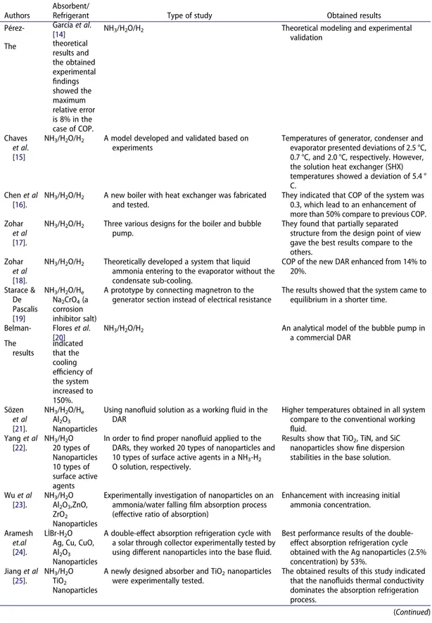
Table 1. A summary of the studies done on improving the performance of the DAR system.
Authors
Absorbent/
Refrigerant Type of study Obtained results Pérez- García et al.
[14] NH3/H2O/H2 Theoretical modeling and experimental validation The theoretical results and the obtained experimental findings showed the maximum relative error is 8% in the case of COP. Chaves et al. [15]
NH3/H2O/H2 A model developed and validated based on
experiments
Temperatures of generator, condenser and evaporator presented deviations of 2.5 °C, 0.7 °C, and 2.0 °C, respectively. However, the solution heat exchanger (SHX) temperatures showed a deviation of 5.4 ° C.
Chen et al [16].
NH3/H2O/H2 A new boiler with heat exchanger was fabricated
and tested.
They indicated that COP of the system was 0.3, which lead to an enhancement of more than 50% compare to previous COP. Zohar
et al
[17].
NH3/H2O/H2 Three various designs for the boiler and bubble
pump.
They found that partially separated structure from the design point of view gave the best results compare to the others.
Zohar
et al
[18].
NH3/H2O/H2 Theoretically developed a system that liquid
ammonia entering to the evaporator without the condensate sub-cooling.
COP of the new DAR enhanced from 14% to 20%. Starace & De Pascalis [19] NH3/H2O/He Na2CrO4 (a corrosion inhibitor salt)
A prototype by connecting magnetron to the generator section instead of electrical resistance
The results showed that the system came to equilibrium in a shorter time.
Belman- Flores et al. [20]
NH3/H2O/H2 An analytical model of the bubble pump in
a commercial DAR The results indicated that the cooling efficiency of the system increased to 150%. Sözen et al [21]. NH3/H2O/He Al2O3 Nanoparticles
Using nanofluid solution as a working fluid in the DAR
Higher temperatures obtained in all system compare to the conventional working fluid. Yang et al [22]. NH3/H2O 20 types of Nanoparticles 10 types of surface active agents
In order to find proper nanofluid applied to the DARs, they worked 20 types of nanoparticles and 10 types of surface active agents in a NH3-H2
O solution, respectively.
Results show that TiO2, TiN, and SiC
nanoparticles show fine dispersion stabilities in the base solution.
Wu et al [23]. NH3/H2O Al2O3,ZnO, ZrO2 Nanoparticles
Experimentally investigation of nanoparticles on an ammonia/water falling film absorption process (effective ratio of absorption)
Enhancement with increasing initial ammonia concentration.
Aramesh
et.al
[24].
LİBr-H2O
Ag, Cu, CuO, Al2O3
Nanoparticles
A double-effect absorption refrigeration cycle with a solar through collector experimentally tested by using different nanoparticles into the base fluid.
Best performance results of the double- effect absorption refrigeration cycle obtained with the Ag nanoparticles (2.5% concentration) by 53%. Jiang et al [25]. NH3/H2O TiO2 Nanoparticles
A newly designed absorber and TiO2 nanoparticles
were experimentally tested.
The obtained results of this study indicated that the nanofluids thermal conductivity dominates the absorption refrigeration process.
(Continued) EXPERIMENTAL HEAT TRANSFER 3
to provide detailed information for optimum working conditions. Moreover, this evaluation gives the chance to compare parameters of the proposed DAR system. Lastly, there were slightly higher COP values indicated in simulation results, however the difference between the experimental results and simulation results ranged from 1% to 5% caused by increasing nanoparticle ratios in the solution.
System description and experimental apparatus
Definition of the experimental set-up and working principle of the DAR system
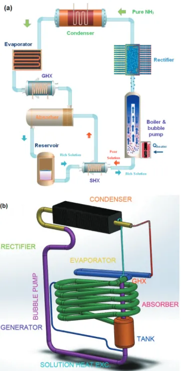
In this study, a DAR system without the condensate subcooling was manufactured, and added nanofluids to the newly designed DAR in order to enhance the thermal performance of the refrigerator. A generator-bubble pump, a rectifier, a condenser, a gas heat exchanger (GHX), an evaporator, an absorber, and a solution heat exchanger (SHX) are the main parts of the DAR system.
The schematic diagrams of the DAR system and a refrigerator are shown in Figure 1. As it can be seen in Figure 1, the rich ammonia and water solution in the reservoir flows into the SHX and then goes through to the generator, where ammonia evaporates from the solution via heat by generator. During this process, the ammonia vapor mixture also pushes a small amount of water and rises together to the bubble pump. The mixture is separated in the top of the bubble pump, and an amount of weak ammonia solution goes through to outer of the pipe. However, ammonia vapor still contains a liquid solution and flows through to the rectifier. The main aim of using the rectifier is to deliver pure ammonia vapor to the condenser. Thus, the water vapor condenses again in the rectifier part. After rectifier section, the pure ammonia vapor reaches to the condenser and releases to heat.
In a commercial DAR system, the condensed ammonia goes to the condensate ammonia tube for subcooling process before the evaporator [35]. However, this system does not have a subcooling process as mentioned earlier. In the system, the liquid ammonia enters to the evaporator directly. A notably reduction in the partial pressure of liquid ammonia at the inlet of the evaporator is measured due to mixing with the cold helium and ammonia vapor. As a result, the partial pressure of liquid ammonia and the temperature are reduced in the evaporator part, resulting in a cooling effect. The liquid refrigerant and ammonia-helium mixture moves in parallel through the evaporator/ GHX under the influence of gravity. At the absorber inlet, a weak ammonia solution enters to the absorber, where ammonia begins to condense and separate from the helium, removing heat. Helium and ammonia residuals return to the evaporator, and rich ammonia water solution flows down in the reservoir as a working fluid.
Preparation of ZnOAl2O3 and TiO2 as a nanofluid
Choi & Eastman [36] introduced the nanofluids concept for the first time in 1995. This concept refers a suspension consists of a base fluid and some nanoparticles. By this invention, nanofluids have been used many applications of heat transfer processes. Particularly, the most notable property of nano-fluids is thermal conductivity. Utilizing nanoparticles into the base fluid increase thermal conductivity of the working fluid and also this lead an enhancement in heat transfer. After the advantages of nanofluids were demonstrated, researchers started to use multiple nanoparticles simultaneously in Table 1. (Continued).
Authors
Absorbent/
Refrigerant Type of study Obtained results Yang et al
[26].
NH3/H2O
TiO2
Nanoparticles
A device was constructed to find out the dynamic characteristics of nanofluid solution.
The dynamic circulating process can greatly increase the suspending ability of nanofluid.
a base fluid, in order to increase benefits of nanoparticles with several different nanoparticles. This type of nanofluid was called hybrid nanofluid. Hybrid nanofluids have higher thermal-conductivity than mono nanofluids [37].
In this study, five various working fluids with same volume are tested for the newly DAR system. Two of working fluids consist of 1% and 2% concentrations of TiO2 nanoparticles into the ammonia/
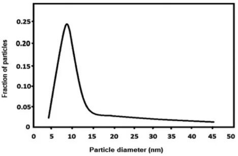
water solution (25%) that are mono nanofluids. TiO2 nanoparticles with an average sizes of 14 nm are
Figure 1. A schematic view of (a) the DAR system and (b) its refrigerator.
utilized to prepare the mono nanofluid (see Figure 2). There are numerous studies by using TiO2
nanoparticles into a base fluid due to their cheap price and convenient purchases [38]. Also, a study displayed that the thermal conductivity of nanofluid increase to 15.4% by using TiO2 nanoparticles
[39]. Thus, it is clear that utilizing TiO2 nanoparticles with an average sizes of 14 nm may make
a significant enhancement in the DAR system.
Other two working fluids consist of 1% and 2% concentrations of ZnOAl2O3 nanoparticles which is
a good choice for hybrid nanoparticles, has been prepared to be used in the DAR system (see Figure 3). In a study done by Mukherjee et al. [40] indicated that Al2O3 nanoparticle addition is advantageous
over TiO2 nanoparticle addition in base fluids. In this study, Al2O3 nanoparticles are also mixed with
ZnO nanoparticles, thus it leads better results in terms of thermophysical properties.
The nanoparticle concentrations are prepared for use in nanofluid with a nanoparticle content of 2% and 1% (wt/wt). Then, prepared nanoparticles are added into the ammonia/water as the base fluid. In this preparation stage, a surfactant must be added to the system due to reduce the interaction Figure 2. Average sizes of TiO2nanoparticles.
between the particles and activate the repulsion forces in order to maintain stability of the nanopar-ticles [26, 41]. The suspensions are enhanced by adding Triton X-100 surface-active agent of 0.5% (wt./ wt.). Triton X-100 was originally a registered trademark of Rohm and Haas Co. Triton X-100 (the closed molecular formula) is C14H22O(C2H4O)n as a nonionic and clear viscous fluid surfactant.
Lastly, other essential part of preparation started with ultrasonic bath. The ultrasonic bath should be maintained for at least three hours for each solution. Consequently, TiO2 and ZnOAL2O3
nanopar-ticles can be suspended in the base fluid for a longer time by means of ultrasonic bath and surfactant addition.
Experimental apparatus
A DAR system without the condensate subcooling has seven parts: a generator-bubble pump, a rectifier, a condenser, a GHX, an evaporator, an absorber and a SHX. In a commercial Dar system consists of the same components, however there is a subcooling process after condensate process. The Figure 4. Experimental apparatus of the DAR system.
base fluid (ammonia-water of 25%) with a volume of 250 ml is charged into the system as a working fluid from the charging point. After charging process, the designed DAR pressurized with helium at the charging pressure of 13.5–14 bar. Also, the generator-bubble pump part of the system is isolated to reduce the heat losses in the DAR system (see Figure 4). As seen in Figure 4, pressure value of the DAR is taken from one point which was the inlet point of the condenser by pressure transmitter in full scale of 0–20 bar with an accuracy of ±1%. Moreover, the ambient temperature and pressure during the tests are measured. For each test, each nanofluid solution is prepared separately due to system has to be emptied after a solution experimentally tested. Thus, five different solutions are prepared and charged from the point seen in Figure 4. Also, inert gas (helium) is also charged to the system before every experiment section.
During the experiments, it is seen that the system becomes steady-state especially after 120 minutes and then it stops in 180 minutes. Experiments are repeated five times for each nanofluid to obtain more accurate results. After base fluid tests, the concentration of 1% nanofluid solutions of ZnOAl2O3
and the concentration of 1% nanofluid solutions of TiO2 are filled into the DAR system and then tested
for 180 minutes, respectively. Also these nanofluid tests are repeated five times for accuracy. In the last step of the experiments, the concentrations of 2% nanofluid solutions of ZnOAl2O3 and 2% nanofluid
solutions of TiO2 are utilized as a working fluid in the DAR system, respectively. In all the
experi-ments, the ambient conditions set same during the experiments in order to compare the results with each other meaningfully. Thus, the generator power of the DAR system is supplied with a constant value of 75 kW. For measuring the system power, a wattmeter (Fluke-43b analyzer) with an accuracy of ±0.1 kWh is used.
For each test section, nine different temperature values are measured and recorded with a data- logger (see Figure 4). Three of them are from generator-bubble pump section: the generator inlet point (T7), the generator point of weak solution (T1b), the bubble pump outlet point (T1c). The rectifier
outlet point (T2) and the condenser outlet point (T3) are in rectifier and condenser sections,
respectively. Three points from the evaporator part are the evaporator inlet points (T4a–T4c), the
evaporator outlet point (T5). The K-type thermocouples with a precision of ±0.1°C are placed to these
temperature points.
Thermodynamic analysis
Energy analysis
In this study, a thermodynamic model is suggested for the analysis of the newly DAR system described in Section 2. Thermodynamic analysis, referring to the first of law thermodynamics control volumes of each part of a DAR cycle adapted from Zohar et al. [18]. are defined firstly (see Figure 5). The mass and energy balance formulas containing heat losses, heat gains and heat capacities for the different components of the DAR system are performed below. In addition, the important points which used in the theoretical analysis are referred with the state numbers specified in Figure 5.
Generator and bubble pump
As can be seen in Figure 5, the rich solution enters to the boiler part, which includes generator and bubble pump. It absorbs heat from the generator and ammonia vapor releases from the rich solution. Ammonia vapor rises along the bubble pump, and reaches to the top of the bubble pump. This means that weak ammonia solution turns into the generator and then to the SHX. Thus, the mass and energy balances of the sub-system in the boiler part can be expressed as follows:
_
m7a¼ _m1cþ _m1e (1)
_
_
m7a:h7aþ _Wgen¼ _m1c:h1cþ _m1e:h1e (3)
where ; hand _Wgen denote the mass flow rate of the working fluid in kgs−1, the specific enthalpy in
kJkg−1, and the power rate of generator in kW, respectively. Andxis the mass faction.
Rectifier
The vapor reaching the rectifier is not pure. It still contains absorbent and ammonia vapor. In order to eliminate this absorbent from the ammonia vapor as much as possible, the rectifier is used before the condenser (see Figure 5). The separated liquid water in the rectifier returns to the generator. The mass and energy balances of the rectifier could be defined by using Eqs. (4–6):
Figure 5. A DAR cycle (adapted from Zohar et al. [18]).
_
m1c¼ _m1dþ _m2 (4)
x1c: _m1c¼x1d: _m1dþx2: _m2 (5)
h1c: _m1c¼h1d: _m1dþh2: _m2þ _Qrf (6)
where _Qrf denote the heat rate of rectifier in kW.
SHX
In the SHX, the weak solution leaving the generator transfers energy to the rich solution, which comes from the absorber at a lower temperature. As can be seen Figure 5, the equations for mass and energy balance and heat transfer indicating the SHX can be given as:
_ m6¼ _m7a (7) _ m8¼ _m7b (8) _ m7b¼ _m1eþ _m1d (9) _ m7b:x7b¼ _m1e:x1eþ _m1d:x1d (10) _ m7b:h7b¼ _m1e:h1eþ _m1d:h1d (11) _ m7b:h7bþ _m6:h6¼ _m8:h8þ _m7a:h7aþ _Qshx (12)
where _Qshxis the heat rate of SHX in kW.
Condenser
The pure ammonia vapor passes through to the condenser at a high pressure, which is equal to the pressure of operating system. Then it turns into liquid. Regarding Figure 5, the mass and energy conservation equations for the condenser is written by using Eqs. (13–14):
_
m2¼ _m3 (13)
_
m2:h2¼ _m3:h3þ _Qcond (14)
where _Qcondis the heat rate of condenser in kW.
In the condenser unit, the pure ammonia vapor is condensed in a horizontal tube, in which forty rectangular fins are attached. Cooling process is provided by natural convection from the horizontal tube to the fins. Thus, _Qcondis:
_
m2:ðh2 h3Þ ¼ _Qcond (15)
_
Qcond¼ _Qfin;condþ _Qunfinned;cond (16)
_
Qfin;cond¼Nηfinλfin;condAfin;condðTcond TambÞ (17)
_
Qunfin;cond¼λunfin;condAunfin;condðTcond TambÞ (18)
where N; λ; η and Adenote the number of the fins, the heat transfer coefficient in Wm−2K−1, the effectiveness of fin, total area in m2, respectively.
The heat transfer coefficients of the finned and unfinned surfaces can be calculated with Eqs. (19–20) λfin;i¼ Nufin;ikfin;i sfin;i (19) λunfin;i¼ Nuunfin;ikunfin;i Lunfin;i (20)
where RAPP A 1840955 and L denote the Nusselt number, the thermal conductivity in W m−1K−1,the separation distance between fins in m, and length of the tube in m, respectively. For the Nusselt number of finned surface, the empirical correlation can be given as
Nufin;i¼ Ra0:89fin;i 18 !0:37 þ 0:62Ra0:25fin;i � �2:7 " #0:37 (21)
where Ra is the Rayleigh number. Therefore, a correlation for the unfinned surface can be found as stated below Nuunfin;i¼ 0:60 þ 0:387Ra1=6unfin;i 1 þ Pr0:559 unfin;i � �9=16 " #8=27 2 6 6 6 6 6 6 4 3 7 7 7 7 7 7 5 2 (22)
where Pr is the Prandtl number.
Evaporator
The liquid ammonia releasing from the condenser with the system operating pressure reaches to the evaporator inlet where it encounters with cold helium and ammonia vapor coming from the absorber. A notably reduction is measured in the partial pressure of liquid ammonia because of mixing with the cold helium and ammonia vapor. In the evaporator, the liquid ammonia diffuses in helium and vapor mixture. For Figure 5, the mass and energy balances in the evaporator can be performed by using Eqs. (23–24):
_
m4cþ _mHe¼ _m5 (23)
_
m4ch4cþ _mHehHeþ _Qevap¼ _m5h5 (24) where _Qevapis the heat rate of evaporator in kW.
Absorber
The ammonia vapor is absorbed by the weak solution which is coming from the generator. The residuals of helium and ammonia flow toward the evaporator. According to the state numbers specified in Figure 5, the mass and energy balance equations in the absorber can be expressed as follows
_
m10þ _mHe¼ _m5bþ _m9b (25)
_
m10h10þ _mHehHeþ _Qabs¼ _m5bh5bþ _m9bh9b (26) where _Qabs is the heat rate of absorber in kW.
The coefficient of performance (COP)
According to the first law of thermodynamics, coefficient of performance (COP) of the DAR system can be expressed by Eq. (27)
COP ¼Q_evap
_
Wgen
(27)
Assumptions
In the thermodynamic analysis, the conditions listed below are taken into account:
● Pressure drops in all pipes in the system and in heat exchangers are neglected (hydrostatic pressures as well),
● Generator and bubble pump are isolated; however, heat losses toward the ambient are insignificant,
● In the rectifier, only water vapor condenses,
● In the inlet and outlet of the condenser, the liquid and vapor forms of ammonia are considered as saturated one,
● It is assumed that entering ammonia vapor to the condenser is pure,
● At the input of the evaporator, the refrigerant and inert gas mixture is accepted to be adiabatic,
● Heat transfers due to radiation are also neglected in all the parts of the DAR.
The uncertainty in experimental data can be determined by the method proposed by Kline& McClintock [42], taking into account the experimentally obtained quantities.
WR ¼ δR @x1w1 � �2 þ δR @x2w2 � �2 þ . . . þ δR @xnwn � �2 " #1=2 (28)
where WR is thetotal uncertainty (%), w1, w2, wn . . .. are the uncertainties in the independent variables.
Thus, on the basis of sensitivity for measuring devices, it is found that total uncertainties for the COP value of the newly DAR system with base case, 2% ZnOAl2O3 solution and 2% TiO2 solution are
1.68%, 1.12%, and 0.99%, respectively.
Modeling and Simulation
The modeling methodology and assumptions
In the present study, the proposed DAR system is designed simply in the MATLAB/Simulink toolbox. The unknown parameters are the areas, dimensions, mass flow rates, and the entire process tempera-tures or any other calculated physical properties (nanofluids). For absorption processes, it becomes very important to specify the cooling load capacity; thus, the thermal loads on evaporator, absorber, condenser and generator will be calculated. In this work, the desired refrigerant load capacity is specified as a known parameter in order to calculate all design aspects and mass flow rate through the cycle. Specifying the system cooling load would calculate the required thermal load. Besides, the required design limits and performance calculations would be pass out instantly.
As mentioned above, the thermophysical properties of nanofluids need to be calculated for beginning of the modeling. The ammonia-water (25%) based nanofluids containing the various concentrations of ZnOAl2O3 and TiO2 nanoparticles are used as the working fluids in the DAR.
Thermophysical properties of nanofluids can calculated with following equations. The density ρnf
� �
and specific heat capacity cp;nf
�
ρnf ¼ 1 �np � ρbf þ �npρnp (29) cp;nf ¼ 1 �np � cp;bfþ �npcp;np (30)
where �np is the volume fraction of nanoparticle.
The viscosity μnf
� �
of nanofluids can be introduced by Eq. (31)
μnf
μbf
¼ 1
1 �np
�2:5 (31)
where μbf is the base fluid viscosity.
Referring these equations, physical properties of ammonia-water (25%) solution and the used nanoparticles at the standard conditions of 20°C and 1 atm are calculated. The source of physical properties is obtained from NIST web chemistry book. The control panel of the proposed model is a visual interface that been created in order to control the system inputs, as shown in Figure 6. All units are constructed based on the same behavior considering the input and output streams to between them. Iteration loop is considered to calculate the forward and backward streams. To create the model browser, the Matlab/Simulink model is used. It has some features such as:
● The model allows easily change to the system variables and different operating conditions with ultimate stream allowance.
● Streaming connection will play a vital role in connecting all different units. Figure 6. The control panel of NH3/H2O model browser under Matlab/Simulink toolbox.
The mathematical model of simulation The absorber unit
In the absorber unit of the DAR system, the weak solution of working fluid is already present. The water used as the absorbent in the solution is unsaturated, and it has the capacity to absorb more ammonia gas. When ammonia from evaporator enters the absorber, it is easily absorbed by water and a rich solution of ammonia-water is formed. During the process of absorption, heat is released which can reduce the ammonia absorption capacity of water; therefore, the absorber is cooled by cooling water. Due to absorption of ammonia, a rich solution of working fluid is formed in the absorber. The equations used for the absorber unit have been achieved by using different model assumptions in the literature [43]. For the absorber unit, the flow factor parameter is a particularly important parameter in the calculation procedures of the thermal power through the mode. According to the absorber temperature [44], the flow rate ratio factor,f , is calculated as follow
f ¼ 0:4067e0:05606Tabsþ5:09 � 10 0:7e0:3293�Tabs (32)
where Tabs is the absorber temperature in �C. Then, based on total refrigerant mass flow rate, _mr, in kg
s−1, the mass flow rate of the rich and weak solutions is respectively calculated as _
mstr¼ _mrf (33)
_
mwk¼ _mstr m_r (34)
For enthalpy of working fluid at Tabs temperature in kJkg−1, the function can be written as
habs hex¼f Xð abs hex;TabsÞ (35)
resulting the following correlation [43]:
habs hex¼ 42:81 425:92X þ 404:67X2
�
þ4:186798 1:01 1:23X þ 0:48X2� (36) Thermal power of the absorber can be defined by the energy balance across the absorber between inlet and outlet streams, as stated below:
_
Qabs¼ _mrhevap absþ _mwkhhex abs m_strhabs hex (37)
Its overall heat loss,Uabs, in kWm−2K−1 can be calculated [45]:
Uabs¼1:6175 þ 0:1537 � 10 3Tabs 0:1825 � 10 3Tabs2 8:026 � 10
8T3
abs (38)
The heat exchanger unit
For the heat exchanger unit, the mass flow ratio and the concentration of the ammonia solution are respectively obtained by f ¼ m_str _ mstr m_wk (39) XNH3¼ _ mstr=f ð Þ _ mrþ _mwk (40)
The outlet stream temperatures of heat exchanger toward the absorber unit and to the generator unit in °C can respectively be calculated by
Thex abs¼Tgen εhex Tgen Tabs
�
� �
Thex gen¼Tabsþ εhex Tgen Tabs
�
� �
(42) with its effectiveness, ε.
The enthalpy of working fluid at T temperature for both sides of the heat exchanger can be written with
hhex abs¼f cpwf;Thex abs
�
(43)
hhex gen¼f cpwf;Thex gen
�
(44) where cpwf is the specific heat capacity for working fluid, as follow:
cpwf ¼
27:31 þ 0:02383T þ 1:707 � 10 5T2 1:185 � 10 5T3
17:0305 (45)
Thermal power of the heat exchanger can be calculated based on the energy balance between inlet and outlet streams, as stated below:
_
Qhex¼ ð _mstr m_wkÞðf 1Þ hgen hex hhex abs
�
(46) Enthalpy stream from the absorber toward the heat exchanger is:
habs hex¼hhex gen f 1
f
� �
� hgen hex hhex abs
�
� �
(47)
Its overall heat transfer,Uhex, can be found by
Uhex¼1:617 þ 0:153 � 10 3Thex mþ0:182 � 10 3Thex m2 8:026 � 10
8T3
hex m (48)
for mean temperature in °C, as shown below
Thex m¼
Thex absþThex gen
2 (49)
The generator unit
Enthalpy value at the outlet of the heat exchanger unit can be achieved by the follow:
hgen hex ¼
_
Qgen r
� �
hgen condþ f � hhex gen
�
f 1 (50)
The overall heat transfer in the generator is calculated [46]:
Ug ¼1:6175 þ 0:1537 � 10 3Tgenþ0:1825 � 10 3Tgen2 8:026 � 10 8Tgen3 (51)
Its input mass flow rate is as expressed in the following:
_ ms¼ _ Qgen 0:95 � hfg (52)
based on the latent heat,hfg, from the heat source,
hfg¼ 46:53e0:02096T þ1305e 0:001835T (53)
The condenser unit
Thermal power of the condenser unit can be calculated as follows:
_
Qcond¼ _mr hgen cond hcond evap
�
(54) The overall heat transferUcond, in the condenser is signified as
Ucond¼1:6175 þ 0:1537 � 10 3Tcondþ0:1825 � 10 3Tcond2 8:026 � 10 8Tcond3 (55)
Enthalpy for the inlet and outlet cooling water can respectively be achieved by Eqs. (56) and (57)
hcond cwi¼421:2e0:004008Tcond cwi 435:9e 0:007559Tcond cwi (56)
hcond cwo ¼ _ Qcond _ mcw � � þhcond cwi (57)
The evaporator unit
Enthalpy value of saturated water vapor from evaporator to absorber unit is by the following:
he abs¼4:186798 572:8 þ 0:417Tð eÞ (58)
The mass flow rate of the refrigerant can be defined as
mr¼
Qevap
hevap abs hcond evap
(59)
Energy and performance equations
When any system becomes steady state, the mass, energy, and entropy equations should be developed as follows: X _ min X _ mout¼0 (60) X _ein X _eout¼0 (61) X _sin X _sout¼0 (62)
To evaluate the performance of the system, the COP can be used generally, based on thermal powers of the evaporator and the generator, as follows:
COP ¼Qevap Qgen
(63)
For maximum performance of the system,COPmax can be determined:
COPmax ¼ Tevapþ273:15 � � Tgen Tabs � Tgenþ273:15 � � Tcond Tevap � (64)
As a result, by using the performance indicators above, the system performance for the relative performance ratio, RPR, can be evaluated in the following expression:
RPR ¼ COP
COPmax
Results and discussion
There are several studies to enhance the performance of the DAR system using nanofluids [12, 13]. However, the use of hybrid nanoparticles in the thermal systems is a new research field and studies are underway on different heating and cooling systems on this new field [47]. In this work, different ratios of TiO2 and ZnOAL2O3 nanoparticles are experimentally tested in a DAR system.
Moreover, the results here are compared with those of the model simulation developed for the newly DAR system. The main purpose of this article is to investigate the effect of added nanoparticles on the coefficient of performance of the DAR system. The most important para-meter (COP)in the performance of the DAR, which also expressed in Eq. (27) that the ratio of net cooling capacity produced by evaporator divided by required energy consumed by generator. Experimental results are taken several times for each system and all measurements are carefully monitored to ensure the stability of the system. Moreover, the obtained results also show difference between the effects of hybrid nanofluid and single nanofluid applications in the DAR system. In order to analyze the performance characteristics of working fluid in the system, a computer simulation in Matlab-Simulink also is developed for the proposed model. Therefore, the operating conditions can be specified and the modeling gives the performance prediction of the DAR. Furthermore, the modeling helps researchers/engineers in determining the various thermodynamic states of the cycle. The detailed results of the study are discussed in the following section.
Experimental results
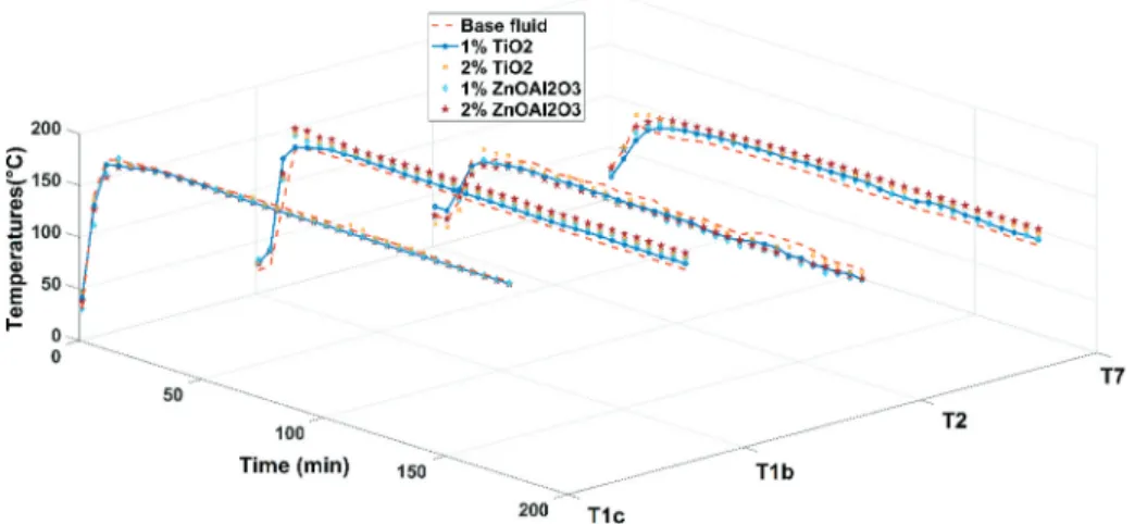
In this section, experimental results of the DAR system are discussed. These results indicate the temperatures of measured points and differences between of measured points in five different solu-tions. Figure 7 shows the change of the generator inlet temperatures of solutions (T7). The T7
generator inlet temperature is important for minimizing energy consumption at the generator. It should also be noted that the rich solution coming from the SHX into the generator needs to be almost at its saturated temperature. In this case, ammonia can be evaporated immediately. Otherwise, it takes time to evaporate and less ammonia vapor is produced by the generator [48]. As seen in Figure 7, temperature values of solution increase rapidly and after 40 min they became stable. Also, Figure 7
clearly demonstrates that adding nanoparticles and surface active agent to the base fluid make a significant difference in terms of the generator inlet temperatures (T7). In the experiments, the T7
temperatures of base fluid (ammonia-water of 25%) only reach up to 87°C. However, the T7
Figure 7. Graph of the measured T1b, T1c, T2, and T7 versus time for the different fluids.
temperatures of nanofluids (1% TiO2, 2% TiO2,1% ZnOAl2O3 and 2% ZnOAl2O3 solutions) reach
higher values than the base fluid with the range of 94°C-101°C. The use of nanoparticles in the base fluid helps evaporate the refrigerant and also protects the system from the temperature shifting effect [49].
Regard in Figure 7, comparing the nanoparticle types, the T7generator inlet temperatures of
nanofluid containing 1% TiO2 nanoparticles have no meaningful difference with those of nanofluid
containing 1% ZnOAl2O3 nanoparticles at the end of 180 min. Although, the difference becomes
visible in comparing nanofluids containing 2% ZnOAl2O3 and 2% TiO2 nanoparticles. The T7
generator inlet temperature of nanofluid containing 2% ZnOAl2O3 nanoparticles is the highest
temperature value according to others, and the T7 temperature of nanofluid containing 2% TiO2
nanoparticles are nearly 4.2°C lower than the highest value at the end of 180 min. Moreover, the difference between T7 generator inlet temperatures of the base fluid and the highest value fluid (2%
ZnOAl2O3 nanofluid) is about 14°C. The obtained results show that the addition of ZnOAl2O3
nanoparticles or TiO2 nanoparticles to the base fluid led to absorb more heat energy. Moreover,
more heat absorption facilitates the separation of water vapor in ammonia vapor at the rectifier part of the system. It should be noted that the addition of hybrid nanoparticles gives better results in comparing with single nanoparticles in most cases. Also the increase in the generator heat transfer rate results in an increased vapor generation [50].
The generator temperature changes of the weak solution values (T1b) over time for different
working fluids are shown in Figure 7. During the measurements, small changes in the T1b temperature
occur; however, these are assumed as acceptable. These fluctuations are particularly so apparent in T1b
values of nanofluid containing 2% TiO2 nanoparticles and theT1bvalues of base fluid (see Figure 7).
Moreover, T1bvalues of nanofluid containing ZnOAl2O3 nanoparticles are more stable and showed
nearly the same behavior in the graphic. After 140 min. in the measurements, all temperature curves become very close to each other. Regarding to obtained results, it can easily be said that same amount of energy is absorbed in five different solutions.
In Figure 7, another result of the study is in the temperature differences of T1c values for five various
solutions. As can be seen in Figure 7, there are extra heat energies seen in nanofluids. It is clear that using nanoparticles and surface active agent in the solutions generate extra heat energy and it is taken from generator part. In addition to this, hybrid nanoparticles receive more heat energy than single nanoparticles. This result also shows similarities with the literature as seen later. Jiang et al. [25] found that the use of TiO2 nanoparticles lead an increase in the generator temperatures of the system by
comparing the nanoparticle-free system. In addition, a theoretical study conducted by Micallef and
Micallef [51] expressed that increasing generator temperature heightens the performance of the system.
The variation of the condenser inlet temperature (T2) for five different solutions over time is given
in Figure 7. It is clearly known from the literature that high condenser temperatures lead low COP in DAR system [19, 52]. Thus, the lower T2 values lead higher COP values in the DAR system. It is clearly
seen in Figure 7 that T2 temperatures in the base fluid fluctuates significantly compared to other
nanofluids. Therefore, it should be indicated that nanofluids display more stable behavior in terms of the condenser inlet temperatures.
The variation of condenser outlet temperature (T3) with respect to over time for five fluids tested is
presented in Figure 8. It can be clearly found from the literature that higher condenser temperatures lead low COP in DAR system [19, 52, 53]. Thus, low T3 values lead higher COP values in the DAR
system. The outlet temperature of condenser (T3) decreases slightly with the use of nanofluid as
a working fluid. The drop values of T3 for 1% TiO2, 2% TiO2, 1% ZnOAl2O3, and 2% ZnOAl2O3 are,
respectively, approximately 2°C, 4°C, 9°C, and 10°C in the nanofluid concentrations compare to the base fluid, respectively. Adding nanosized metallic particles to the working fluids enhance the thermal conductivity of the base fluid, since the thermal conductivity of metals are higher than that of the base fluid. Moreover, there is no optimum values for evaporator temperature as well.
The evaporator output temperatures of the base fluid and the nanofluids (T5) are shown in Figure 8.
High evaporator temperature provides better performance in DAR system [53]. In other words, increased nanoparticle concentration in the ammonia solution rises cooling capacity of the DAR system. It can be seen in Figure 8 that the addition of nanoparticles ensures the temperature drop in the evaporator in a shorter time interval. Consequently, energy saving can be achieved.
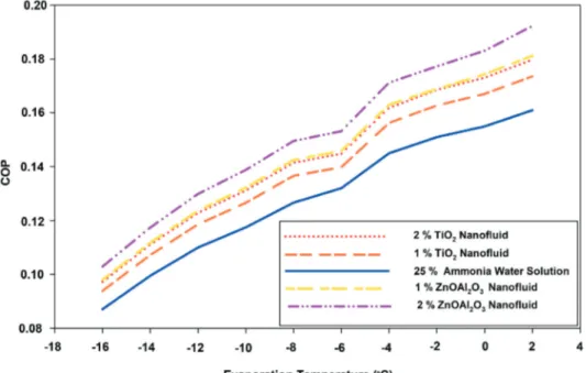
Figure 9 shows change of the COP with respect to time for the different working fluids. It can be seen from Figure 9 that the COP changes at different evaporation temperatures ranged from −16°C to 2°C. As the Figure 9 illustrates that COP decreases notably when the evaporation temperature diminishes. However, the hybrid nanofluids (ZnOAl2O3 nanoparticles with base fluid) as a working
fluid still have higher COP in comparison to other working fluids. Jiang et al. [25] also found the
Figure 9. Change of the COP versus time for the different working fluids.
similar relation between decreasing evaporation temperatures and COP for TiO2 nanoparticles in
a DAR system.
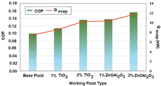
In Figure 10, COP and Qevap values with respect to working fluid types is given. It shows the
COP values of different working fluids after 120 second when the systems reached to steady-state condition. In the literature, Pérez-García et al. [14] investigated COP value in a small DAR by changing the thermostat positions. The highest COP value obtained was 0.1492, which was very close to the results of this study. As it can be seen, COP values improved by using nanofluids and increasing nanoparticle concentration also lead to more increment in COP. This increament ratios are 14%, 37%, 38%, and 56% respectively. The biggest disadvantage of the DAR systems is the low performance as mentioned above. In this regard, nanofluids with their superior thermal properties can be used increase the performance of absorption cooling systems. Moreover, Qevap
values of the system changes with different nanofluids. It is clearly seen that Qevap values also
rise related to working fluid types.
Figure 10. Graph of the COP and Qevap values for the different working fluid types.
Modeling results
In this section, the simulation results of the study are verified and compared with the experimental results to provide detailed information about optimum working conditions. Initial values of various sections (e.g., generator, condenser, absorber, evaporator) are taken into account to realize the simulation. With these initial parameters, the thermodynamic properties of the nanofluids are also calculated by utilizing nanofluid equations in each of the components. Moreover, these results are incorporated to the model as part of the simulation.
In order to compare the results of the experiments and simulations, the change of COP values for the base fluid and the different nanofluids in the DAR system is plotted in Figure 11. As can be seen in Figure 11, the COP values of the simulated system for various nanofluids show a similar trend to experimental results. The use of hybrid nanofluids (1% ZnOAl2O3 and 2%
ZnOAl2O3) gives better results in both experimental and simulation results. Regarding to the
Figure 12. Graph of the COP and Qevap values with respect to driving steam flow rates from generator for the different working fluid
types.
Figure 13. Graph of the COP and Qevap values with respect to outlet temperature of generator for the different working fluid types.
Figure 11, there are slightly higher COP values indicated in simulation results; however, the difference between the experimental and simulation results ranges from 1% to 5% caused by increasing nanoparticle ratios in the solution.
Figure 12 shows a graph of the COP and Qevap values with respect to driving steam flow rates from generator for different working fluids. It demonstrates the COP values of different working fluids after 120 second when the systems reached to steady-state condition.As it can be seen, COP values improved by using nanofluids and increasing nanoparticle concentration also lead to more increment in COP. Moreover, Qevap values of the system changes with different
nanofluids. It is clearly seen that Qevap values also rise related to working fluid types. In Figure
12 also demonstrates that the mass flowrate of ammonia vapor is increased with utilization of hybrid nanofluid as a working fluid.
Figure 13 illustrates a graph of the COP and Qevap values with respect to outlet temperature of generator for different working fluids. The outlet temperature of generator has risen notably by usage of nanofluid. Maximum temperature values are seen in 2% TiO2 nanofluid and 2% ZnOAl2O3
nanofluid. The obtained results also promote that the addition of ZnOAl2O3nanoparticles or TiO2
nanoparticles to the base fluid lead to absorb more heat energy. Thus, more heat increases the outlet temperatures of generator for different nanofluids.
Conclusion
In this work, the use of various nanoparticles (ZnOAl2O3 and TiO2) with different ratios was
investigated experimentally and theoretical modeling in the MATLAB/Simulink toolbox environ-ment. It was obtained that the COP values of the DAR systems significantly increased by using nanoparticles. Moreover, hybrid nanoparticles increased performance better than single nanoparti-cles. In terms of the COP values, the DAR system using nanofluid with 2% ZnOAl2O3 shows almost
57% better performance than the base fluid. Also, the use of nanofluid contains 2% nanoparticle concentrations exhibited better performance than nanofluid contains 1% nanoparticle. COP values of the nanofluid with 2% ZnOAl2O3 nanoparticles shows 13% better than the 1% one. The nanofluid
contains 2% TiO2nanoparticlesdemonstrates 19% better performance than the nanofluid contains
1% TiO2 nanoparticles. The process description of the DAR has been presented and modeling code
has been performed as well in the MATLAB/Simulink toolbox environment. The difference between COP values of experimental results and simulation results ranges from 1%-5%. As a result of simulation results, the outlet temperature of generator has risen notably by usage of nanofluid. Maximum temperature values are seen in 2% TiO2 nanofluid and 2% ZnOAl2O3 nanofluid. The
obtained results also promote that the addition of ZnOAl2O3 nanoparticles or TiO2 nanoparticles to
the base fluid lead to absorb more heat energy. Consequently, the utilization of nanofluid in the DAR system leads to an enhance in energy saving, and at the same time indicates a more stable working condition.
Nomenclature
Roman
A total area, m2
cp specific heat capacity, kJ kg−1K−1
COP coefficient of performance, dimensionless
f circulation ratio
h specific enthalpy, kJkg−1
k thermal conductivity, W m−1K−1
L length of the tube, m
_
m mass flow rate, kgs−1
N number of the fins
Roman
A total area, m2
cp specific heat capacity, kJ kg−1K−1
COP coefficient of performance, dimensionless
f circulation ratio
h specific enthalpy, kJkg−1
k thermal conductivity, W m−1K−1
L length of the tube, m
_
m mass flow rate, kgs−1
N number of the fins
Nu Nusselt number, dimensionless
_Q power, kW
s separation distance between fins, m
T temperature, °C or °K
U overall heat loss, kW m−2K−1
x mass fraction, %
X concentration percentage, %
Greek
α heat transfer coefficient, Wm−2K−1
η effectiveness of fin, %
ε effectiveness of heat exchanger, %
� volume fraction, %
ρ density, kg m−3
μ dynamic viscosity, Pa s
Subscripts
abs absorber
abs hex from absorber to heat exchanger stream
evap abs from evaporator to absorber stream
hex abs from heat exchanger to absorber stream
bf base fluid
cond condenser
evap evaporator
fin finned condenser
gen generator h heater He helium np nanoparticle nf nanofluid r refrigerant rf rectifier
shx solution heat exchanger
str rich solution
unfin unfinned condenser
wk weak solution
hex heat exchanger
Research highlight
● Experimental an numerical study on effect of nanofluid usage on DAR system. ● Thermodynamic performance of DAR is comparied for mixed various nanofluids.
● These occured from 25% ammonia/water couple with different rates of added ZnOAl2O3 and TiO2 nanoparticles. ● The DAR system with 2% ZnOAl2O3 showed better performance than the system with 1% one.
● The system with 2% ZnOAl2O3 led to 57% % increment in COP.
ORCID
Adnan Sözen http://orcid.org/0000-0002-8373-2674 Engin Özbaş http://orcid.org/0000-0003-4922-7890
References
[1] “The future of cooling: opportunities for energy-efficient air conditioning”, Inter. Energy Agency., 2018. [2] M. Santamouris, “Cooling the buildings-past, present and future,” Energy Build., vol. 128, pp. 617–638, 2016.
DOI: 10.1016/j.enbuild.2016.07.034.
[3] E. Masanet et al., “Energy technology perspectives 2016 – towards sustainable urban energy systems,” Inter. Energy Agency., 2016.
[4] M. Herrando, A. M. Pantaleo, K. Wang, and C. N. Markides, “Solar combined cooling, heating and power systems based on hybrid PVT, PV or solar-thermal collectors for building applications,” Renewable Energy., vol. 143, pp. 637–647, 2019. DOI: 10.1016/j.renene.2019.05.004.
[5] K. E. Herold, R. Radermacher, and S. A. Klein, “Absorption chillers and heat pumps,” CRC Press, 2016. [6] X. Shuxue and M. Guoyuan, “Exergy analysis for quasi two-stage compression heat pump system coupled with
ejector,” Exp. Therm Fluid Sci., vol. 35, pp. 700–705, 2011. DOI: 10.1016/j.expthermflusci.2011.01.004. [7] M. Elakdhar, E. Nehdi, and L. Kairouani, “Analysis of a compression/ejection cycle for domestic refrigeration,”
Ind. Eng. Chem. Res., vol. 46, pp. 4639–4644, 2007. DOI: 10.1021/ie070377e.
[8] J. Sarkar, “Ejector enhanced vapor compression refrigeration and heat pump systems-A review,” Renewable Sustainable Energy Rev., vol. 16, pp. 6647–6659, 2012.
[9] A. Sözen, T. Menlik, and E. Özbaş, “The effect of ejector on the performance of diffusion absorption refrigeration systems: an experimental study,”,” Appl. Therm. Eng., vol. 33, pp. 44–53, 2012. DOI: 10.1016/j. applthermaleng.2011.09.009.
[10] S. Anand, A. Gupta, and S. K. Tyagi, “Simulation studies of refrigeration cycles: a review,”,” Renewable Sustainable Energy Rev., vol. 17, pp. 260–277, 2013. DOI: 10.1016/j.rser.2012.09.021.
[11] R. Sirwan, M. A. Alghoul, K. Sopian, Y. Ali, and J. Abdulateef, “Evaluation of adding flash tank to solar combined ejector–absorption refrigeration system,” Solar Energy., vol. 91, pp. 283–296, 2013.
[12] A. M. Abed, M. A. Alghoul, M. H. Yazdi, A. N. Al-Shamani, and K. Sopian, “The role of enhancement techniques on heat and mass transfer characteristics of shell and tube spray evaporator: a detailed review,” Appl. Therm. Eng., vol. 75, pp. 923–940, 2015. DOI: 10.1016/j.applthermaleng.2014.10.020.
[13] J. Sarkar, P. Ghosh, and A. Adil, “A review on hybrid nanofluids: recent research, development and applications,” Renew. Sust. Energy Rev., vol. 43, pp. 164–177, 2015. DOI: 10.1016/j.rser.2014.11.023.
[14] V. Pérez-García, J. L. Rodríguez-Muñoz, J. M. Belman-Flores, C. Rubio-Maya, and J. J. Ramírez-Minguela, “Theoretical modeling and experimental validation of a small capacity diffusion-absorption refrigerator,” Int. J. Refrig., vol. 104, pp. 302–310, 2019. DOI: 10.1016/j.ijrefrig.2019.05.014.
[15] F. D. Chaves, M. F. S. Moreira, R. N. Koury, L. Machado, and M. F. B. Cortez, “Experimental study and modeling within validation of a diffusion absorption refrigerator,” Int. J. Refrig., vol. 101, pp. 136–147, 2019. DOI: 10.1016/ j.ijrefrig.2019.01.019.
[16] J. Chen, J. K. Kim, and K. E. Herold, “Performance enhancement of a diffusion absorption refrigerator,”,” Int. J. Refrig., vol. 19, pp. 208–218, 1996. DOI: 10.1016/0140-7007(96)87215-X.
[17] A. Zohar, M. Jelinek, A. Levy, and I. Borde, “The influence of the generator and bubble pump configuration on the performance of diffusion absorption refrigeration (DAR) system,” Int. J. Refrig., vol. 31, pp. 962–969, 2008. DOI: 10.1016/j.ijrefrig.2008.01.009.
[18] A. Zohar, M. Jelinek, A. Levy, and I. Borde, “The influence of diffusion absorption refrigeration cycle config-uration on the performance,” Appl. Therm. Eng., vol. 27, pp. 2213–2219, 2007. DOI: 10.1016/j. applthermaleng.2005.07.025.
[19] G. Starace and L. De Pascalis, “An enhanced model for the design of Diffusion Absorption Refrigerators,” Int. J. Refrig., vol. 36, pp. 1495–1503, 2013. DOI: 10.1016/j.ijrefrig.2013.02.016.
[20] J. M. Belman-Flores, J. L. Rodríguez-Muñoz, C. Rubio-Maya, J. J. Ramírez-Minguela, and V. Pérez-García, “Energetic analysis of a diffusion–absorption system: a bubble pump under geometrical and operational condi-tions effects,” Appl. Therm. Eng., vol. 71, pp. 1–10, 2014.
[21] A. Sözen, et al., “Improving the thermal performance of diffusion absorption refrigeration system with alumina nanofluids: an experimental study,” Int. J. Refrig., vol. 44, pp. 73–80, 2014. DOI: 10.1016/j.ijrefrig.2014.04.018. [22] L. Yang, K. Du, S. Bao, and Y. Wu, “Investigations of selection of nanofluid applied to the ammonia absorption
refrigeration system,” Int. J. Refrig., vol. 35, no. 8, pp.2248–2260, 2012. DOI: 10.1016/j.ijrefrig.2012.08.003. [23] W. Wu, J. Wu, Y. Wang, and H. Zhang, “The enhancing influence of nanoparticles on ammonia/water falling film
absorption in binary nanofluids under pressure reducing conditions,” J. Therm. Sci. Technol., vol. 12, no. 2, 2017. DOI: 10.1299/jtst.2017jtst0018.
[24] M. Aramesh, F. Pourfayaz, M. Haghir, A. Kasaeian, and M. H. Ahmadi, “Investigating the effect of using nanofluids on the performance of a double-effect absorption refrigeration cycle combined with a solar collector,” Proc. Inst. Mech. Eng. Part A., 2019. DOI: 10.1177/0957650919889811.
[25] W. Jiang, S. Li, L. Yang, and K. Du, “Experimental investigation on performance of ammonia absorption refrigeration system with TiO2 nanofluid,” Int. J. Refrig., vol. 98, pp. 80–88, 2019. DOI: 10.1016/j. ijrefrig.2018.09.032.
[26] L. Yang, W. Jiang, X. Chen, and K. Du, “Dynamic characteristics of an environment-friendly refrigerant: ammonia–water based TiO2 nanofluid,” Int. J. Refrig., vol. 82, pp. 366–380, 2017. DOI: 10.1016/j. ijrefrig.2017.06.006.
[27] A. Khanlari, A. Sözen, and H. İ. Variyenli, “Simulation and experimental analysis of heat transfer characteristics in the plate type heat exchangers using TiO2/water nanofluid,” Int. J. Numer. Methods Heat Fluid Flow., vol. 29, pp. 1343–1362, 2019a. DOI: 10.1108/HFF-05-2018-0191.
[28] S. S. Sanukrishna, M. Murukan, and M. J. Prakash, “An overview of experimental studies on nanorefrigerants: recent research, development and applications,” Int. J. Refrig., pp. 552–577, 2018.
[29] A. Khanlari, A. Sözen, H. İ. Variyenli, and M. Gürü, “Comparison between heat transfer characteristics of TiO2/ deionized water and kaolin/deionized water nanofluids in the plate heat exchanger,” Heat Transfer Res., vol. 50, pp. 435–450, 2019b. DOI: 10.1615/HeatTransRes.2018026288.
[30] A. Zohar, M. Jelinek, A. Levy, and I. Borde, “Performance of diffusion absorption refrigeration cycle with organic working fluids,” Int. J. Refrig., vol. 32, pp. 1241–1246, 2009. DOI: 10.1016/j.ijrefrig.2009.01.010.
[31] L. Yang, W. Ji, M. Mao, and J. Huang, “An updated review on the properties, fabrication and application of hybrid-nanofluids along with their environmental effects,” J. Clean. Prod., vol. 257, pp. 120408, 2020a. DOI: 10.1016/j.jclepro.2020.120408.
[32] M. Asadi, A. Asadi, and S. Aberoumand, “An experimental and theoretical investigation on the effects of adding hybrid nanoparticles on heat transfer efficiency and pumping power of an oil-based nanofluid as a coolant fluid,” Int. J. Refrig., vol. 89, pp. 83–92, 2018. DOI: 10.1016/j.ijrefrig.2018.03.014.
[33] M. Siavashi, H. R. T. Bahrami, and E. Aminian, “Optimization of heat transfer enhancement and pumping power of a heat exchanger tube using nanofluid with gradient a multi-layered porous foams,” Appl. Therm. Eng., vol. 138, pp. 465–474, 2018. DOI: 10.1016/j.applthermaleng.2018.04.066.
[34] X. Wu, S. Xu, and M. Jiang, “Development of bubble absorption refrigeration technology: a review,” Renewable Sustainable Energy Rev., vol. 82, pp. 3468–3482, 2018. DOI: 10.1016/j.rser.2017.10.109.
[35] M. A. Ersöz, “Investigation the effects of different heat inputs supplied to the generator on the energy performance in diffusion absorption refrigeration systems,” Int. J. Refrig., vol. 54, pp. 10–21, 2015. DOI: 10.1016/j.ijrefrig.2015.02.013.
[36] S. U. Choi and J. A. Eastman, Enhancing thermal conductivity of fluids with nanoparticles Argonne National Lab., IL (United States, 1995.
[37] W. Yu, D. M. France, J. L. Routbort, and S. U. Choi, “Review and comparison of nanofluid thermal conductivity and heat transfer enhancements,” Heat Tran. Eng., vol. 29, no. 5, pp.432–460, 2008. DOI: 10.1080/ 01457630701850851.
[38] B. Mehrvarz, F. Bahadori, and S. Zolfaghari Moghaddam, “Heat transfer enhancement in distribution transfor-mers using TiO2 nanoparticles,” Adv. Powder Technol., vol. 30, pp. 221–226, 2019. DOI: 10.1016/j. apt.2018.10.026.
[39] D. Cabaleiro, et al., “Thermal conductivity of dry anatase and rutile nano-powders and ethylene and propylene glycol-based TiO2 nanofluids,” J. Chem. Thermodyn., vol. 83, pp. 67–76, 2015. DOI: 10.1016/j.jct.2014.12.001. [40] S. Mukherjee, S. Chakrabarty, P. C. Mishra, and P. Chaudhuri, “Transient heat transfer characteristics and
process intensification withAl2O3-water and TiO2-water nanofluids: an experimental investigation,” Chem. Eng.
Process., vol. 150, pp. 107887, 2020. DOI: 10.1016/j.cep.2020.107887.
[41] A. Khanlari, D. Yılmaz Aydın, A. Sözen, M. Gürü, and H. İ. Variyenli, “Investigation of the influences of kaolin-deionized water nanofluid on the thermal behavior of concentric type heat exchanger,” Heat Mass Transfer., 2020. DOI: 10.1007/s00231-019-02764-1.
[42] S. J. Kline and F. A. McClintock, “Describing uncertainties in single-sample experiments,” Mech. Eng., vol. 75, pp. 3–8, 1953.
[43] S. Bittanti, S. A. De Marco, M. Giannatempo, and V. Prandoni, “A dynamic model of an absorption chiller for air conditioning,” Renewable Energy and Power Quality Journal., 2010. DOI: 10.24084/repqj08.428.
[44] M. Conde, “Theoretical analysis of NH3-H2O refrigeration system coupled with diesel engine: a thermodynamic study,” Zurich, 2004.
[45] C. E. Vanderzee and D. L. King, “The enthalpies of solution and formation of ammonia,” J. Chem. Thermodyn., vol. 4, no. 5, pp.675–683, 1972. DOI: 10.1016/0021-9614(72)90039-0.
[46] N. Shankar Ganesh and T. Srinivas, “Evaluation of thermodynamic properties of ammonia water mixture up to 100 bar for power application system,” J. Mech. Eng. Res., vol. 3, pp. 25–39, 2011.
[47] L. Yang, et al., “A review of heating/cooling processes using nanomaterials suspended in refrigerants and lubricants,” Int. J. Heat Mass Trans., vol. 153, pp. 119611, 2020b. DOI: 10.1016/j.ijheatmasstransfer.2020.119611. [48] D. W. Sun, I. W. Eames, and S. Aphornratana, “Evaluation of a novel combined ejector-absorption refrigeration
Cycle-I: computer simulation,” Int. J. Refrig., vol. 19, pp. 172–180, 1996. DOI: 10.1016/0140-7007(96)00010-2. [49] J. Fernández-Seara and J. Sieres, “Ammonia–water absorption refrigeration systems with flooded evaporators,”
Appl. Therm. Eng., vol. 26, pp. 2236–2246, 2006. DOI: 10.1016/j.applthermaleng.2006.03.011.
[50] M. I. S. Adjibade, A. Thiam, C. Awanto, B. A. Ndiogou, and V. Sambou, “Dynamic investigation of the diffusion absorption refrigeration system NH3-H2O-H2,” Case Stud. Therm. Eng., vol. 10, pp. 468–474, 2017. DOI: 10.1016/ j.csite.2017.10.006.
[51] D. Micallef and C. Micallef, “Mathematical model of a vapor absorption refrigeration unit,” Int. J. Simul. Model., vol. 9, pp. 86–97, 2010. DOI: 10.2507/IJSIMM09(2)3.153.
[52] A. Zohar, M. Jelinek, A. Levy, and I. Borde, “Numerical investigation of a diffusion absorption refrigerator cycle,” Int. J. Refrig., vol. 28, pp. 515–525, 2005. DOI: 10.1016/j.ijrefrig.2004.11.003.
[53] D. W. Sun, “Computer simulation and optimization of ammonia-water absorption refrigeration systems,” Energy Sources., vol. 19, no. 7, pp.677–690, 1997. DOI: 10.1080/00908319708908882.
![Figure 5. A DAR cycle (adapted from Zohar et al. [ 18 ]).](https://thumb-eu.123doks.com/thumbv2/9libnet/3817155.33545/10.756.202.548.79.751/figure-a-dar-cycle-adapted-from-zohar-al.webp)