Tar. Bil. Der.
Dergi web sayfası: www.agri.ankara.edu.tr/dergi
Journal homepage: www.agri.ankara.edu.tr/journal
Effects of Drip Irrigation System Pressure Fluctuations on Drip
Lateral Emitter Flow Rate and Diameter Change
Ergün DOĞAN
Harran University, Faculty of Agriculture, Department of Agricultural Structure and Irrigation, 63040 Şanlıurfa, TURKEY
ARTICLE INFO
Research Article Agricultural Technologies
Corresponding author: Ergün DOĞAN, e-mail: [email protected], Tel: +90(414) 344 00 72/3758 Received: 07 October 2010, Received in revised form: 24 January 2011, Accepted: 01 February 2011
ABSTRACT
This study was conducted to determine the effects of drip irrigation system in line pressure fluctuations on drip lateral diameter expansion and emitter discharge rates. Pressure tests were carried out using ASAE test procedures with 6 different laterals with different physical characteristics from different manufacturers. Measurements were conducted using 3 replications of all laterals. Results showed that significant (P<0.05) swelling of drip irrigation laterals occurred due to pressure increases. However, there was no clear indication of drip lateral wall thickness effect on measurements swelling measurements. Results also indicated that changes in diameter at the maximum applied pressure ranged from 2 to 4%. Irrigation system pressure increases resulted in increased drip lateral emitter flow rates at statistically significant level (P<0.05) for all 6 brands used in this study.
Keywords: Pressure increase; Discharge; Lateral diameter; Wall thickness; Efficiency
Damla Sulama Sistemlerinde Basınç Değişimlerinin Damlatıcı
Debisi ve Lateral Çapı Değişimine Etkisi
ESER BĐLGĐSĐ
Araştırma Makalesi Tarım Teknolojileri
Sorumlu Yazar: Ergün DOĞAN, e-posta: [email protected], Tel: +90(414) 344 00 72/3758 Geliş tarihi: 07 Ekim 2010, Düzeltmelerin gelişi: 24 Ocak 2011, Kabul: 01 Şubat 2011
ÖZET
Bu çalışmada, damla sulama sistemlerinde meydana gelen basınç artışının damlatıcı debisi ile lateral çapına etkisi araştırılmıştır. Çalışmada, ASAE standardına göre test protokolleri oluşturulmuş, 6 farklı üretici firma tarafından üretilen damla sulama lateralleri kullanmış ve yapılan ölçümler 3 tekrarlı olarak gerçekleştirilmiştir. Deneme sonuçlarına göre; (a) üretici firmalar tarafından önerilen işletme basınçlarına ek olarak 25 kPa artırımlı 100.0 kPa’a kadar olan basınç değişimlerinde lateral çaplarında istatistiksel olarak önemli genişlemeler meydana gelebileceğini göstermiştir (P<0.05). Ancak farklı firmalar tarafından üretilen farklı et kalınlığındaki laterallerin etkisi saptanamamıştır. Ayrıca, uygulanan maksimum basınç artışları sonucunda lateral çaplarında % 2 ile 4 lük artışlar saptanmıştır. Diğer taraftan (b), sulama sisteminde meydana gelebilecek basınç artışlarının test edilen tüm 6 damlatıcı debilerinde önemli düzeyde (P<0.05) artışlar sağladığı hesaplanmıştır.
T
A
R
IM
B
İL
İM
LE
R
İ
D
E
R
G
İS
İ
J
O
U
R
N
A
L
O
F
A
G
R
IC
U
LT
U
R
A
L
S
C
IE
N
C
E
S
16 ( 20 10 ) 23 5-24 1
1. Introduction
With new developments in agricultural, industrial and municipal industries, need of fresh water sources are increasing. Additionally, environmental concerns elevate competition for fresh water resources resulting in need for more efficient irrigation systems compared to traditional surface irrigation systems (Phene et al 1992). Compared to surface and sprinkler irrigation systems, drip irrigation systems have some advantages (Phene et al 1992; Bucks et al 1981; Lamm et al 1992; Dhuyvetter et al 1995) such as: (a) effective and efficient application of irrigation water to the crop root zone; (b) injection of chemicals and fertilizers through irrigation system (Bucks et al 1981); (c) adaptation to use in different topography (Lamm et al 1992; Dhuyandtter et al 1995; Wei et al 2003) and; (d) less risk of plant disease due to wetting of plant canopy. Karaca & Selenay (2001) reported that drip irrigation system used about 40% less irrigation water as compared to surface irrigation and also drip irrigation was economically favorable at/above 13 ha agricultural land under Harran Plain conditions. Similar results in favor of drip irrigation system were also reported Soydam & Cakmak (2006).
For an efficient irrigation, water has to be uniformly applied to the crop field. The emitter device is the main component of a drip irrigation lateral and determines the drip irrigation capacity. In order to have limited emitter discharge fluctuations, emitter exponent (x) has to be as low as possible (Yun-Kai et al 2006). Factors effecting uniformity are; changes in manufacturing process, change in system pressure, topography, clogging of emitters, and friction losses trough laterals (Solomon 1985; Mizyed & Kruse 1989). Mizyed & Kruse (1989) claimed that water application efficiency of drip irrigation systems is altered by system - emitter hydraulics, and system operation. Long drip lateral lengths in the large agricultural fields could also be a source of non-uniformity. Therefore, it is important to know the uniformity characteristics of drip irrigation laterals before they are applied to agricultural fields. Non-uniform irrigation results in less crop development and yield due to over and/or deficit irrigation at the top and
end of a given field (Wu 1997; Bhatnagar & Srivastava 2003). Uniform water application through drip irrigation systems could even be more important with fertilizer and chemical applications. However, the negative effect of non-uniform irrigations could be avoided with appropriately planned drip irrigation system (Decroix & Malaval 1985). Therefore, emitters play a crucial role on system performance (Al-Amound 1995).
Hence, the goal of this study was to evaluate the drip irrigation system pressure fluctuations on dripline’ diameter expansion and emitter flow rates for 6 different products.
2. Material and Methods
This study was conducted at the department of Irrigation Engineering hydraulic laboratory, Faculty of Agriculture, Harran University, Turkey. 6 commonly used non-pressure compensating drip irrigation laterals from different manufacturers were tested with 3 replications. Tested drip irrigation laterals’ wall thickness ranged from 0.85 - 1.10 mm with all having 16 mm diameter. Emitter spacing ranged from 250 mm to 750 mm with all emitters having a discharge rate of 4 l h-1 (Table 1). Drip laterals were cut at a length containing 5 emitters with three replications and connected to a manifold that was attached to an electrical water pump. Irrigation water used in the study was municipal tap water at a temperature around 25°C. Before measurements were taken, system was operated for 15 minutes to condition the laterals. During the tests, some of the water was also allowed to discharge in order to insure a constant pressure and simulate field conditions (Figure 1). After 15 minutes of conditioning, emitter flow rate measurements were carried out by measuring discharges from all 5 emitters on a single lateral length. Laterals were first tested at manufacturer suggested pressure (MSP) and then the same laterals were tested with pressure increments of 25 kPa up to a pressure increase of 100 kPa.
Drip irrigation laterals were elevated about 50 cm above the ground so that flow rate measurement could easily be carried out. Flow rates were collected with water collectors for 60 seconds and then weighed with an electronic balance with a 0.01
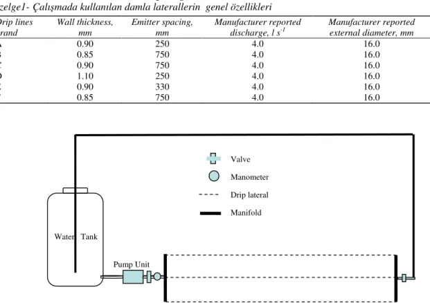
Table 1-General characteristics of drip irrigation laterals Çizelge1-Çalışmada kullanılan damla laterallerin genel özellikleri
Drip lines brand Wall thickness, mm Emitter spacing, mm Manufacturer reported discharge, l s-1 Manufacturer reported external diameter, mm A 0.90 250 4.0 16.0 B 0.85 750 4.0 16.0 C 0.90 750 4.0 16.0 D 1.10 250 4.0 16.0 E 0.90 330 4.0 16.0 F 0.85 750 4.0 16.0
Figure 1-System set up used to test drip emitters Şekil 1-Damla laterallerinin testinde kullanılan sistem g sensitivity and measurements were converted to l s-1 unit. The water collectors used to catch the emitter discharge were dried after each measurement. The test data were analyzed with a regression analyses method in order to determine the emitter coefficients and exponents for all tested brands’ laterals as given below (ASAE 2003):
X H K
q = × (1)
where: Q is discharge in l s-1; K is emitter coefficient; H is system operating pressure in kPa; and x is emitter exponent.
Drip lateral diameter changes due to pressure increases were measured between first and second emitter at all pressures once at a water temperature of 25°C with a digital caliper with 0.1 mm sensitivity. Diameter changes were measured at the same pressure and temperature on 3 drip lines.
Both emitter discharge results and lateral
swelling data were analyzed using both ANOVA and regression analysis methods in order to determine if there was any difference among treatments and also to calculate equations representing the measured parameters. Also, the degree of significance for all tested laterals determined using the same statistical test procedures with SPSS (2002) computer based statistical program.
3. Results and Discussions
The emitter discharge rate measurements indicated that overall, drip emitter flow rates at manufacturer reported operating pressures were close to manufacturer reported emitter discharge rates. In general, the highest difference between measured and manufacturer reported values were close to 0.9 l s-1. However the first two brands reported discharge rates were quite close to measured ones Pump Unit Valve Manometer Drip lateral Manifold Water Tank
with 0.1 l s-1. With increase in irrigation system pressure, emitter flow rates also started to increase regardless of the brands. Flow rate changes due to pressure changes were no more than 21 and 32% for pressure increases of 25 and 50 kPa, respectively, and those pressure increases represent 25 and 50% of manufacturer suggested operating pressures.
In general, as system pressure increased, emitter discharge also increased regardless of brands. ANOVA analysis of the discharge rate measurements under different pressures indicated a significant (P<0.05) increasing trend. Overall, emitter discharge rate measurements indicated that the change in flow rates were parallel to pressure increase. ANOVA and regression analyses of the flow rate data indicated that all regression equations
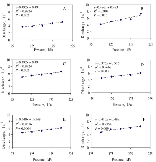
for all brands were significant (P<0.05) and indicated that the determined coefficients could be used for the emitters (Tables 2, 3 and Figure 2). On the other hand, 100% pressure increase resulted up to 50% discharge increase but overall was less than 40% for the tested laterals (Table 2). Similar to current study results, a strong relationship between drip irrigation system pressure and emitter flow rate was reported by researchers (Ozekici & Sneed 1995; Kirnak et al 2004; Clark et al 2005; Camoglu and Yavuz 2006). Regression analyses of the pressure tests results indicated that emitter flow rate equations (q = K×Hx) had emitter coefficients (K) of 0.45, 0.49, 0.49, 0.38, 0.34, and 0.41, whereas emitter exponent values were 0.45, 0.48, 0.49, 0.53, 0.55, and 0.50 for A, B, C, D, E, and F manufacturer laterals, respectively.
Table 2-Test results of drip irrigation laterals for lateral diameter to emitter discharge Çizelge 2-Damla lateralleri çap ve damlatıcı debi değişim sonuçları
Drip lines brand Lateral diameter swelling, % Min. flow rate, l s-1 Max. flow rate, l s-1 Flow rate increase, % Emitter coefficient, K Emitter exponent, x A 1.49 4.1 5.2 26.8 0.45 0.45 B 2.53 4.1 7.3 52.1 0.49 0.48 C 1.88 4.9 6.5 32.7 0.49 0.49 D 2.85 4.4 6.0 36.4 0.38 0.53 E 2.01 4.6 6.0 30.4 0.34 0.55 F 4.16 4.7 6.5 38.3 0.41 0.50
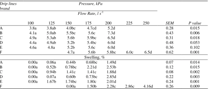
Table 3-Lateral diameter to emitter discharge changes at tested pressure and statistical analysis results Çizelge 3-Basınç artışlarına bağlı lateral çapı, damlatıcı debi değişimleri ve istatistik sonuçları
Drip lines brand Pressure, kPa Flow Rate, l s-1 100 125 150 175 200 225 250 SEM P value A 3.8a 3.8ab 4.0bc 4.7cd 5.2d 0.28 0.015 B 4.1a 5.0ab 5.5bc 5.6c 7.3d 0.43 0.006 C 4.9a 5.3ab 5.6b 5.9bc 6.5d 0.31 0.018 D 4.4a 4.9ab 5.2b 5.4bc 6.0d 0.48 0.053 E 4.6a 4.8a 5.2b 5.6c 6.0d 0.36 0.102 F 4.7a 5.6b 5.8bc 6.0c 6.5d 0.62 0.001 Swelling, % A 0.00a 0.06a 0.44b 0.68bc 1.49d 0.07 0.014 B 0.00a 0.52b 0.78bc 2.21d 2.53b 0.12 0.015 C 0.00a 0.94b 1.41c 1.41c 1.88d 0.08 0.002 D 0.00a 0.07a 0.60b 0.73bc 2.85d 0.22 0.003 E 0.00a 1.67b 1.74bc 1.80c 2.01d 0.24 0.001 F 0.00a 1.50b 2.28c 2.86c 4.16d 0.26 0.009
0 2 4 6 8 10 75 125 175 225 Pressure, kPa D is ch ar g e, l s -1 0 2 4 6 8 10 75 125 175 225 Pressure, kPa D is ch ar g e, l s -1 0 2 4 6 8 10 75 125 175 225 Pressure, kPa D is ch ar g e, l s -1 0 2 4 6 8 10 75 125 175 225 Pressure, kPa D is ch ar g e, l s -1 0 2 4 6 8 10 75 125 175 225 Pressure, kPa D is ch ar g e, l s -1 0 2 4 6 8 10 125 175 225 275 Pressure, kPa D is ch ar g e, l s -1
Figure 2-Relationship between system pressure and drip lateral diameter change of tested drip laterals manufactured by A, B, C, D, E, and F companies
Şekil 2-Çalışmada kullanılan A, B, C, D, E ve F firmalarına ait laterallerde basınç değişimlerine bağlı çap değişimleri
Even small changes in emitter exponents show that weakness of the emitter to pressure resulting in big variation in flow rate. Regression coefficients (R2
) for the equations were 0.93, 0.94, 0.98, 0.98, 0.96, and 0.98 for the respective laterals (Table 2). Since lower emitter exponents are indication of less susceptibility to pressure changes, emitters could be ranked as A, B, C, D, E, and F with an increasing trend. Similar results were also reported by Ozekici & Bozkurt (1996).
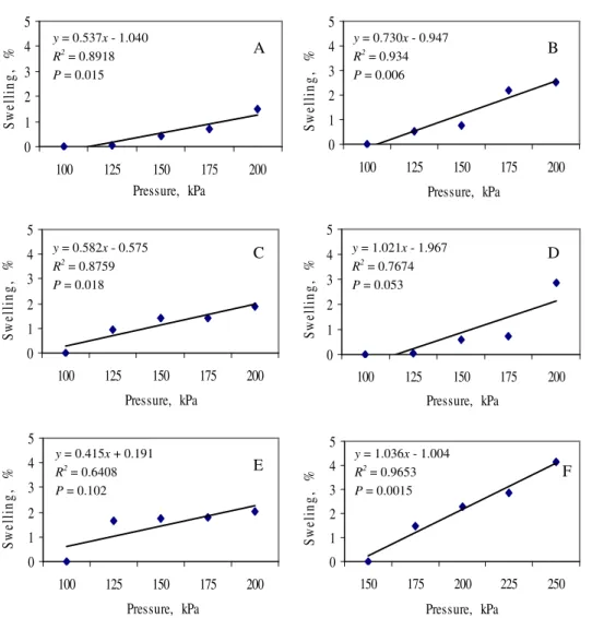
Drip irrigation lateral expansion ranged from 1.49 to 4.16% at maximum pressure increase
(100%). Generally, one might expect that wall thickness of a lateral play a role on diameter expansion, however there was no indication of that in our measurements (Table 3). The reason could be attributed to the pressures used in the study, which were not high enough to see the effect of the wall thickness on measurements. Up to 50 kPa (50%) pressure increase, lateral diameters were slightly affected and the effect was limited to 2% and most of the time was less than 1%. Swelling measurements in general indicated a significant (P<0.05) changes in lateral diameter in all
C D E F A y=0.486x + 0.483 B R2 = 0.904 P = 0.015 y=0.492x + 0.49 R2 = 0.9724 P = 0.002 y=0.375x + 0.526 R2 = 0.9662 P = 0.003 y=0.340x + 0.549 R2 = 0.9616 P = 0.0004 y=0.410x + 0.498 R2 = 0.9354 P = 0.009 y=0.492x + 0.491 R2 = 0.9724 P = 0.002
0 1 2 3 4 5 100 125 150 175 200 Pressure, kPa S w el li n g , % 0 1 2 3 4 5 100 125 150 175 200 Pressure, kPa S w el li n g , % 0 1 2 3 4 5 100 125 150 175 200 Pressure, kPa S w el li n g , % 0 1 2 3 4 5 100 125 150 175 200 Pressure, kPa S w el li n g , % 0 1 2 3 4 5 100 125 150 175 200 Pressure, kPa S w el li n g , % 0 1 2 3 4 5 150 175 200 225 250 Pressure, kPa S w el in g , %
Figure 3-Relationship between system pressure and drip lateral emitter flow rates of tested drip laterals manufactured by A, B, C, D, E, and F companies
Şekil 2-Çalışmada kullanılan A, B, C, D, E ve F firmalarına ait damlatıcılarda bacınç değişimleri ve debi değişim ilişkileri
diameters. However, with small pressure increases this significant difference was not obvious in all brands (Table 3 & Figure 3). Expansion of lateral diameters will certainly affect the hydraulic characteristics of drip line and possible interfering with overall performance of emitters.
4. Conclusions
In general, the effect of pressure increase resulted in increased swelling of the drip laterals and it was
statistically significant (P<0.05) for all tested materials. Lateral swellings for the maximum pressure did not exceed 5%. In general it was limited to 3%. Wall thickness of the laterals seemed not to be a factor affecting the swelling of the laterals. Significant diameter change (increase) could also reduce friction loss and affect emitter flow rates. An increase in irrigation system pressure resulted in increased emitter flow rates limited to 10%. However, the changes were even lesser in some of the brands compared to others.
A F E D C B y = 0.537x - 1.040 R2 = 0.8918 P = 0.015 y = 0.730x - 0.947 R2 = 0.934 P = 0.006 y = 0.582x - 0.575 R2 = 0.8759 P = 0.018 y = 1.021x - 1.967 R2 = 0.7674 P = 0.053 y = 0.415x + 0.191 R2 = 0.6408 P = 0.102 y = 1.036x - 1.004 R2 = 0.9653 P = 0.0015
Acknowledgement
This study was supported by TÜBĐTAK (project number 106 O 264) and I would like to thank TÜBĐTAK for the support and also I thank Mr. Mehmet Nur BAL for his help in this study.
References
Al-Amound A I (1995). Significance of energy losses due to emitter connections in trickle irrigation lines.
Journal of Agricultural Engineering Research 60
(1):1-5
ASAE (2003). ASABE standards engineering practices data, 43rd edition, MI, USA. p. 864
Bhatnagar P R & Srivastava R C (2003). Gravity-fed drip irrigation system for hilly terraces of the northwest Himalayas. Irrigation science 21:151-157
Bucks D A, Erie L J, French O F, Nakayama F S, & Pew W D (1981). Subsurface trickle irrigation management with multiple cropping. Transactions of
the ASAE 24:1482-1489
Camoglu G & Yavuz M Y (2006). Boruya içten geçik (in-line) ve dıştan geçik (on-line) damlatıcılarda yapım farklılığı katsayısının sulama yenesaklığına etkisi. Akdeniz Universitesi Ziraat Fakultesi Dergisi
19(1): 1-8
Clark G A, Lamm F L & Rogers D H (2005). Sensitivity of thin-walled drip tape emitter discharge to water temperature. Applied Engineering in Agriculture
21(5): 855-863
Decroix M & Malaval A (1985). Laboratory evaluation of trickle irrigation equipment for field system
design. In: Proceeding of third international
drip/trickle irrigation congress ASAE vol:1, pp. 325–
338, California, USA
Dhuyvetter K C, Lamm F R & Rogers D H (1995). Subsurface drip irrigation (SDI) for field corn - An economic analysis. In: Proceedings of the Fifth
International Microirrigation Congress, pp. 395-401,
April 2-6 1995, Orlando, FL
Ozekici B & Sneed R E (1995). Manufacturing variation for various trickle irrigation on-line emitter. Applied
Engineering in Agriculture 11(2): 235-240
Ozekici B & Bozkurt S (1996). Boru içi (in-line) damlatıcıların hirolik performanslarının belirlenmesi.
Turkish Journal of Agricultural Forestry 23(1): 19-24
Karaca G & Selenay M F (2001). Harran ovasında karık ve damla sulama sistemlerinin ekonomik yönden karşılaştırılması. Tarim Bilimleri Dergisi 7(1): 166-176
Kirnak H, Dogan E, Demir S & Yalcin S (2004). Determination of hydraulic performance of trickle irrigation emitters used in irrigation systems in Harran plain. Turkish Journal of Agricultural
Forestry 28: 223-230
Lamm F R, Stone L R & Manges H L (1992). Optimum lateral spacing for drip-irrigated corn. Written for presentation at the 1992 international winter meeting of ASAE. ASAE paper No. 92-2575. St. Joseph, MI. ASAE.
Mizyed N & Kruse E G (1989). Emitter discharge
evaluation of subsurface trickle irrigation.
Transactions of the ASAE 32(4):1223-1228
Phene C J, Yue R, Wo I-Pai, Ayers J E, Schoneman R A & Meso B (1992). Distribution uniformity of subsurface drip irrigation systems. Written for presentation at the1992 international winter meeting of ASAE. ASAE Paper no: 922569: 22 p. St. Joseph, MI. ASAE
Soloman K (1985). Global uniformity of trickle irrigation systems. Transactions of ASAE 28 (4). 1151-1158 Soydam A & Cakmak B (2006). Toplu basınclı sulama
sistemlerinin ekonomik yönden kaşılaştırılması; Yaylak projesi 1400 nolu yedeği örneği. Tarim
Bilimleri Dergisi 12(1): 74-78
SPSS Inc. (2002) SPSS Base 10.0 for Windows User's Guide. SPSS Inc., Chicago IL. SPSS Reliase 15.0 for Windows Statistical Software
Yun-Kai L, Pei-ling Y & Shu-mei R (2006). Hydraulic characterizations of tortuous flow in path drip irrigation emitter. Jurnal of Hydrodynamics 18(4): 449-457
Wei Z, Tang Y, Zhao W & Lu B (2003). Rapid development technique for drip irrigation. Rapid
Prototyping Journal 9(2): 104-110
Wu I-P (1997). An assessment of hydraulic design of
micro-irrigation systems. Agricultural Water