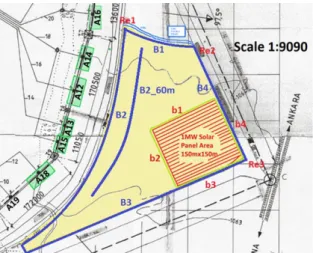
Feasibility study of installation of solar panels on a high power HF antenna land
Tam metin
Şekil
Benzer Belgeler
Utilizing artificial neural network technology, the intelligent solar panel fault detection system is capable of perceiving sun’s position in the sky and estimating the
Furthermore, the results of this research show that sustainable skyscrapers, which are benefited from solar energy design, can be more energy efficient related to use
The decision points (Aksaray, Konya, Karaman, Nevşehir, and Niğde) are put in the rows, and evaluation factors (solar energy potential, surface slope, and capacity) are put in
As the energy impinges upon the Earth’s surface, a portion of it is absorbed and stored by the solid Earth, its water surfaces, and the atmosphere, while the
Use of interest-free financial instruments in the airport finance was introduced with some domestic examples in Turkey and throughout the world; and finally, some suggestions
Performans değerlendirme sisteminden duyulan memnuniyetin bağımlı değişken olarak kabul edildiği ve örgütsel adalet ve boyutlarının (prosedür adaleti, etkileşim adaleti,
Tarık Buğra’nın 1982 yılında kaleme aldığı “Osmancık” adlı romanında, Anadolu’daki dağınık Türk boylarının Kayı boyu etrafında toplanması ve
Santral Operatörleri eğitimi için ha- zırlanan ders programında; başta kul- lanılan araçların bakımlarının öğrenil- mesi, beton hakkında temel bilgilerin öğrenilmesi,
