Growth and Di
fferentiation of Prechondrogenic Cells on Bioactive
Self-Assembled Peptide Nano
fibers
Seher Ustun, Aysegul Tombuloglu, Murat Kilinc, Mustafa O. Guler,* and Ayse B. Tekinay*
Institute of Materials Science and Nanotechnology, National Nanotechnology Research Center (UNAM), Bilkent University, Ankara 06800, Turkey
*
S Supporting InformationABSTRACT: Restoration of cartilage defect remains a challenge, as the current treatments are ineffective to return tissue to its health. Thus, developing therapies for treatment of cartilage tissue damage caused by common joint diseases including osteoarthritis, rheumatoid arthritis, and accidents is crucial. Sulfated glycosaminoglycan molecules are vital constituents of both developing and mature cartilage extracellular matrix. The interplay between regulator proteins and glycosaminoglycan molecules has an essential role in coordinating differentiation, expansion, and patterning during cartilage development. In this study, we exploited the functional role of an extracellular matrix on chondrogenic differentiation by imitating extracellular matrix both chemically by imparting functional groups of native glycosaminoglycans and structurally through peptide nanofiber network. For this purpose, sulfonate, carboxylate, and hydroxyl groups were incorporated on self-assembled peptide nanofibers. We observed that when ATDC5 cells were cultured on functional peptide nanofibers, they rapidly aggregated in insulin-free medium and formed cartilage-like nodules and deposited sulfated glycosaminoglycans shown by Safranin-O staining. Moreover, collagen II and aggrecan gene expressions revealed by qRT-PCR were significantly enhanced, which indicated the remarkable bioactive role of this nanofiber system on chondrogenic differentiation. Overall, these results show that glycosaminoglycan mimetic peptide nanofiber system provides a promising platform for cartilage regeneration.
1. INTRODUCTION
Cartilage tissue faces high rates of exerted stress, strain, and load. However, its avascular, aneural, and alymphatic character results in low regeneration capability and limited healing once injured. For this reason, cartilage deterioration from trauma or diseases such as osteoarthritis presents great clinical signi fi-cance.1Healthy cartilage is a highly organized tissue composed of chondrocytes embedded into a specialized extracellular matrix that consists of mainly collagen and proteoglycans. Chondrocytes are the only metabolic unit of cartilage responsible for turnover, maintenance, and remodeling of the tissue. The solid fraction of tissue, which is composed of a
dense collagen fibrillar network intertwined with a high
concentration of negatively charged proteoglycans, provides cartilage its unique mechanical features in addition to offering biochemical signals to dictate complex cellular responses. The network of collagenfibers provides tensile strength to the tissue and elastic restraint to swelling pressure of proteoglycans.2
Proteoglycans are composed of a core protein and covalently attached variable number of glycosaminoglycan units. Glyco-saminoglycans in cartilage are found in diverse forms including chondroitin sulfate, heparan sulfate, keratan sulfate, dermatan sulfate, and heparin.3High amount of negative charges coming from sulfate and carboxyl groups on glycosaminoglycans are responsible for specific protein−glycosaminoglycan interac-tions.4,5 Due to these intimate protein−glycosaminoglycan interactions, glycosaminoglycans were reported as important regulators in guiding cell response in terms of migration,
attachment, and differentiation during development by
exploiting activity, concentration, and presentation of several
growth factors.6−8 Many regulator molecules acting on
chondrogenesis rely on heparan sulfate glycosaminogly-cans.9−12Perlecan, a heparan sulfate proteoglycan,13functions
Received: July 15, 2012 Revised: November 26, 2012 Published: November 29, 2012
Article pubs.acs.org/Biomac
as a growth factor reservoir, thereby increasing local concentration of growth factors.14 Also, it provides signals to trigger chondrogenic differentiation.15−18 In addition to their biological functions, proteoglycans are highly negatively charged biomacromolecules in cartilage extracellular matrix. The carboxylate and sulfate groups on proteoglycans provide fixed negative charge to extracellular matrix and each proteoglycan-associated negative charge requires a mobile counterion to maintain tissue electroneutrality.2,19 The mobile counterions (e.g., Na+) coming from outside of the tissue result in drawing of water into the tissue and high swelling pressure. This is crucial for mechanical properties and function of cartilage tissue. Hence, negatively charged groups functional in cartilage tissue can be utilized to decorate extracellular matrix-mimicking nanofiber networks.
A number of studies attempted to recapitulate the cell microenvironment to direct chondrogenesis in vitro by manipulating a variety of signals.20−22 In the present study, we utilized bioactive peptide nanofibers in order to construct a chondrogenesis triggering environment. Self-assembled peptide amphiphile nanofibers are versatile scaffolds that enable direct incorporation of various functional peptide moieties. Peptide amphiphile molecules form nanofibers through hydrophobic collapse of alkyl tails in aqueous environment at physiological pH.23 The resulting higher order structure is composed of nanofibers, which are 5 nm in diameter, has a pore size of 5− 200 nm with a water content of more than 99%.24,25 Due to these characteristics, peptide amphiphile nanofibers can mimic native extracellular matrix in terms of structure and function by presenting bioactive signals on the surface of nanofibers.26−28
Here, we investigated the effect of glycosaminoglycan
mimetic self-assembled peptide nanofiber network decorated
with various chemical groups on chondrogenic differentiation of chondroprogenitor ATDC5 cells. ATDC5 is a cell line derived from mouse embryonic carcinoma cells. In the presence of insulin, they show multistep chondrogenic differentiation similar to what is observed during endochondral bone formation.29These cells provide easy handling and straightfor-ward tracking of chondrogenic differentiation due to their distinctive features during differentiation. Incorporating chem-ical groups present in native glycosaminoglycan molecules on a nanofibrous network as a single system enhanced differentiation of chondrogenic cells by providing a chondro-inductive microenvironment. (Figure 1e) Glycosaminoglycan mimetic peptide nanofibers were designed to present chemical groups including sulfonate, carboxylate and hydroxyl (Table 2). During embryonic development, cartilage formation involves a series of complicated and strictly regulated events. Before chondrogenic differentiation, stem cells undergo several processes charac-terized by recruitment and migration of cells to a central core and formation of dense cell−cell interactions resulting in the formation of cell aggregates.30−32 Therefore, the effects of a chondro-inductive microenvironment on differentiation of ATDC5 cells can be traced by analyzing the characteristic
mechanisms of chondrogenic differentiation. ATDC5 cells
formed dense cell−cell interactions and cellular aggregates similar to in vivo chondrogenic differentiation and deposited extensively sulfated glycosaminoglycans on all bioactive peptide
nanofiber systems that we have tested without requiring
external chondrogenic cues. However, when cartilage specific gene expression profiling was examined, a glycosaminoglycan
mimetic peptide nanofiber network presenting sulfonate,
carboxylate, and hydroxyl groups simultaneously prompted
Figure 1.Self-assembled peptide amphiphile nanofibers. (a) Chemical structures of peptide amphiphiles. SEM images showed extracellular matrix mimetic morphology of nanofiber networks NF2 (b) and NF4 (c). (d) Circular dichroism spectra of peptide amphiphile combinations showing that nanofiber networks contain β-sheet secondary structure.
collagen II, aggrecan, and Sox-9 gene expression significantly more than the other nanofiber control systems.
2. EXPERIMENTAL SECTION
2.1. Materials. 9-Fluorenylmethoxycarbonyl (Fmoc) and tert-butoxycarbonyl (Boc) protected amino acids, [4-[α-(2′,4′-dimethox-yphenyl) Fmoc-aminomethyl]enoxy]acetamidonorleucyl-MBHA resin (Rink amide MBHA resin), Fmoc-Glu(OtBu)-Wang resin, and 2-(1H-benzotriazol-1-yl)-1,1,3,3-tetramethyluronium hexafluorophosphate (HBTU) were purchased from NovaBiochem and ABCR. Cover glasses and tissue culture plates (24-well) were purchased from Deckglaser and BD. All other chemicals and materials used in this study were analytical grade and obtained from Invitrogen, Fisher, Merck, Alfa Aesar, and Sigma-Aldrich.
2.2. Synthesis, Purification, and Characterization of Peptide Amphiphile Molecules. Peptide amphiphile molecules used in this study were synthesized by standard solid phase Fmoc chemistry. Rink amide MBHA resin (for SO3-PA and K-Pa) and Fmoc-Glu-(OtBu)-Wang resin (for E-Pa) were used as solid supports. Fmoc groups were cleaved by treating the solid phase with 20% (v/v) piperidine in DMF for 20 min. Fmoc-protected amino acids were dissolved in 10 mL of DMF and activated with O-benzotriazole-N,N,N ′,N′-tetramethyl-uronium-hexafluoro-phosphate (HBTU) and N-ethyl-diisopropyl-amine (DIEA) in a molar equivalency ratio of 2:1.95:3, respectively. Coupling of Fmoc-protected amino acid and growing peptide chains was carried out for 2 h. Fmoc groups were cleaved by treating the solid phase with 20% piperidine/DMF for 20 min. Resin was treated with 10% acetic anhydride for sealing off unreacted amines for 30 min after each coupling. After coupling all Fmoc-protected amino acids, alkyl tail was attached following the same amino acid coupling protocol, using lauric acid. Peptide amphiphiles were cleaved from resin, and side chain protective groups of functional groups were removed in a cleavage step of 2 h with trifluoroacetic acid (TFA)/triisopropylsilane (TIS)/water at the ratio of 95:2.5:2.5. Solution containing the cleavage products was collected at a round-bottomflask and resin was washed several times with DCM. Excess DCM and TFA were removed to a large extent by rotary evaporation. Peptide amphiphile was triturated by adding ice-cold diethylether into the solution and left overnight at −20 °C. Diethylether was decanted after centrifugation at 8000 rpm for 15 min. Product was dissolved in ddH2O, frozen at−80 °C, and freeze-dried for two days.
Peptide amphiphiles were purified by reverse phase HPLC system equipped with Zorbax Extend-C18 21.2× 150 mm column for E-PA and SO3-PA. Pure peptide amphiphile was eluted applying a linear gradient of acetonitrile for 30 min. Molecular mass and purity of peptide amphiphiles were confirmed with Agilent 6530−1200 Q-TOF LC-MS equipped with ESI-MS. Purity by peptide content was monitored at 220 nm. Zorbax Extend-C18 21.2× 150 mm column was used for Lys-PA, and Zorbax Extend C18 column was used for SO3-PA and E-PA. Formic acid (0.1%) in water served as the aqueous phase, while formic acid (0.1%) in acetonitrile gradient served as the organic phase.
2.3. Analysis of Structural and Mechanical Characteristics of Peptide Nanofibers. Oscillatory rheology measurements were performed with an Anton Paar Physica MCR301. For all measure-ments, 25 mm parallel plate was used with 0.5 mm gap. Total gel volume was adjusted tofill the whole cylindrical space between the stage and the plate. PA solutions of 10 mM were freshly prepared and sonicated for 30 min. After loading one PA solution at the center of the stage, counter-charged PA solution was added on it dropwise. Upper plate was brought to 0.5 mm position and gel was incubated in this position for 15 min before measurement. For strain sweep measurements, angular frequency was kept constant at 10 rad/s, and strain was increased between 0.1 and 100%. Storage and loss moduli were recorded at each strain.
Circular dichroism studies were performed with 0.3 mM aqueous solutions of peptide amphiphiles diluted from 1 mM stock solutions by using J-815 Jasco spectrophotometer. All spectra were obtained at a wavelength interval of 190−300 nm. Spectra were obtained at a digital
integration time of 4 s, bandwidth of 1 nm, and data pitch of 0.1 nm. Three subsequent spectra were averaged for each sample.
2.4. Cell Culture. 2.4.1. Monolayer Culturing. ATDC5 cells were cultured as monolayer cultures in 1:1 mixture of DMEM and Ham’s F12 medium supplemented with 5% fetal bovine serum, 10μg mL−1 holo-transferrin and 3 × 10⁻⁸ M sodium selenite in tissue culture plates at standard culture conditions (at 37°C under 5% CO2). To induce chondrogenic differentiation maintenance medium was supplemented with 10μg mL−1of insulin.
2.4.2. Cell Seeding and Cultivation on Peptide Nanofiber Networks. Before cell culture experiments, tissue culture plates were coated with 1 mM peptide amphiphile solutions. Coated plates were left under laminarflow hood for overnight incubation to dry solvent and sterilized under UV lamp for 30 min prior to cell seeding. ATDC5 cells were seeded at a density of 5× 10³cells/cm2in either insulin-supplemented media or insulin-free media on peptide networks or tissue culture plates.
2.5. In Vitro Adhesion, Spreading, and Cell Viability. Adhesion of ATDC5 cells was assessed at 1 and 3 h after seeding cells on each peptide network and glass surface. Prior to experiment, cells were pretreated with 50 μg/mL cycloheximide in serum-free DMEM medium supplemented with 4 mg/mL BSA for 1 h at 37°C and 5% CO2to eliminate the effect of endogenous proteins in initial cell attachment onto surfaces. In this set of experiments, peptide amphiphiles were coated on glass surfaces, and cells were seeded on either coated or uncoated glass surfaces for achieving better resolution during subsequent imaging procedures after staining.
After 1 and 3 h culture of cells, unbound cells were washed with PBS and remaining adhered cells were stained with 1μM calcein AM. Adhered cells were imaged under fluorescence microscope and counted by using Image J. Quantified data was normalized against glass surface.
To monitor spreading characteristics of ATDC5 cells on peptide nanofibers, cells were stained with TRITC conjugated phalloidin that maps local actinfilaments and imaged with confocal microscope or examined under scanning electron microscope (SEM). Cells were seeded on peptide nanofibers and uncoated glass surfaces with ATDC5 expansion medium. After 3 and 48 h of culture, they were fixed with 4% paraformaldehyde/PBS for 10 min and permeabilized for 15 min with 0.1% Triton X-100/PBS. F-actin was stained with TRITC-phalloidin and cell nuclei were stained with TO-PRO-3 iodide. The stained cells were examined under confocal microscope. For imaging cells under SEM, cells were washed with PBS and attached cells werefixed with 2% gluteraldehyde/PBS for 2 h. Following three washing steps with PBS, samples were dehydrated in graded ethanol solutions starting with 20% ethanol and continuing up to absolute ethanol for 10 min at each step. Samples were dried with Tourismis Autosamdri-815B critical point drier, coated with 6 nm Au/Pd, and imaged by FEI Quanta 200 FEG SEM.
On days 1−3, viability of ATDC5 cells seeded on nanofiber networks were quantified by calcein AM staining (Molecular Probes, Invitrogen). After cell seeding in ATDC5 expansion medium, cultures were incubated under standard conditions. At indicated time points, cells werefirst washed with PBS to remove dead cells and then stained with 1μM calcein AM (n = 3 per group). Viable cells were imaged under fluorescence microscope and counted by using Image J. Quantified data was normalized to glass surface.
2.6. Differentiation Analysis. 2.6.1. Morphology Screening. Cells were cultured on peptide nanofibers for 18 days (three wells for each peptide nanofiber), during which 10 random images were taken from each well periodically. Size measurements of aggregates (area, perimeter, major, minor) and number of aggregates were quantified with ImageJ for each frame. For each well, 10 frames were pooled to determine the number of aggregates per well and the average area of aggregates. Average area of each aggregate formed on each well was calculated according to the following: average area of aggregates = total area of aggregates (within 10 frames)/number of aggregates (within 10 frames). Mean values and standard deviations were obtained from three wells.
2.6.2. Analysis of Sulfated Glycosaminoglycan Production. The sulfated glycosaminoglycan content produced by cells on peptide nanofibers or tissue culture plate was analyzed with both Safranin-O staining and dimethylmethylene blue assay, which determine glycosaminoglycan production, on days 3, 7, and 14. For Safranin-O staining, cells were washed with PBS and fixed with 4% paraformaldehyde for 15 min at room temperature. To eliminate nonspecific binding, cells were blocked with 2% BSA/PBS for 30 min after washingfixed cells with PBS. Then cells were treated with 0.1% (w/v) Safranin-O in 0.1% (v/v) acetic acid for 5 min at room temperature. Extensive washing with PBS was performed after Safranin-O treatment to remove unbound dye.
For dimethylmethylene blue (DMMB) assay, cell cultures were digested in papain digestion buffer (100 mM sodium phosphate buffer/10 mM Na2EDTA/10 mML-cysteine/0.125 mg/mL papain) overnight at 65 °C. Total DNA per well was measured with Qubit dsDNA quantitation kit (Invitrogen) according to manufacturer’s instructions. Total dsDNA was used to normalize sulfated glycosaminoglycan content. For DMMB assay diluted chondroitin sulfate standards (from 0 to 35 μg mL−1) were used to generate standard curve. A total of 100μL of DMMB solution (16 mg L−1 1,9-dimethylmethylene blue, 40 mM glycine, 40 mM NaCl, 9.5 mM HCl, pH 3.0) was added on 40μL of papain-digested solutions and standard samples and optical density (OD) of the solutions was measured using 595 nmfilter on microplate reader. The absorbance of the cell-free control groups was subtracted from the absorbance values of the experimental groups.
2.6.3. Immunofluorescence Staining and Imaging. Immunocy-tochemistry was used to analyze expression of collagen II and Sox-9 proteins. Cells were seeded at a density of 2.5× 10⁴ cells/cm2 on peptide nanofibers or glass surfaces in cell culture media with or without insulin. After harvesting on days 3, 7, and 14, cells werefixed in 4% paraformaldehyde/PBS for 10 min and permeabilized in 0.1% Triton X-100 for 15 min. To reduce nonspecific binding, samples were incubated with 10% (w/v) bovine serum albumin/PBS for 30 min and treated with either collagen II primary antibody (Abcam) at 1:200 dilution and Sox-9 primary antibody (Thermoscientific) at 1:300 dilution overnight at 4°C. Then, samples were incubated with Cy3 conjugated goat antirabbit secondary antibody at 1:500 dilution for 1 h at room temperature. Extensive washing with PBS was performed between each step. All samples were counterstained with 1μM TO-PRO-3 (Invitrogen) in PBS for 15 min at RT and mounted with Prolong Gold Antifade Reagent (Invitrogen). Negative controls were obtained by omitting primary antibody and incubating with 1% normal goat serum/PBS. Samples were imaged using confocal microscope (Zeiss LSM510).
2.6.4. Gene Expression Analysis. Gene expression profiles for chondrocyte differentiation (Sox-9, collagen II, and aggrecan) and dedifferentiation (collagen I) were assessed by quantitative RT-PCR analysis. ATDC5 cells were seeded at a density of 2.5× 10⁴cells/cm2 on peptide nanofibers and total RNA was isolated using TRIzol (Invitrogen) according to manufacturer’s instructions. Yield and purity of extracted RNA were assessed by Nanodrop 2000 (Thermoscien-tific). Primer sequences were designed using Primer 3 software (Table 1). cDNA synthesis from RNA and qRT-PCR were performed using SuperScript III Platinum SYBR Green One-Step qRT-PCR Kit
according to manufacturer’s instructions. Reaction conditions were briefly as follows: 55 °C for 5 min, 95 °C for 5 min, 40 cycles of 95 °C for 15 s, 60°C for 30 s, and 40 °C for 1 min, followed by a melting curve to confirm product specificity. The reaction efficiencies for each primer set were evaluated with standard curve using 5-fold serial dilutions of total RNA. For analysis of the expression data, primary gene expression data was normalized by the expression level of GAPDH. A comparative Ct method was used to analyze the results.
2.7. Statistical Analysis. All data are presented as mean± SEM (standard error of the mean). The significance of differences between groups was determined with either one-way or two-way analysis of variance (ANOVA). Differences were considered significant when p < 0.05.
3. RESULTS AND DISCUSSION
3.1. Self-Assembled Peptide Amphiphile Nanofiber
Formation. We utilized four different peptide nanofiber networks by mixing 3 different peptide amphiphile molecules at different ratios in order to clearly show the individual and synergistic effect of functional groups and overall charge effect. (Table 2) Peptide networks presented in this study mimic
native GAGs by forming micrometer lengths of nanofibers with repeating chemical groups (containing carboxylate, hydroxyl, and sulfonate groups) presented on their surface. Lauryl-VVAGEGD-K(p-sulfobenzoyl)-S-Am (SO3-PA) carried sulfo-nate, carboxylate, and hydroxyl groups to mimic sulfonated glycosaminoglycan molecules and it was named according to the sulfonate functionalization. Sulfonate groups similar to sulfate groups, are important functional groups of polysacchar-ide components of extracellular matrix, such as heparan sulfate, however, they differ from sulfate groups in terms of stability against hydrolysis. For this reason, we functionalized PA nanofibers with sulfonate groups present on p-sulfobenzoic acid. This peptide system was previously designed and synthesized by our group and its activity in angiogenesis and neural differentiation was shown. We showed that this peptide nanofiber system encapsulates growth factors and increases their local concentrations.33,34 Through this mechanism, cell differentiation was favored and enhanced on heparin mimetic peptide nanofibers. In addition, in a recent study, these peptide
nanofibers were shown to bind to heparin binding growth
factors through their heparin binding domain and induce their activity, similar to natural heparan sulfate glycosaminoglycans.35 Lauryl-VVAGE (E-PA) carried carboxylate and hydroxyl groups as functional units and was named according to charged amino acid residue (glutamic acid) at the C terminus. Lauryl-VVAGK-Am (K-PA) was a positively charged peptide amphiphile molecule and was used to induce nanofiber formation in the presence of either SO3-PA, E-PA, or both via hydrophobic collapse of alkyl tail andβ-sheet forming unit VVAG23(Figure 1a). All peptides were synthesized by solid phase peptide
synthesis and characterized by LC-MS. (Figure S1a−c)
Hydrophobic-collapse and β-sheet-driven self-assembly of oppositely charged peptide amphiphile molecules resulted in formation of nanofibers, which bear structural resemblance to Table 1. Primers Used for qRT-PCR Expression Analysis
gene primer sequence: forward/reverse product size (bp) Col I 5′-TGACTGGAAGAGCGGAGAGT-3′ 151 5′-GTTCGGGCTGATGTACCAGT-3′ Col II 5′-ACTTGCGTCTACCCCAACC-3′ 123 5′-GCCATAGCTGAAGTGGAAGC-3′ Aggrecan 5′-GGTCACTGTTACCGCCACTT-3′ 175 5′-CCCCTTCGATAGTCCTGTCA-3′ Sox-9 5′-AGGAAGCTGGCAGACCAGTA-3′ 193 5′-CGTTCTTCACCGACTTCCTC-3′
Table 2. List of Nanofiber Formulations Used in This Study
designations combinations net charge nanofiber network 1 (NF 1) E-PA/K-PA neutral (0) nanofiber network 2 (NF 2) E-PA/K-PA negative (−1) nanofiber network 3 (NF 3) SO3-PA/K-PA neutral (0) nanofiber network 4 (NF 4) SO3-PA/E-PA/K-PA negative (−1)
native extracellular matrix. This particular geometry allows peptide nanofibers densely present bioactive groups to cells (Figures 1b,c and S1d,e).26Peptide nanofiber network 1 (NF 1) and peptide nanofiber network 2 (NF 2) contained only carboxylate and hydroxyl bearing E-PA at different concen-trations. Glycosaminoglycan-mimetic nanofiber network 3 (NF 3) and nanofiber network 4 (NF 4) contained SO3-PA, which bore sulfonate, carboxylate, and hydroxyl groups; however, NF 4 also contained E-PA. Each nanofiber system was formed by mixing negatively and positively charged 1 mM peptide solutions. All surfaces were coated with 150 μL/cm2peptide mixtures. Molar ratios of each peptide solution in the mixture were determined according to overall net charges of each nanofiber system. Net charges of E-PA, SO3-PA, and K-PA were−2, −3 and +1, respectively. Overall neutral or negative charge in the gel system was obtained by adjusting the molar ratios of each positively and negatively charged PA solution in the mixture. To attain neutral NF 1, E-PA and K-PA were mixed at 1:2 molar ratio and to attain negatively charged NF 2, molar ratio of E-PA and K-PA was adjusted to 2:1, which resulted in higher carboxylate and hydroxyl amount in NF 2 compared to NF 1. In NF 3 and NF 4, which contained SO3 -PA, sulfonate amount was kept same in both systems. For this reason, neutral NF 3 peptide nanofibers were obtained by mixing solely SO3-PA and K-PA at 1:3 molar ratio, while negatively charged NF 4 peptide nanofibers were obtained by mixing SO3-PA, E-PA and K-PA at 3:4:5 molar ratio. Thus, carboxylate groups were more densely presented on NF 4 peptide nanofiber.
To analyze nanofiber formation of peptide amphiphiles and their mixtures, circular dichroism spectroscopy was employed. E-PA and SO3-PA both had negative net charges around pH 7 and, hence, exhibited characteristic random coil spectra with the minima around 198 nm. Positively charged K-PA had a spectrum similar to the negatively charged peptide amphiphiles, however with a broader signal around 200 nm and a minimum around 220 nm. When K-PA solution was added to neutralize negative charges of E-PA and SO3-PA, random coil signals immediately converted to β-sheet structure with a maximum around 200 nm and minimum around 220 nm (Figure 1d).
These results showed that the nanofiber formation was
predominantly β-sheet driven. Peptide nanofibers offer a
suitable network system for both mimicking the extracellular matrix composition (three-dimensional fibrillar network of cartilage extracellular matrix) and presentation of negatively charged groups found on GAG backbone as a synthetic macromolecule.
Mechanical properties of the gels were investigated with oscillatory rheology. Due to technical limitations, gels used in rheology measurements were different than the gels used in cell culture experiments. However, mechanical properties of the bulk gel can provide a rough estimation (and comparison) of the mechanical properties of the fibrillar network which cells sense when they are cultured on thin gels. To form a gel, 10 mM peptide amphiphile mixtures were prepared. Gel formation process was visible and loss of fluidity could be observed by turning sample vial upside down. Storage (G′) and loss (G″) moduli were measured at varying shear strain and constant
Figure 2.Adhesion, spreading, and viability of ATDC5 cells when cultured on peptide nanofibers. (a) Relative adhesion of ATDC5 cells on the peptide nanofibers after 1 and 3 h. Spreading of ATDC5 cells characterized with actin fiber staining (nuclei stained with TO-PRO3 (red), actin fibers stained with TRITC-conjugated phalloidin (green); b,c,f,g) and SEM imaging (d,e,h,i) at 3 and 48 h. (j) Relative cell viability on days 3, 7, and 14 showed that nanofiber networks are biocompatible.
angular frequency. Strain sweep tests showed that counter-charged PA molecules formed gels which stayed in linear viscoelastic region up to 1% strain. Beyond 1% strain, gels gradually lost mechanical strength, and stability. At 0.5% strain, storage moduli of the gels changed between 1 and 3 kPa, and loss moduli were 200−500 Pa. At this particular strain, all four combinations were similar in terms of storage and loss moduli, but neutralized NF 3 gel was slightly stronger (Figure S1f).
3.2. Viability, Adhesion, and Spreading of Cells on
Peptide Nanofiber Networks. ATDC5 chondrogenic cell
line was used as an in vitro model system. Initial cellular responses were evaluated by investigating adhesion and spreading characteristics of cells on peptide nanofibers. The interactions formed between cells and surrounding micro-environment is crucial for regulation of diverse cellular processes such as proliferation, migration, gene expression, differentiation, and apoptosis. Thus, for a synthetic scaffold to be effective, the initial interaction of cells at the interface of scaffold system should mimic native cell−extracellular matrix interactions to some extent. Peptide amphiphiles self-assembled into nanofibers similar to native cell−extracellular matrix morphology and this morphology was preserved during cell culture studies (Figure S2). Adhesion of cells on the peptide
nanofiber network system at 1 and 3 h were studied. The
number of cells adhered on peptide nanofibers was significantly greater than those that adhered on the glass surfaces (Figure 2a). The interaction of cells with peptide nanofibers was further assessed through staining actin cytoskeleton and examining spreading of cells. Cells seeded on the peptide nanofibers
managed to form prominent actin stress fibers and adhered firmly onto the peptide nanofiber networks (Figures 2b−i and S3).
Cellular viability of ATDC5 cells seeded on the peptide nanofibers was assessed by calcein AM staining. Viability of the cells was compared to cells that were cultured on glass surfaces at varying time points (24, 48, and 72 h). There was no significant difference between cells cultured on the glass surface and peptide nanofibers and viability of the cells on all surfaces were comparable. This indicates that no toxicity was induced by the material. (Figure 2j) Overall, adhesion, spreading, and viability results showed that peptide nanofibers provide a favorable microenvironment for ATDC5 cells.
3.3. Morphological Effects of Nanofiber Networks on
ATDC5 Cells. Dynamic molecular level interactions taking place between cells and peptide nanofiber system dictate the differentiation route and fate of cells. Thus, it is crucial to monitor newly formed tissue constructs in terms of morphology, matrix production, and gene expression. To examine cell responses to peptide nanofibers in longer terms, ATDC5 cells were seeded on either peptide nanofiber networks or tissue culture plates and imaged at different time points. Cells were seeded at a high density in order to enhance spatial cell−cell contacts similar to native development. ATDC5 cells treated with insulin typically commit to chondrogenesis pathway through condensation stage to form cartilage nodules up to 21 days. ATDC5 cells commit to form nodular structures after reaching confluency following growth phase.29,36For the following differentiation studies, ATDC5 cells were cultured
Figure 3.Aggregate formation in the absence of insulin. Light microscope images (c, d, g, h) and SEM images (a, b, e, f) of aggregate formation on NF 2 and NF 4 on days 3 and 7. Number of aggregates (i) and average area of aggregates (j) of ATDC5 cells cultured on all peptide networks in media without insulin. Values represent mean± SEM, n = 3.
either in the absence or presence of insulin on both TCP and peptide amphiphile nanofiber surfaces.
During initial seeding, cells were distributed homogeneously on peptide nanofibers or tissue culture plates, and no cell clusters were observed. Interestingly, after 36 h, cells seeded on the peptide nanofibers presented a rounded morphology similar to cytological characteristics of chondrocytes in vivo, and started to move to a central core and form many independent cellular aggregates that mimic mesenchymal condensation (Figures 3a−h and S4a−h). This spontaneous response arose
on each peptide nanofiber system even in the absence of
insulin, which is known as an essential chondrogenic cue.
On all peptide nanofiber systems, a similar trend was
observed such that the size of aggregates progressively increased while the number of aggregates decreased after longer duration of incubation (Figures 3i,j and S4i,j). This could be caused by formation of smaller aggregates on peptide nanofibers during earlier stages, which give rise to larger aggregates after further incubation. When cells were cultured in insulin-supplemented media, aggregate area was slightly larger and total number of aggregates was less compared to aggregates formed in insulin-free media. However, when total aggregate area was considered, there was no significant effect of insulin. Cells cultured on tissue culture plates in the presence of insulin exhibit much more smaller cartilaginous nodules. (Figure S5). This might be caused by the fact that ATDC5 cells cultured on TCP did not commit to chondrogenic differentiation as fast as cells cultured on peptide nanofibers.
Considering the characteristics of the aggregates, cells tend to form larger aggregates in fewer numbers (in the range of 80− 330) on NF 3, 2, and 1 compared to NF 4. On the contrary, the trend was the opposite on NF 4; cells formed smaller aggregates in higher numbers (∼270 to 430). The varying size and number of aggregates implied different responses of cells to different peptide networks in terms of chondrogenic differentiation. In terms of total aggregate area, results showed that there is a consistent change in each group over time (Figure S6). Total aggregate area was found to increase by day 7 followed by a consistent decrease after that (until day 9). The increase was due to formation of new aggregates and following decrease could be due to compaction those cell aggregates following merging of loosely formed aggregates. It is known that compaction of cell aggregates can be seen as a step during condensation of limb progenitor cells.37
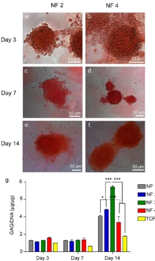
3.4. Cartilaginous Matrix Deposition. Having observed that cellular aggregates similar to cartilage-like nodules formed on peptide nanofiber networks, cellular differentiation was further characterized in terms of matrix production and gene expression. Cartilage extracellular matrix is mainly composed of collagenfibers and large proteoglycan molecules giving cartilage tissue its unique mechano-physical characteristics. For this reason, glycosaminoglycan deposition by ATDC5 cells, an important indicator of cartilage extracellular matrix, was investigated. Safranin-O staining was performed in order to visualize sulfated glycosaminoglycan accumulation. Safranin-O is a cationic dye that binds to glycosaminoglycans stochio-metrically. Thus, secreted cartilaginous extracellular matrix can be indexed by Safranin-O staining and the intensity of staining is directly proportional to the glycosaminoglycan content. Cell aggregates formed on each nanofiber network stained discretely with Safranin-O with clear boundaries showing accumulation of sulfated glycosaminoglycans. (Figures 4a−f and S7a−f) No
clear intensity differences were observed between cell
aggregates formed on different peptide nanofibers. ATDC5
cells grown on tissue culture plates did not form any aggregates and stained faintly.
Even though safranin-O staining is a common indicator for deposition of cartilaginous matrix, it may not be sensitive enough to reflect small differences in proteoglycan content deposited on different peptide nanofibers. Thus, we quantified sulfated glycosaminoglycan production by cell aggregates on
various nanofiber networks on days 3, 7, and 14 by DMMB
assay, which is a rapid method for quantification of sulfated glycosaminoglycans. DMMB assay revealed higher amounts of sulfated glycosaminoglycan deposition on peptide nanofibers compared to tissue culture plates. This showed that the peptide
nanofiber networks induced production and deposition of
sulfated glycosaminoglycans. On days 3 and 7, there was no
significant difference between GAG depositions of cells
cultured on different peptide networks, however, on day 14, cells cultured on NF 3 exhibited highest (∼7) GAG/DNA ratio (Figures 4g and S7g). Considering cell response in the sense of aggregate formation and GAG deposition together, there is a distinctive correlation. When cells formed larger aggregates in fewer numbers, they accumulated more sulfated GAGs (NF 3), however, when cells formed smaller aggregates in higher numbers, they accumulated less sulfated GAGs (NF 4).
Figure 4. Safranin-O and DMMB staining for GAG incorporation. Safranin-O staining of aggregates cultured on NF 2 network (a,c,e) and NF 4 network (b,d,f) on days 3, 7, and 14. (g) DMMB assay showed sulfated glycosaminoglycan content of ATDC5 aggregates normalized to DNA content on days 3, 7, and 14.
To further analyze the effect of peptide nanofibers on chondrogenic differentiation, cells were immunostained for cartilage specific proteins (e.g., collagen II and Sox-9). Cells cultured on all of the peptide nanofiber networks expressed collagen II on days 3, 7, and 14 and Sox-9 mostly on day 3 (Figures S8) and we also observed staining on cells culture on TCP (Figure S9). Because Sox-9 is a transcription factor, its expression was localized in or around nucleus. On day 3, its expression could be observed on all groups. However, on days 7 or 14, its expression level was much lower probably due to Sox-9 being an early marker of chondrogenesis (Figure S10).
3.5. Gene Expression Profiles. Gene expression profiles of cells cultured on peptide networks coated and uncoated surfaces were analyzed in order to understand differential effects of various peptide nanofiber systems on the progression of chondrogenic differentiation of cells. Expression of cartilage specific genes such as aggrecan, collagen II, Sox-9, and collagen I were examined on days 3, 7, and 14. As mentioned above, Sox-9 is a key chondrogenic transcription factor expressed in cells undergoing cellular condensation step and is required for the expression of definitive cartilage markers like collagen II and aggrecan.38Consistent with aggregate formation and matrix deposition, Sox-9 was upregulated by at least∼1.5-fold when cells were cultured on NF 1 and NF 2 and by∼3-fold when cells were cultured on NF 3 and NF 4 in the absence of insulin
on day 3. There was a significant difference between the
glycosaminoglycan mimetic peptide nanofiber networks deco-rated with sulfonate groups and the ones that did not have these groups on day 3 (Figures 5c and S11c). The trend continued on day 7 with modest decrease. Aggrecan expression
profile was also investigated since aggrecan is a cartilage-specific proteoglycan core protein, which is one of the downstream targets of Sox-9 in the chondrogenic differentiation pathway. Aggrecan expression was at considerable amount (in the range of 1.82−3.38-fold) on all of the peptide nanofiber systems yet it reached its highest value (day 3, 5.85; day 7, 8.65) on NF 4, which was significantly different than other peptide nanofibers (Figures 5a and S11a). In parallel to aggrecan expression, collagen II expression was also upregulated by cells cultured on peptide networks (in the range of 3.29−6.68) and again its highest fold change value (day 3, 31; day 7, 38) was observed when cells were cultured on NF 4 (Figures 5b and S11b). In addition, we analyzed ratio of collagen II to collagen I, since collagen II/I ratio is another indicator for chondrogenic differentiation. Collagen I is one of the dedifferentiation markers and it is found in fibrocartilage. Consistent with expression of other genes, the collagen II/I ratio was significantly higher in cells cultured on NF 4 network (Figures 5d and S11d).
Overall, aggregate formation was observed on each peptide nanofiber system and GAG deposition was considered as the evidence of chondrogenic differentiation. This was validated
through safranin-O staining and quantified through DMMB
assay. Gene expression analysis further revealed that cartilage specific genes are highly expressed in cells that were cultured on peptide nanofibers compared to standard tissue culture plate. Cumulatively considering aggregate size number, GAG deposition, and gene expression profiles, we conclude that each peptide construct promoted chondrogenic differentiation at varying extent. ATDC5 cells formed larger aggregates in
Figure 5.Gene expression analysis in the absence of insulin: (a) aggrecan gene expression; (b) collagen II gene expression; (c) Sox-9 gene expression; (d) collagen II/I gene expression ratio. The expression level of each gene was normalized against TCP and GAPDH was used as the internal control. Values represent mean± SEM, n = 6 (***p < 0.0001, **p < 0.01, *p < 0.05).
fewer numbers, deposited more sulfated GAGs on NF 3−1 and expressed cartilage specific genes in smaller quantity (aggrecan, 1.82−3.38-fold; collagen II, 3.29−6.68). This trend was the opposite of NF 4 where ATDC5 cells formed more aggregates in smaller sizes, deposited less-sulfated GAGs, and expressed cartilage-specific genes at the highest quantity compared to the rest of the peptide networks. We conclude that high gene expression does not necessarily translate to high sulfated GAG deposition. On the other hand, this result does not mean that the total amount of GAGs does not correlate with the gene expression profile, because the assay that we have utilized to measure GAG quantity, DMMB assay, is ubiquitously used to quantify deposited sulfated GAG and it is not sensitive to reveal cartilage specific composition of GAG. Thus, gene expression analysis using qRT-PCR is more reliable to assess cellular behaviors and gene expression analysis results are considered more informative and accurate for the present study. The superior chondrogenic potential of NF4 was primarily attributed to the synergistic effect of different peptide amphiphile molecules in one system, because NF 4 was composed of mainly E-PA and SO3-PA that bring carboxylate, hydroxyl, and sulfonate groups together at proper ratio. On the other hand, the effect of overall charge might also play a role in the difference between NF 3 and NF 4, because both of these peptide networks contained sulfonate, hydroxyl, and carbox-ylate groups. However, overall charge difference did not make a significant difference between cells cultured on NF 1 (neutral) and NF 2 (negative), both of which contained the same type of molecules. Thus, the ratio of the functional groups might play a stronger role than the overall charge of the peptide network. In addition, it is important to remark that formation of cellular aggregation and deposition of cartilaginous matrix on each nanofiber network point the effect of nanofibrous network on evoking differentiation of chondroprogenitor cells.
4. CONCLUSION
Degeneration of cartilage tissue is a significant health problem due to low regeneration capacity of this tissue. Extensive studies have previously been carried out to provide an effective solution to regenerate cartilage defects. Here, we developed a model system using chondro-inductive glycosaminoglycan mimetic peptide amphiphile nanofibers decorated with several charged groups. In this model, chondrogenic differentiation of ATDC5 cells was observed in the absence of any external bioactive factors. We developed peptide nanofiber networks equipped with differential effects of chemical groups such as hydroxyl, carboxylate, and sulfonate. Although peptide nanofiber systems
were different from each other in terms of chemical
composition, all of the formulations that were utilized supported growth and differentiation of ATDC5 cells, which was established with morphological changes and deposition of a cartilaginous matrix. However, detailed gene expression profiling clearly showed that the synergistic effect of sulfonate, carboxylate, and hydroxyl groups in NF 4 formulation was more effective for inducing chondrogenic differentiation. Overall, our results showed that glycosaminoglycan mimetic peptide amphiphile nanofiber networks provide a promising platform for cartilage regeneration by providing a chondro-inducive microenvironment.
■
ASSOCIATED CONTENT*
S Supporting InformationLC-MS measurements, oscillatory rheology results, SEM images, immunocytochemistry images, additional information on aggregate formation, safranin-O staining, and qRT-PCR results. This material is available free of charge via the Internet at http://pubs.acs.org.
■
AUTHOR INFORMATIONCorresponding Author
*E-mail: [email protected] (M.O.G); atekinay@ unam.bilkent.edu.tr (A.B.T.).
Notes
The authors declare no competingfinancial interest.
■
ACKNOWLEDGMENTSWe would like to thank H. Ceylan, M. Kilinc, Y. Dagdas, and A. Ozkan for SEM imaging. We also would like to thank Z. Erdogan and Z. E. Ulger for their technical help. This work was funded partially by Loreál Young Women Investigator Award and TUBITAK Grant No. 111M710. S.U. is supported by TUBITAK-BIDEB Ph.D. fellowship. M.O.G. acknowledges support from the Turkish Academy of Sciences Distinguished Young Scientist Award (TUBA-GEBIP).
■
REFERENCES(1) Hunziker, E. B. Osteoarthr. Cartilage 2002, 10, 432−463. (2) Athanasiou, K. A.; Darling, E.; Hu, J. Articular Cartilage Tissue Engineering; Morgan and Claypool Publisher Series: U.S.A., 2009.
(3) Knudson, C. B.; Knudson, W. Semin. Cell Dev. Biol. 2001, 12, 69− 78.
(4) Hileman, R. E.; Fromm, J. R.; Weiler, J. M.; Linhardt, R. J. Bioessays 1998, 156−167.
(5) Kuschert, G. S.; Coulin, F.; Power, C.; Proudfoot, E.; Hubbard, R. E.; Hoogewerf, J.; Wells, T. N. Biochemistry 1999, 38, 12959−12968.
(6) Hynes, R. O. Science 2009, 326, 1216−1219.
(7) Jiao, X.; Billings, P. C.; O’Connell, M. P.; Kaplan, F. S.; Shore, E. M.; Glaser, D. L. J. Biol. Chem. 2007, 282, 1080−1086.
(8) Rodgers, K. D.; San Antonio, J. D.; Jacenko, O. Dev. Dyn. 2008, 237, 2622−2642.
(9) Kirn-Safran, C. B.; Gomes, R. R.; Brown, A. J.; Carson, D. D. Birth Defects Res., Part C 2004, 72, 69−88.
(10) Fisher, M. C.; Li, Y.; Seghatoleslami, M. R.; Dealy, C. N.; Kosher, R. Matrix Biol. 2006, 25, 27−39.
(11) French, M. M.; Smith, S. E.; Akanbi, K.; Sanford, T.; Hecht, J.; Farach-Carson, M. C.; Carson, D. D. J. Cell Biol. 1999, 145, 1103− 1115.
(12) Roughley, P. J. Eur. Cells Mater. 2006, 12, 92−101.
(13) Iozzo, R. V.; Cohen, I. R.; Grässel, S.; Murdoch, A. D. Biochem. J. 1994, 302, 625−639.
(14) Yang, W. D.; Gomes, R. R., Jr; Alicknavitch, M.; Farach-Carson, M. C.; Carson, D. D. Tissue Eng. 2005, 11, 76−89.
(15) Costell, M.; Gustafsson, E.; Aszódi, A.; Mörgelin, M.; Bloch, W.; Hunziker, E.; Addicks, K.; Timpl, R.; Fässler, R. J. Cell Biol. 1999, 147, 1109−1122.
(16) French, M. M.; Gomes, R. R.; Timpl, R.; Höök, M.; Czymmek, K.; Farach-Carson, M. C.; Carson, D. D. J. Bone Miner. Res. 2002, 17, 48−55.
(17) Hassell, J.; Yamada, Y.; Arikawa-Hirasawa, E. Glycoconjugate J. 2003, 19, 263−267.
(18) Melrose, J.; Hayes, A. J.; Whitelock, J. M.; Little, C. B. Bioessays 2008, 30, 457−469.
(19) Maroudas, A.; Muir, H.; Wingham, J. Biochim. Biophys. Acta 1969, 177, 492−500.
(20) Ghosh, S.; Laha, M.; Mondal, S.; Sengupta, S.; Kaplan, D. L. Biomaterials 2009, 30, 6530−6540.
(21) Varghese, S.; Hwang, N. S.; Canver, A. C.; Theprungsirikul, P.; Lin, D. W.; Elisseeff, J. Matrix Biol. 2008, 27, 12−21.
(22) Ghone, N. V.; Grayson, W. L. J. Cell. Physiol. 2012, 1−29. (23) Niece, K. L.; Hartgerink, J. D.; Donners, J. J. J. M.; Stupp, S. I. J. Am. Chem. Soc. 2003, 125, 7146−7147.
(24) Mammadov, R.; Tekinay, A. B.; Dana, A.; Guler, M. O. Micron 2012, 43, 69−84.
(25) Holmes, T. C.; de Lacalle, S.; Su, X.; Liu, G.; Rich, A.; Zhang, S. Proc. Natl. Acad. Sci. U.S.A. 2000, 97, 6728−6733.
(26) Silva, G.; Czeisler, C.; Niece, K. L.; Beniash, E.; Harrington, D.; Kessler, J.; Stupp, S. I. Science 2004, 303, 1352−1355.
(27) Ceylan, H.; Tekinay, A. B.; Guler, M. O. Biomaterials 2011, 32, 8797−8805.
(28) Storrie, H.; Guler, M. O.; Abu-Amara, S. N.; Volberg, T.; Rao, M.; Geiger, B.; Stupp, S. I. Biomaterials 2007, 28, 4608−4618.
(29) Shukunami, C.; Shigeno, C.; Atsumi, T.; Ishizeki, K.; Suzuki, F.; Hiraki, Y. J. Cell Biol. 1996, 133, 457−468.
(30) Hall, B. K.; Miyake, T. Int. J. Dev. Biol. 1995, 39, 881−893. (31) Hall, B. K.; Miyake, T. Bioessays 2000, 22, 138−147.
(32) Goldring, M. B.; Tsuchimochi, K.; Ijiri, K. J. Cell. Biochem. 2006, 97, 33−44.
(33) Mammadov, R.; Mammadov, B.; Toksoz, S.; Aydin, B.; Yagci, R.; Tekinay, A. B.; Guler, M. O. Biomacromolecules 2011, 12, 3508− 3519.
(34) Mammadov, B.; Mammadov, R.; Guler, M. O.; Tekinay, A. B. Acta Biomater. 2012, 8, 2077−2086.
(35) Mammadov, R.; Mammadov, B.; Guler, M. O.; Tekinay, A. B. Biomacromolecules 2012, 13, 3311−3319.
(36) Atsumi, T.; Miwa, Y.; Kimata, K.; Ikawa, Y. Cell Differ. Dev. 1990, 30, 109−116.
(37) Barna, M.; Niswander, L. Dev. Cell 2007, 12, 931−941. (38) DeLise, A. M.; Fischer, L.; Tuan, R. S. Osteoarthr. Cartilage 2000, 8, 309−334.