1
Journal of Physics D: Applied Physics
J. Phys. D: Appl. Phys. 47 (2014) 075107 (6pp) doi:10.1088/0022-3727/47/7/075107
Highly asymmetric transmission of linearly
polarized waves realized with a
multilayered structure including chiral
metamaterials
Zhaofeng Li, Mehmet Mutlu and Ekmel Ozbay
Nanotechnology Research Center, Department of Physics, and Department of Electrical and Electronics Engineering, Bilkent University, Bilkent, 06800 Ankara, Turkey
E-mail: [email protected]
Received 2 October 2013, revised 12 December 2013 Accepted for publication 24 December 2013 Published 29 January 2014
Abstract
We numerically and experimentally demonstrate highly asymmetric transmission of linearly polarized waves with a multilayered metallic structure. The whole structure has a
subwavelength thickness and consists of a thin slab of chiral metamaterial sandwiched between two 90◦ twisted linear polarizers. The chiral metamaterial is made of two sets of twisting cross wires that can rotate the polarization by 90◦ at resonance, and the two linear polarizers are simple metallic grating polarizers. The operation principle of the whole structure can be well interpreted by using the Jones matrix method. Our experimental results also verify that chiral metamaterials can be safely integrated into complex structures and treated as an effective medium as long as their resonant modes are not affected by the environment.
Keywords: chiral metamaterials, asymmetric transmission, linear polarizer (Some figures may appear in colour only in the online journal)
1. Introduction be realized by planar chiral structures consisting of only a
single layer of meta-atoms [21–26]. Furthermore, asymmetric
Research on the phenomenon of the asymmetric transmission transmissions of linearly and circularly polarized waves can of light waves has been a hot topic for a long time, since it be achieved simultaneously with a thin structure composed plays an indispensable role in many optical systems. One of three-dimensional (3D) meta-atoms [27,28]. The effects conventional way to achieve the asymmetric transmission of of asymmetric transmissions for LP waves can be used light is to take advantage of the non-reciprocity that can to design polarization transformers [16,29] and diode-like be obtained by using magneto-optical media or nonlinear devices [15,20]. The effect of asymmetric transmissions media [1–4]. Recently, it was demonstrated that asymmetric for circularly polarized waves can be used to manipulate the
light propagation can also be realized by the breaking of resonant modes of a ring resonator [21].
parity-time symmetry with complex optical potentials [5]. Inthisreport, weproposeamultilayeredmetallicstructure Meanwhile, asymmetric but still reciprocal transmissions to realize extremely asymmetric transmission of LP waves. by using conventionally isotropic and linear materials have In this multilayered metallic structure, we have included also attracted much research effort. For instance, the a thin slab of chiral metamaterial to take advantage of its asymmetric transmissions of linearly polarized (LP) waves property of rotating a linear polarized incident wave into its can be realized by using nonsymmetrical grating structures cross polarized wave. The following sections are arranged as [6–11], two mutually twisted grating structures [12,13], follows. In section 2, we introduce the operation principle of multilayered anisotropic chiral metamaterials [14–19], and the multilayered metallic structure by using the Jones matrix a composite structure consisting of symmetric gratings with method. Insection3,weshowthesimulationandexperimental a subwavelength slit and a polarization rotator [20]. The results together with some discussions. Conclusions are asymmetric transmissions of circularly polarized waves can presented in section 4.
0022-3727/14/075107+06$33.00 © 2014 IOP Publishing Ltd Printed in the UK
2. Operation principle
The transmission of coherent electromagnetic waves through a slab of a dispersive medium that is embedded in vacuum or air can be described by means of complex Jones matrices T [27,28,30]. Consider a normally incident plane wave propagating in the +z direction, and its electric field is Ei(r,t) = (Ix,Iy)T ei(kz−ωt), with angular frequency ω, wave vector k, and complex amplitudes Ix and Iy in the x and y directions, respectively. The transmitted wave is given by Et(r,t) = (Tx,Ty)T ei(kz−ωt). Here, the incident and transmitted waves are decomposed into the linear base with the base vectors parallel to the coordinate axes, i.e., the x- and y-polarized waves. The complex amplitudes of the incident waves and transmitted waves can be related by the T matrix
[28],
The index f indicates the forward propagation. For the fixed coordinate system, the wave propagation in the backward direction is equal to a situation wherein the sample is rotated by 180◦ with respect to either the x or y axis. For a medium made of reciprocal materials, applying the reciprocity theorem of four-port systems renders the T matrix for the backward propagation T b [28]
. (2)
These components (A, B, C, and D) obey fixed relations for certain symmetries of the medium [28]. From equations (1) and (2), the asymmetric transmission for a given linear base vector can be defined as the difference between the transmitted intensities for different propagation directions as,
(3) According to equation (3), the asymmetric transmission of y-polarized LP waves is the reverse of that of x-y-polarized LP waves. Therefore, in the following, we will only discuss the asymmetric transmission for x-polarized waves for the sake of conciseness.
An idea asymmetric transmission should be that in one direction the transmission is unity while in the opposite direction the transmission is zero and, therefore, the asymmetric transmission is also unity. This requires the diagonal components of the T matrix (A and D) to be zero, and one of the off-diagonal components (B or C) to be zero while the other one is unity, such as,
. (4)
It has been pointed out that a one layered metallic structure (a planar structure) is not enough to achieve the asymmetrictransmissionofLPwavesbecausetheoff-diagonal components of its T matrix are equal (the component B
Figure 1. Schematics for the multilayered structure consisting of a slab of chiral metamaterial sandwiched between two grating polarizers A and B that are mutually twisted by 90◦. The distance d
between the polarizer and the chiral slab is 1mm in our simulations and experiments. The periodic constants in both the x and y directions are 13mm.
is equal to C) [28]. Thus, we must use multilayered metallic structures to accomplish this task. Fortunately, for a multilayered structure, its transmission properties can be obtained by the cascaded multiplication of the Jones matrices if the reflection effects between the adjacent layers are not significant. According to this idea, we have designed a multilayered metallic structure that consists of one slab of chiral metamaterial sandwiched between two 90◦ twisted grating polarizers. Figure 1 shows the schematics of the multilayered metallic structure.
An ideal metallic grating polarizer has a T matrix as in the following,
(5) if the metallic wires are along the y direction. For the case when the metallic wires are along the x direction, the T matrix is,
. (6)
At the chiral resonance frequencies, the T matrix for an idea chiral metamaterial slab that has C4 symmetry with respect to the z axis is the following,
. (7)
Now, the T matrix of the whole multilayered structure in figure 1 can be obtained by multiplying the corresponding T matrices of each slab as following,
,
, (8)
Figure 2. The simulation results of the transmission curves for the slab of chiral metamaterial alone and the polarizer A alone. For the uniaxial chiral slab, Tyy =Txx, and Txy =−Tyx. For the grating
structure, Tyx =Txy = 0.
wherethetrivialphaseinformationresultedfromtheinterspace between the polarizers and the chiral slab is neglected. Thus, we have obtained a structure with the asymmetric transmission of unity for LP waves.
3. Results and discussions
In figure 1, the grating polarizers (A and B) are composed of long continuous metallic (copper) wires patterned on an FR4 printed circuit board (εr = 4.4 with a dielectric loss tangent of 0.025). The thicknesses of the copper and FR4 board are 30µm and 1mm, respectively. The periodic constant of the grating is 1.3mm and the width of the copper wires is 0.8mm. The slab of chiral metamaterial consists of two layered cross wires mutually twisted by 40◦ patterned on a Teflon substrate (εr = 2.08 with a dielectric loss tangent of 0.0004). The thicknesses of the copper and Teflon board are 30µm and 1mm, respectively. The cross wires have a length of 12mm and a width of 1mm. The periodic constants in both the x and y directions are 13mm. The same chiral metamaterial has been studied previously [31].
To study this multilayered structure, we have conducted numerical simulations. The simulation works were carried out by using CST microwave studio (Computer Simulation Technology GmbH, Germany), wherein the finite integration techniquewasapplied. Theperiodicboundaryconditionswere applied to the x and y directions, and the absorbing boundary conditions were applied to the z direction. Figure 2 shows the simulation results of the transmission curves for the grating polarizers and chiral metamaterial before they are combined into a whole structure. Although our structures cannot be seen as idea polarizers and a chiral medium, their transmission characters are qualitatively close to the ideal case. At the chiral resonant frequency of 10.66GHz, the T matrix of the chiral slab is [0.025 0.938; −0.938 0.025]. Meanwhile, the T
matrices of the polarizer A and B are [0.860 0; 0 0.002] and [0.002 0; 0 0.860], respectively. According to equation (8), the T matrix of the whole structure is calculated to be [0 0.694; 0 0], if the reflection effects are neglected.
Figure 3 shows the simulation results of the transmission curves for the whole structure where the distance d between the grating polarizer and the chiral metamaterial is set to be 1mm, as shown in figure 1. Figure 3(a) shows the amplitude transmissions of LP waves with the E field polarized in the x direction, which is incident from the +z and −z directions. It is clearly seen that all the transmissions are quite low except for the Tyx curve for the +z direction in the frequency band around the chiral resonance. At the chiral resonant frequency of 10.44GHz, the T matrix of the whole structure is [0.035 0.815; 0.003 0.035] where the trivial phase information is neglected. It is noticed that the chiral resonant frequency (10.44GHz) of the whole structure is slightly lower than that of the chiral slab alone (10.66GHz).
In order to understand the possible mechanisms for this slight change of the chiral resonant frequency, we have done additional simulations in which we replaced the two grating
polarizers with two bare FR4 boards at the same positions. Figure 4 shows the simulation results for the chiral slab adding two bare FR4 boards and the chiral slab alone. It is found that the chiral resonant frequency shifted from 10.66GHz to 10.44GHzaftertheadditionoftwobareFR4boards. Basedon the simulation results of figures 3(a) and 4, it is clear that the change of the chiral resonant frequency is due to the closely placed FR4 boards (which have a higher dielectric constant thanair). Italsoimpliesthatthebaremetallicgratingstructures have negligible effects on the chiral resonant frequency.
Furthermore, we checked the quality (Q) factors of the Tyx curves for the chiral slab alone and the whole structure consisting of chiral slab and two grating polarizers. Q is definedintermsoftheratiooftheenergystoredintheresonator to the energy lost per cycle. The Q factors can be calculated mathematically by the definition , where fr is the resonant frequency, and f is the half power bandwidth. The Q factors are about 30 and 60 for the chiral slab alone and the whole structure, respectively. The Q factor of a resonator is
mainly affected by two kinds of energy losses. One loss is the energy dissipated in the materials of the resonator, and the other is the radiation loss. For the structures studied here, the energy dissipated in the materials of the resonator is only a small fraction of the radiation loss (detailed results not shown here), therefore we mainly consider the radiation loss. For the chiralslabalone, whenitresonatesitcanradiateenergyinboth +z and −z directions and in both x- and y-polarized waves. However, the situation is different for the whole structure consistingofchiralslabandtwogratingpolarizers. Thegrating structures have a high reflectivity for LP waves parallel to the metallic wires, while they are nearly transparent for LP waves perpendicular to the metallic wires. Now, the chiral resonator can only radiate energy freely in the +z direction with a ypolarized wave and in the −z direction with an x-polarized wave. Other radiations are mostly reflected back. Therefore, the radiation loss is approximately reduced to half of the value of the chiral slab alone. Consequently, the Q factor of the wholestructureincreasedtoabout60. Furthermore, theeffects of the reflections by the two grating polarizers result in the enhanced transmission peak of the Tyx. Therefore, the Tyx
component (0.815) of theT matrix of the whole structure is higher than the corresponding one (0.694) that was calculated based on equation (8) where reflection effects are neglected. It
Figure 4. The comparison of the simulation results between the chiral slab alone and the chiral slab adding two bare FR4 boards.
Figure 3. The simulation results for the whole structure. (a) The amplitude transmission curves of Txx and Tyx for both the +z and −z
should be emphasized that this increase of Tyx is obtained with the cost of a narrower transmission curve (higher Q factor) as shown in figure 3(a). Figure 3(b) shows the total transmitted power for x-polarized waves that are incident from the +z and −z directions. In the frequency near 10.5GHz, the difference of the transmitted power reaches nearly 30dB.
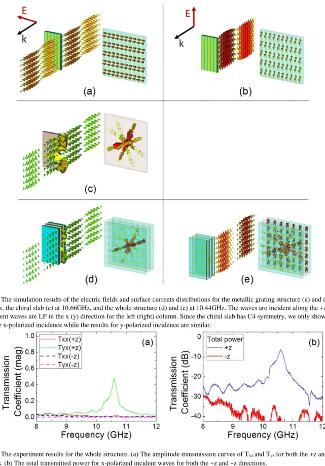
To better understand the physical insight of the asymmetric transmission, we give the details of the electric fields and surface currents distributions of the grating structure (at 10.44GHz), the chiral slab (at 10.66GHz), and the whole structure (at 10.44GHz) in figure 5. For the grating structure, it is nearly transparent for an x-polarized wave but reflects back most of the y-polarized wave, as shown in figures 5(a) and (b). For the chiral slab, the x-polarized incident wave is transformed into a y-polarized output wave at the chiral resonant frequency, as shown in figure 5(c). Due to its C4 symmetry, the y-polarized incident wave is transformed into an x-polarized output wave at the chiral resonant frequency. For the purpose of clarity, the results for a y-polarized incident wavearenotincludedinfigure5. Correspondingly, thesurface currents in the cross wires are antiparallel, similar as the results published previously [32]. For the whole structure, it transforms the x-polarized incident wave into a y-polarized output wave at the chiral resonant frequency, as shown in figure 5(d). Correspondingly, the surface currents mainly concentrate on the cross wires and remain antiparallel. On the other hand, it reflects back most of the y-polarized incident wave, and there is no significant surface current on the cross wires, as shown in figure 5(e).
In order to verify the above designed structure, we fabricated the chiral structures with a dimension of 26cm by 26cm. The side length of the samples is about eight times bigger than the operation wavelength (about 3cm). The transmission coefficients were measured by using an HP8510C network analyser with two standard horn antennas in an anechoic chamber. The horn antennas have an operation bandwidth from 7.5GHz to 12.8GHz. During the experiment, the distance between the samples and the antennas are kept at 30cm. A LP electromagnetic wave (E field in the x direction) is incident on the structure. On the other side of the structure, we measured the transmitted field in the x and y polarizations (Txxand Tyx). Thus, we have measured the transmissions for the +z and −z directions. Figure 6(a) shows the experimental results of Txxand Tyx in both the +z and −z directions. At the chiral resonant frequency of 10.59GHz, the T matrix of the whole structure is [0.021 0.479; 0.001 0.017] where the trivial phase information is neglected. Figure 6(b) shows the total transmitted power for x-polarized waves that are incident from the +z and −z directions. In the frequency near 10.59GHz, the difference of the transmitted power is more than 30dB. The small differences between the results of experiments and simulations might be due to the fabrication imperfections and scattering effects between the sample and the antennas during the measurement. Nevertheless, our experiment has successfully verified the simulation results and the design principle for multilayered structures with
asymmetric transmissions of LP waves. It should be noted that in our previous study, two closely stacked chiral slabs may couple to each other and therefore have a new chirality differentfromasinglechiralslab[31]. However, inthepresent simulations and experiments, we found that the physical characters of the chiral slab have only very little changes when theyarestackedcloselywithmetallicgratingpolarizers. These results show that chiral metamaterials can be safely integrated into complex structures as long as their resonant modes are not affected by the environment.
It is noteworthy that in the simple principle proposed here, the reflection effects are not included in the calculations. This is approximately valid when the reflection effects are relatively
small. However, if the reflection effects are significant, the present simple principle may give incorrect results. In this case, one needs to apply the rigorous transfer matrix method for anisotropic media [33].
We have previously reported two different structures for asymmetric transmissions of LP waves [16,20]. In the work of
[16], we took advantage of the effects of magnetoelectric coupling and electromagnetic wave tunnelling. This design requires the dimensions of the components being precisely selected and fabricated, or the tunnelling effect will become weak. In the work of [20], the resonant frequency of the polarization rotator must coincide with the frequency of the Figure 5. The simulation results of the electric fields and surface currents distributions for the metallic grating structure (a) and (b) at 10.44GHz, the chiral slab (c) at 10.66GHz, and the whole structure (d) and (e) at 10.44GHz. The waves are incident along the +z direction. The incident waves are LP in the x (y) direction for the left (right) column. Since the chiral slab has C4 symmetry, we only show the results for x-polarized incidence while the results for y-polarized incidence are similar.
Figure 6. The experiment results for the whole structure. (a) The amplitude transmission curves of Txx and Tyx for both the +z and −z
strongest enhanced transmission in the design and fabrication, or the transmission will decrease rapidly. On the contrary, in the structure presented here, the grating polarizer can operate well in a very broad bandwidth. One only needs to consider the resonant frequency of the chiral slab. Furthermore, one can use any other type of chiral slabs to substitute the cross wires structure and obtain similar results. Our simulation results (details not shown here) have shown that a ‘U’-shaped chiral metamaterial slab [34] and a complementary chiral metamaterial slab [35] can be used to substitute the cross wires structure to obtain similar asymmetric transmissions. Besides, due to the loss in the FR4 boards, the performance of our grating polarizers are not as good as conventional highperformance polarizer filters. Therefore, one can replace the grating polarizers with high-performance polarizer filters to enhance the transmission of the whole structure. Based on the above arguments, the proposed design in this report is more flexible than previous designs [14–20] and can be easily used in varied applications.
4. Conclusions
In conclusion, we have proposed a multilayered structure for achieving the asymmetric transmission of linearly polarized waves, and its operation principle can be understood based on the method of the Jones matrix. The multilayered structure has subwavelength thickness and consists of one thin slab of chiral metamaterial sandwiched between two 90◦ twisted grating polarizers. Both our simulation and experiment results show that this structure can be used to achieve highly contrast asymmetrictransmissionforlinearlypolarizedincidentwaves. It is also shown that chiral metamaterials can be safely integrated into complex structures and treated as an effective medium as long as their resonant modes are not affected by the environment.
Acknowledgments
This work is supported by projects DPT-HAMIT, ESFEPIGRAT, and NATO-SET-181 and TUBITAK under the project nos 107A004, 109A015 and 109E301. One of the authors (EO) also acknowledges partial support from the Turkish Academy of Sciences.
References
[1] Landau L D and Lifshitz E M 1984 Electrodynamics of
Continuous Media (Oxford: Pergamon)
[2] Scalora M, Dowling J P, Bowden C M and Bloemer M J 1994
J. Appl. Phys. 76 2023
[3] Wang Z, Chong Y, Joannopoulos J D and Soljacic M 2009
Nature 461 772
[4] Fan L, Wang J, Varghese L T, Shen H, Niu B, Xuan Y, Weiner A M and Qi M 2012 Science 335 447
[5] Feng L, Ayache M, Huang J, Xu Y, Lu M, Chen Y, Fainman Y and Scherer A 2011 Science 333 729
[6] Serebryannikov A E 2009 Phys. Rev. B 80 155117
[7] Cakmakyapan S, Serebryannikov A E, Caglayan H and Ozbay E 2010 Opt. Lett. 35 2597
[8] Ye W, Yuan X, Guo C and Zen C 2010 Opt. Express 18 7590
[9] Cakmakyapan S, Caglayan H, Serebryannikov A E and Ozbay E 2011 Appl. Phys. Lett. 98 051103
[10] Stolarek M, Yavorskiy D, Kotynski R, Zapata Rodriguez C J, Lusakowski J and Szoplik T 2013 Opt. Lett. 38 839
[11] Battal E, Yogurt T A and Okyay A K 2013 Plasmonics
8 509
[12] Ye W, Yuan X and Zeng C 2011 Opt. Lett. 36 2842
[13] Zhu Z H, Liu K, Xu W, Luo Z, Guo C C, Yang B, Ma T, Yuan X D and Ye W M 2012 Opt. Lett. 37 4008
[14] Kang M, Chen J, Cui H, Li Y and Wang H 2010 Opt. Express
19 8347
[15] Mutlu M, Akosman A E, Serebryannikov A E and Ozbay E 2011 Phys. Rev. Lett. 108 213905
[16] Han J, Li H, Fan Y, Wei Z, Wu C, Cao Y, Yu X, Li F and Wang Z 2011 Appl. Phys. Lett. 98 151908
[17] Huang C, Feng Y, Zhao J, Wang Z and Jiang T 2012 Phys.
Rev.
B 85 195131
[18] Shi J, Liu X, Yu S, Lv T, Zhu Z, Ma H F and Cui T J 2013
Appl. Phys. Lett. 102 191905
[19] Wu L, Yang Z, Cheng Y, Zhao M, Gong R, Zheng Y, Duan J and Yuan X 2013 Appl. Phys. Lett. 103 021903
[20] Mutlu M, Cakmakyapan S, Serebryannikov A E and Ozbay E 2013 Phys. Rev. B 87 205123
[21] Fedotov V A, Mladyonov P L, Prosvirnin S L, Rogacheva A V, Chen Y and Zheludev N I 2006 Phys. Rev. Lett. 97 167401
[22] Singh R, Plum E, Menzel C, Rockstuhl C, Azad A K, Cheville R A, Lederer F, Zhang W and Zheludev N I 2009
Phys. Rev. B 80 153104
[23] Plum E, Fedotov V A and Zheludev N I 2009 Appl. Phys.
Lett. 94 131901
[24] Plum E, Fedotov V A and Zheludev N I 2011 J. Opt.
13 024006
[25] Novitsky A V, Galynsky V M and Zhukovsky S V 2012 Phys.
Rev. B 86 075138
[26] Li Z, Gokkavas M and Ozbay E 2013 Adv. Opt. Mater.
1 482
[27] Menzel C, Helgert C, Rockstuhl C, Kley E B, Tunnermann A, Pertsch T and Lederer F 2010 Phys. Rev. Lett. 104 253902
[28] Menzel C, Rockstuhl C and Lederer F 2010 Phys. Rev. A
82 053811
[29] Wei Z, Cao Y, Fan Y, Xu X and Li H 2011 Appl. Phys. Lett.
99 221907
[30] Li Z, Mutlu M and Ozbay E 2013 J. Opt. 15 023001
[31] Li Z, Caglayan H, Colak E, Zhou J, Soukoulis C M and Ozbay E 2010 Opt. Express 18 5375
[32] Zhou J, Dong J, Wang B, Koschny T, Kafesaki M and Soukoulis C M 2009 Phys. Rev. B 79 121104(R)
[33] Hao J and Zhou L 2008 Phys. Rev. B 77 094201 [34] Li Z, Zhao R, Koschny T, Kafesaki M, Alici K B, Colak E, Caglayan H, Ozbay E and Soukoulis C M 2010 Appl. Phys.
Lett. 97 081901
[35] Li Z, Alici K B, Colak E and Ozbay E 2011 Appl. Phys. Lett.