PERCEPTION, LEARNING AND USE OF
TOOL AFFORDANCES ON HUMANOID
ROBOTS
a thesis
submitted to the department of computer engineering
and the graduate school of engineering and science
of bilkent university
in partial fulfillment of the requirements
for the degree of
master of science
By
Yi˘
git C
¸ alı¸skan
May, 2013
I certify that I have read this thesis and that in my opinion it is fully adequate, in scope and in quality, as a thesis for the degree of Master of Science.
Assist. Prof. Dr. Pınar Duygulu S¸ahin(Advisor)
I certify that I have read this thesis and that in my opinion it is fully adequate, in scope and in quality, as a thesis for the degree of Master of Science.
Assoc. Prof. Dr. Erol S¸ahin(Co-Advisor)
I certify that I have read this thesis and that in my opinion it is fully adequate, in scope and in quality, as a thesis for the degree of Master of Science.
Assist. Prof. Dr. Sinan Kalkan
I certify that I have read this thesis and that in my opinion it is fully adequate, in scope and in quality, as a thesis for the degree of Master of Science.
Assist. Prof. Dr. ¨Oznur Ta¸stan
Approved for the Graduate School of Engineering and Science:
Prof. Dr. Levent Onural Director of the Graduate School
ABSTRACT
PERCEPTION, LEARNING AND USE OF TOOL
AFFORDANCES ON HUMANOID ROBOTS
Yi˘git C¸ alı¸skan
M.S. in Computer Engineering
Supervisor: Assist. Prof. Dr. Pınar Duygulu S¸ahin
Co-Supervisor: Assoc. Prof. Dr. Erol S¸ahin
May, 2013
Humans and some animals use different tools for different aims such as extend-ing reach, amplifyextend-ing mechanical force, create or augment signal value of social display, camouflage, bodily comfort and effective control of fluids. In robotics, tools are mostly used for extending the reach area of a robot. For this aim, the question “What kind of tool is better in which situation?” is very significant. The importance of affordance concept rises with this question. That is because, different tools afford variety of capabilities depending on target objects. Towards the aim of learning tool affordances, robots should experience effects by applying behaviors on different objects.
In this study, our goal is to teach the humanoid robot iCub, the affordances of tools by applying different behaviors on a variety of objects and observing the effects of these interactions. Using eye camera and Kinect, tool and object features are obtained for each interaction to construct the training data. Success of a behavior depends on the tool features, object position and properties and also the hand that the robot uses the tool with. As a result of the training of each behavior, the robot successfully predicts effects of different behaviors and infers the affordances when a tool is given and an object is shown. When an affordance is requested, the robot can apply the appropriate behavior given a tool and an object, the robot can select the best tool among different tools when a specific affordance is requested and an object is shown. This study also demonstrates how different positions and properties of objects affect the affordance and behavior results, and how affordance and behavior results are affected when a part of a tool is removed, modified or a new part is added.
¨
OZET
˙INSANSI ROBOTLARDA ALET SA ˘
GLARLI ˘
GI
KAVRAMININ KULLANIMI, ALGILANMASI VE
¨
O ˘
GREN˙ILMES˙I
Yi˘git C¸ alı¸skan
Bilgisayar M¨uhendisli˘gi, Y¨uksek Lisans
Tez Y¨oneticisi: Assist. Prof. Dr. Pınar Duygulu S¸ahin
Ortak Tez Y¨oneticisi: Assoc. Prof. Dr. Erol S¸ahin
Mayıs, 2013
˙Insanlar ve bazı hayvanlar aletleri eri¸sim alanını geni¸sletmek, mekanik
kuvvet-lerini arttırmak, toplumsal de˘gerini olu¸sturmak ve arttırmak, kamuflaj, v¨ucudu
rahatlatma ve sıvı kontrolleri gibi ama¸clar i¸cin kullanırlar. Robotik alanında alet kullanımı genelde robotun eri¸sim alanını arttırmak i¸cin kullanılır. Bu ama¸c
do˘grultusunda “Hangi alet hangi duruma uygundur?” sorusu ¸cok ¨onemlidir.
Sa˘glarlık kavramının ¨onemi bu soru ile ortaya ¸cıkmaktadır. C¸ ¨unk¨u farklı aletler,
hedef nesneler ¨uzerinde farklı kabiliyetlere sahip olabilirler. Alet sa˘glarlı˘gının
¨
o˘grenimi i¸cin robotlar farklı davranı¸sları farklı nesneler ¨uzerinde deneyerek
or-taya ¸cıkan sonu¸cları g¨ozlemlemelidirler.
Bu ¸calı¸smadaki ama¸c, insansı robot iCub’a farklı davranı¸sları nesneler ¨
uzerinde uygulatıp, ¸cıkan sonu¸cları g¨ozlemleterek alet sa˘glarlıklarını ¨o˘gretmektir.
G¨oz kamerası ve Kinect kullanarak, e˘gitim verisi olu¸sturmak i¸cin, her etkile¸simde
alet ve nesne nitelikleri elde edilir. Bir davranı¸sın ba¸sarısı alet niteliklerine,
nesnenin pozisyon ve ¨ozelliklerine ve robotun kullandı˘gı ele ba˘glıdır. Davranı¸s
e˘gitimlerinin ardından, verilen bir alet ve nesneye g¨ore, robot farklı davranı¸sların
sonu¸clarını tahmin edip, sa˘glarlıkları ¸cıkarabilmektedir. Herhangi bir sa˘glarlık
istendi˘ginde, robot kendisine verilen alet ve nesneye g¨ore uygun davranı¸sı
uygu-layabilmektedir, herhangi bir nesne g¨osterildi˘ginde robot farklı aletler arasından
en uygun aleti se¸cebilmektedir. Bu ¸calı¸sma ayrıca nesnelerin farklı pozisyonları ve ¨
ozelliklerinin sa˘glarlık ve davranı¸s sonu¸clarını nasıl etkiledi˘gini ve bir aletin
her-hangi bir par¸cası ¸cıkarıldı˘gında, de˘gi¸stirildi˘ginde veya yeni bir par¸ca eklendi˘ginde
sa˘glarlıkların ve davranı¸s sonu¸clarının nasıl etkilendi˘gini g¨ostermektedir.
Acknowledgement
First of all, I would like to thank to my advisor Pınar Duygulu S¸ahin and my
co-advisor Erol S¸ahin for giving me a chance to work with them by providing a
great work place full of brilliant people. Thank you for supporting and guiding me in this process. I also want to thank Sinan Kalkan for his guidance and ideas in hard times.
I would like to thank Hande for always being open for help even she has lots of work to do, she really helped me a lot in the last stage of my thesis. Thanks to
G¨uner for always making me crazy while working, this work would finish earlier
if G¨uner wouldn’t be there. It would finish earlier but in a worse quality without
the countless helps of G¨uner. Thanks for all your help. Thanks to Serta¸c for
always creating trouble between me and G¨uner. Good luck to you with G¨uner
after I leave the laboratory. Thanks for your support and listening my complaints anytime. (Yes, you will be able to take my computer soon). Thanks to Fatih for being a good companion at nights, I am sure that you will be one of the best
faculty members in SD ¨U. Thanks to Asil for being a great companion. Thanks
to Kadir for the helps in urgent situations. You all always supported me and you were great friends for me. I will miss working with you all. And thanks to all
other Kovan members; Doruk, ˙Ilkay, Gaye, Akif, Bu˘gra,... I also would like to
thank Mustafa, my frisbee partner and a great friend but now in India. It would be better if you would not leave from Turkey. Hope you find what you want in there. I want to thank to all my other friends who supported me, especially Saygın.
My biggest thanks are to my family. They always supported me in this stage of my life. I know that they will continue their support after this stage. I owe them a lot. I could not do this without the sandwiches that my mom prepared for the dinners at the laboratory.
I would like to acknowledge the support of T ¨UB˙ITAK (The Scientific and
Tech-nological Research Council of Turkey) and this thesis is supported by T ¨UB˙ITAK
Contents
1 Introduction 1
1.1 Tool Use in Animals . . . 2
1.2 Tool Use in Early Stages of Humans . . . 3
1.3 Affordances . . . 4
1.4 Tool Affordances in Robots . . . 6
1.5 Contribution of the Thesis . . . 8
2 Related Studies 9 2.1 Studies on Tool Use . . . 9
2.2 Studies on Functionalities of the Tools . . . 10
2.3 Studies on Tool Affordances . . . 11
3 Experimental Setup 13 3.1 Reference Frame of the Robot . . . 14
3.2 Available Space for Hands of iCub . . . 15
CONTENTS vii
3.3.1 Visualeyez 3D Motion Tracking System . . . 16
3.3.2 iCub Eye Camera . . . 16
3.3.3 Kinect RGB-D Camera . . . 17
3.4 Construction of Tools . . . 17
3.5 Software Development Tools, Platforms and Libraries . . . 18
4 Perception 21 4.1 Tool Perception . . . 21
4.1.1 Tool Perception From Point Clouds . . . 21
4.1.2 Tool Perception From Visual Images . . . 24
4.2 Object Perception . . . 29
5 Behaviors 31 5.1 Behaviors Without Tools . . . 31
5.2 Behaviors With Tools . . . 32
5.2.1 Effects of Tool Behaviors . . . 32
5.2.2 Tool Behaviors . . . 33
6 Training of the System 37 6.1 Dataset . . . 37
6.1.1 Tools and Objects Used For Training . . . 37
CONTENTS viii
6.2.1 Dataset Construction . . . 40
6.2.2 Combination of Tool and Object Features . . . 43
6.2.3 Feature Selection and Feature Elimination on Combined Dataset . . . 43
6.2.4 Performance of Each Behaviors After Feature Selection and Elimination . . . 45
6.2.5 Analysis of Each Behavior . . . 49
7 Experiments 54 7.1 Novel Tools . . . 56
7.2 A Specific Affordance is Requested . . . 56
7.3 All Affordances are Requested . . . 62
7.4 Similarity Between Tools . . . 69
7.5 Demonstration on iCub . . . 81
8 Conclusion 85 8.1 Limitations of The System . . . 86
8.2 Advantages of The System . . . 87
A Algorithms and Techniques 92 A.1 Details of the Skeletonization . . . 92
A.1.1 Conditions for Removing a Contour Point . . . 92
List of Figures
1.1 Developmental Stages of Tool Use (Taken from Guerin et al. [1]) . 3
1.2 Affordances between different subjects (Image is taken from
http://www.macs-eu.org/images/affordance-animals.jpg) . . . 5
1.3 Visualization of Affordance Formalization . . . 6
1.4 Pull Back an Object . . . 7
1.5 Push Forward a Far Object . . . 7
3.1 The iCub Humanoid Robot . . . 13
3.2 Sensors in the Palm . . . 14
3.3 Reference Frame of the iCub . . . 15
3.4 Available Space for Both Left and Right Hands on the Table . . . 15
3.5 Visualeyez 3D Motion Tracking System . . . 16
3.6 Kinect RGB-D Camera . . . 17
4.1 Tool Perception Steps Using Point Cloud From Kinects . . . 21
LIST OF FIGURES x
4.3 Sample Hold Regions and Parts of the Tools . . . 23
4.4 Kinect Tool Features . . . 24
4.5 Tool Perception Steps Using Visual Image From Eye Camera . . . 24
4.6 Processing Steps Before the Skeletonization . . . 26
4.7 Skeletonized Tools . . . 26
4.8 Red Dots Denote Middle Points, Blue Dots Denote End Points . . 27
4.9 Parts of the Tools . . . 27
4.10 Eye Tool Features . . . 28
4.11 Object Perception Steps Using Point Cloud From Kinects . . . 29
4.12 Segmented Point Clouds From Sample Objects . . . 29
4.13 Features Obtained From Segmented Object From Kinect Range Data . . . 30
5.1 Tuck Arms Position . . . 32
5.2 Grasping the Tool . . . 32
5.3 Behavior Categories, Tool Behaviors and Their Possible Effects . . 33
5.4 Push Left From Right . . . 34
5.5 Push Left From Top . . . 34
5.6 Push Forward Using Main Part . . . 35
5.7 Push Forward Using Left Part . . . 35
LIST OF FIGURES xi
5.9 Pull Backward From Right Using Left Part . . . 36
6.1 Data Collection System Diagram . . . 37
6.2 Samples of Training Tools . . . 38
6.3 Training Objects . . . 38
6.4 All Features That Creates Interaction Datum . . . 39
6.5 Dataset Construction Process . . . 42
6.6 Feature Combination Process . . . 44
6.7 Training Behavior Models Using SVM . . . 46
6.8 Performance of Each Behavior After ReliefF Feature Selection (‘*’ indicates number of features which represents that behavior best) 47 6.8 Performance of Each Behavior After ReliefF Feature Selection (‘*’ indicates number of features which represents that behavior best) 48 7.1 Different Tools versus Nails in Different Situations . . . 55
7.2 Samples of Novel Tools . . . 56
7.3 Push Left Objects Which Are Gradually Placed Far Away to the Left . . . 57
7.4 Push Forward Objects Which Are Gradually Placed Far Away to Forward . . . 58
7.5 Push Forward An Object With Tools Having Increasing Length of Left Part . . . 59
7.6 Pull Backward Objects Which Are Gradually Placed Far Away to Forward . . . 60
LIST OF FIGURES xii
7.7 Pull Backward Objects Which Have Increasing Height . . . 61
7.8 Tests With 3 Tools on 2 Objects at 2 Position . . . 62
7.9 Tests With 20 Tools on 2 Objects at 2 Position . . . 69
7.10 Distance Between Tools Based on Euclidean Distance of Features 70 7.11 Distance Between Tools Based on Euclidean Distance of Behavior Results on Object #1 at Position#1 . . . 72
7.12 Distance Between Tools Based on Euclidean Distance of Affor-dance Results on Object #1 at Position#1 . . . 73
7.13 Distance Between Tools Based on Euclidean Distance of Behavior Results on Object #1 at Position#2 . . . 75
7.14 Distance Between Tools Based on Euclidean Distance of Affor-dance Results on Object #1 at Position#2 . . . 76
7.15 Distance Between Tools Based on Euclidean Distance of Behavior Results on Object #2 at Position#1 . . . 78
7.16 Distance Between Tools Based on Euclidean Distance of Affor-dance Results on Object #2 at Position#1 . . . 79
7.17 Grasping the Tool . . . 81
7.18 Push Left From Right Demonstration . . . 81
7.19 Push Left From Top Demonstration . . . 82
7.20 Push Right From Left Demonstration . . . 82
7.21 Push Right From Top Demonstration . . . 82
7.22 Push Forward Using Main Part Demonstration . . . 83
LIST OF FIGURES xiii
7.24 Pull Backward From Left Using Right Part Demonstration . . . . 83
7.25 Pull Backward From Top Using Right Part Demonstration . . . . 84
7.26 Irregular Center of Mass Movement Example . . . 84
List of Tables
6.1 Number of Interactions Gathered From Each Behavior . . . 39
6.2 Number of Unique Entries in Basis Sets . . . 41
6.3 A Sample Ranked Feature Set Before Elimination . . . 44
6.4 The Sample Ranked Feature Set After Elimination . . . 45
6.5 Number of Features Remained For Each Behavior After Feature Selection and Elimination . . . 46
6.6 Selected Number of Features and Their 5-Cross Validation Results 49 6.7 Selected Features of Push Left From Top . . . 49
6.8 Selected Features of Push Right From Left . . . 50
6.9 Selected Features of Push Forward Using Main Part . . . 51
6.10 Selected Features of Pull Backward From Top Using Left Part . . 52
7.1 T*: Left Straight Parted Tool, Right Straight Parted Tool, Novel Tool O: Object #1, P: Position #1 . . . 63
7.2 T*: Left Straight Parted Tool, Right Straight Parted Tool, Novel Tool O: Object #1, P: Position #2 . . . 65
LIST OF TABLES xv
7.3 T*: Left Straight Parted Tool, Right Straight Parted Tool, Novel
Tool O: Object #2, P: Position #1 . . . 67
7.4 Feature Values of Each Tool in the Pairs . . . 70
7.5 Behavior Results (SVM Prediction) of the Pairs of Figure 7.11 . . 72
7.6 Affordance Results of the Pairs of Figure 7.12 . . . 73
7.7 Behavior Results (SVM Prediction) of the Pairs of Figure 7.13 . . 75
7.8 Affordance Results of the Pairs of Figure 7.14 . . . 76
7.9 Behavior Results (SVM Prediction) of the Pairs of Figure 7.15 . . 78
7.10 Affordance Results of the Pairs of Figure 7.16 . . . 79
Chapter 1
Introduction
Merriam dictionary defines a tool as a handheld device that aids in
accomplish-ing a task1. Tool use requires intelligence since it involves knowledge of tools,
manufacturing ability and planning. For instance, when a human wants to pull back an object, he should know that he needs a T-shaped tool or a tool with hook, etcetera. With the absence of these types of tools, a human can manufac-ture tools by combining smaller parts. When he gets the tool, he needs to plan his movements to pull back the object with the tool. Therefore, humans and only some of the animals can use tools. A tool can be used in many situations for different aims. For instance, when a hammer is considered, depending on a situation it can be used to push something, crack something by hitting on it,
etcetera. Although tool use is not important for industrial robots due to their
automated jobs, it is very significant for intelligent robots which are gradually starting to appear in our daily life. Since these robots will interact with humans and the environment, they need to be experienced about “Which effects can rise when a specific action is applied?” and also “What kind of effects can rise in which situation?”. These type of questions reveal the importance of affordance concept in robotics because, a robot with the knowledge of affordances will be able to deal with an unexpected situation in daily life. Related to the current study, combination of tool use and the affordance concept introduces “the tool
affordance” concept. In the next sections, tool use of humans and animals will be examined with detail and then affordance and tool affordance concept will be explained. At the end of the chapter, contribution of this study will be presented.
1.1
Tool Use in Animals
Most animals use different objects or their own limbs in order to achieve their goals. Few animals use tools to reach food, to hunt the prey, to scare the human etcetera.
In his book [2], Beck talks about different behaviors that are directly or in-directly related with tool use and propose the following definition for tool use:
Definition 1. The external employment of an unattached or manipulable at-tached environmental object to alter more efficiently the form, position, or condi-tion of another object, another organism, or the user itself, when the user holds and directly manipulates the tool during or prior to use and is responsible for the proper and effective orientation of the tool.
In his book, Beck categorized tools based on their uses such as dropping, throwing, digging, rolling, kicking, reaching, cutting,... Each of these different modes of tool use produces different effects and extends the user’s abilities by extending his reach, amplifying mechanical force, creating or augmenting signal value of social display, camouflage, bodily comfort and effective control of fluids. Beck listed different modes of manufacturing tools which are detach, subtract, combine, add and reshape. St. Amant and Horton made an experiment about manufacturing tools on chimpanzees where chimpanzees combine two pieces of pipes together to reach a reward [3]. In their study, Bentley and Smith stated each of the manufacturing modes that Beck listed requires an active art of creation as opposed to mere object acquisition [4].
1.2
Tool Use in Early Stages of Humans
In humans, tool use ability is acquired through a developmental process and is a topic of active research. Guerin et al. proposed a three stage development [1] in first two years of infancy as shown in Figure 1.1 while Piaget proposed this development in six stages [5] and Fischer in four stages [6]. The first one is “behaviors with objects” stage where innate behaviors develop such as trying to grasp or reach, the second one is “behaviors with a single object” stage where interaction with single objects starts and lastly “object-object behaviors” stage where relationship between objects starts to be learned.
Figure 1.1: Developmental Stages of Tool Use (Taken from Guerin et al. [1])
The development takes place along two; namely concrete track and abstract track. The concrete track shows the development of sensorimotor schemas as observed from infant’s behavior. A sensorimotor schema is a psychological term that gathers the perceptions and actions of a behavior in infant’s repertoire. The abstract track shows the underlying representation that the infant uses. In the concrete track, each node represents a sensorimotor schema in other words an observable behavior. Each directed edges between nodes means “is a necessary precursor”.
The concrete track is split into three consecutive overlapping stages as:
• Behaviors Without Objects (Stage 1): In this stage, innate behaviors develop that are assumed to calibrate vision and motor system leading to grasping ability. These behaviors act as precursor for reaching and manip-ulating objects. For instance, an infant may try to grasp an object without knowing he can succeed or not.
• Behaviors with Single Objects (Stage 2): In this stage, the infant starts interacting with single objects through repetitions, relationship be-tween sensorimotor schemas are discovered step by step and effects of these actions become more predictable.
In the abstract track, object and affordance representations start to be constructed. Generalization starts depending on the experiences such as to predict releasing a grasped object from high will result with a drop on the ground.
• Object-Object Behaviors (Stage 3): In this stage, sensorimotor
schemas start to deal with the relationship between objects, representations of spatial locations and transforms start to be constructed in the abstract track. Simple planning indications can be seen in this stage since relation-ships between objects are started to be discovered. For example, having the awareness of pushing forward a short and long vertical boxes from top results with different effects.
As Guerin et al. indicated, development does not end at age two and continues in both tracks.
1.3
Affordances
The notion of affordances is introduced by J.J.Gibson to denote potential actions offered by an object to an organism [7]. As it can be seen from the Figure 1.2,
Figure 1.2: Affordances between different subjects (Image is taken from http://www.macs-eu.org/images/affordance-animals.jpg)
there are three subjects and between each subject, there are different affordances. For example, for the mouse, the rock is climbable, for the human, the same rock is a throwable object. However, if this rock is big and heavy, for the mouse this rock would not be climbable and for the human it would not be a throwable object. So, it can be inferred that affordances also depend on the different properties of an object.
By the time, some new ideas came up about affordance concept, one of them is the formalization of Sahin et al. about affordances. Sahin et al. offers the following formalization of affordances [8]:
(effect, (entity, behavior))
In this formalization, “entity” term is used as environmental member of the af-fordances, “behavior” term is used as fundamental perception-action control unit that is used to create physical interactions with the environment and lastly “ef-fect” term is used as the resultant of the “behavior” that is applied on the “entity”. Visualization of this formalization can be seen in Figure 1.3:
ENTITY BEHAVIOR
EFFECT
AFFORDANCE
Figure 1.3: Visualization of Affordance Formalization
Agents discover different affordances by interacting with their environment. These interactions result with different effects. Repetition of these interactions leads learning of affordances. An example can be given as following: After many successful push behavior on a ball, an agent says that “The ball is pushable” after seeing the ball. Formal definition [8] can be seen in the following:
Definition 2. An affordance is an acquired relation between a certain effect and an (entity, behavior) tuple, such that when the agent applies the behavior on the entity, the effect is generated.
This formalization will be used to explain and build the tool affordance con-cept.
1.4
Tool Affordances in Robots
Beck categorized tool use into different modes where each mode grants user dif-ferent properties such as extending reach, amplifying mechanical force, create or augment signal value of social display, camouflage, bodily comfort and effective control of fluids.
In robotics, tool use is mostly used for extending the reach area of the robot. This time, another question arises which is “What kind of tool is better in which situation?”. The importance of affordance concept rises with this question. Af-fordance formalization can be adjusted to tool afAf-fordance as following:
As it can be seen from the formalization, the only difference is the addition of the tool which is a member of the environment. Using behaviors with different tools may result with different effects on different objects. For instance, trying to pull back an object with a stick or with a T-shaped tool results with different effects as in Figure 1.4 due to the existence of a tool part which helps one of the tools to pull back.
OBJECT PULL BACKWARD NO-CHANGE AFFORDANCE NOT EXIST STICK OBJECT PULL BACKWARD PULLED BACK PULLABLE TO BACKWARD T-SHAPED TOOL
Figure 1.4: Pull Back an Object
Or trying to push forward a far object with a short stick results differently than pushing it using a long stick due to distance of the object as in Figure 1.5.
FAR OBJECT PUSH FORWARD NO-CHANGE AFFORDANCE NOT EXIST SHORT STICK FAR OBJECT PUSH FORWARD PUSHED FORWARD PUSHABLE TO FORWARD LONG STICK
Figure 1.5: Push Forward a Far Object
Therefore, different tools afford variety of capabilities depending on target objects. Towards the aim of learning tool affordances, robots should experience effects by applying behaviors on different objects. By doing this, robot will be able to learn which tool affords what kind of effects when it is applied on different objects.
1.5
Contribution of the Thesis
Our aim is to teach humanoid robot, the affordances of tools by applying different behaviors on different objects in order to learn the different effects of different interactions. From these interactions, using the affordance formalization of Sahin et al. which is previously explained in affordances section, the robot will be able to predict the affordances of different tools with respect to a given object.
In this study, robot used different tools to extend his reach and it knows 11 different behaviors which can result with 5 different effects and that can reveal 4 different affordances. These behaviors are grounded in robot’s repertoire to apply a requested behavior using a tool on an object.
This study showed that which parts of the tools are important for which behaviors, how an absent or a newly added part of a tool affects affordances and behavior effects. A new method was proposed to reveal important feature combinations specific to behaviors by combining tool’s, object’s size and object’s position features. It was shown how affordances and behavior results are affected based on object’s size, position changes and tool features. Lastly, it was shown that two similar/different tools by appearance, may be different/similar when affordances or behavior effects are considered.
Chapter 2
Related Studies
Related studies can be categorized into three. First one is the studies which examine tool use. These studies are mostly psychological studies. The second one is the studies which are about functionalities of the hand tools. Lastly, the studies which are about tool affordances, some of these studies use robots to illustrate their study. The last category includes the most similar studies to this study.
2.1
Studies on Tool Use
Pellicano et al. [9] suggested a model to explain the mechanism underlying choice of the most appropriate tool for a given goal. In this mechanism, authors claimed that there are stable affordances of each tool, for example a knife cuts, a stirrer stirs, etcetera. In addition to these stable affordances, there are also variable affordances which are the temporary characteristics of tools. In their model, if a canonical tool is not available for given goal, then these temporary characteristics of tools are activated for example stirring using a knife. According to their view, if this temporary tool is used repetitively for the given goal due to the absence of canonical tools, then this action-tool relation becomes a stable affordance but never gets the first priority of canonical tools.
Costantini et al. [10] explored the effects of active tool-use and tool-use ob-servation on representation of reaching space. Six experiments were done on 150 participants 25 for each experiment. To examine the reach space of participants, in some of the experiments, participants were allowed to use the tools on the object and in some of them, they were only allowed to observe someone who was using the tool. As a result of the experiments, authors concluded that both active tool-use and also observation of tool-use shape the way of the individuals’ mapping on objects.
Witt et al. [11] examined how a tool affects the perceived distance. Three different experiments were done each with different aims. In all experiments, distance of the target object was fixed and reachability distance varied. In some experiments participants were allowed to use tools and in experiments it was re-quested from participants to make verbal and visual judgments for the distance of the target object. As conclusion, authors argued that perception of an individual extends with a tool if he/she intends to use the tool otherwise it does not affect the range of perception.
2.2
Studies on Functionalities of the Tools
Shinchi et al. [12], discussed a computational model for object concept in their study and use hand tools for this aim. Then, they used the relationship be-tween shape and function with a Bayesian network model, these hand tools were predicted. Like the previous work, Nakamura and Nagai [13] formed an object concept model again with Variational Bayes method [14] but in addition to the previous work, authors included grasping detection, contact areas and hand shape in the system and also they increased the number of functions. As a result of these studies, they were able to infer functionalities and usage of the objects based on only appearance.
Sinapov and Stoytchev [15], tried to find the similarities of the tools according to their functionalities. They experimented with six different tools and according
to changes in environment that a tool produce, their robot learned models for each tool. At the end, in addition to the prediction of tool types, robot also found similarities between these six tools.
2.3
Studies on Tool Affordances
Caliskan et al. [16] tried to predict the affordances of hand tools by using interac-tive perception. Towards this end, they found the functional regions of the tools depending on the number of joints and then they extracted features from these functional regions. At the end, they classified tools into four affordance class as “can cut”, “can push”, “can pierce” and “can compress” by training models for each. This study lacks of object-tool relationship so predicted affordances may not be true according to the object that the tool encounters.
Sinapov and Stoytchev [17] described an approach for tool affordances in which a robot experimented randomly with its environment with the tools and learned which tool action affects the target object’s position by how. Experiments were done in a simulator environment with six different tools, k-NN and decision trees were used for model creation. At the end, for the aim of finding affordances, they concluded that most predictive results were seen when the novel tools share similar local features with the tools which were previously seen.
Stoytchev [18] experimented with a mobile manipulator with five tools and hockey puck as target object to build a representation for tool affordance. This can be said as the most similar study to our study which will be proposed in this thesis. In this study, robot manipulator did different exploratory behaviors using the given tool on the puck, with these behaviors, position of the puck changes. Features were extracted using a camera from tool and puck and using these features from many trials, a representation was learned. Testing was done to test the quality of the representation and to see when the tool is deformed whether the system compensates this or not. As a result, they successfully manage to build a representation for tool affordances.
In our study, the main difference from the previous studies is the variety of object’s properties and object’s locations in addition to different tool features. This variety causes different tool affordances in many situations. Our study also has a variety of behaviors, some of them has the same effect but with different application style. This enabled the robot to try more than one behavior to succeed a requested effect.
Chapter 3
Experimental Setup
We have studied the learning and use of tool affordances on the iCub humanoid robot with 53 degrees of freedom as can be seen in Figure 3.1.
Figure 3.1: The iCub Humanoid Robot
iCub’s head has 6 degrees of freedom, 3 in the neck and 3 for the eyes. Using the head and the eyes, iCub can look at the tool and process its image to extract the features.
iCub’s torso/waist and arms are used to reach a tool and apply the behaviors. In each arm, there are 7 degrees of freedom and in his torso/waist there are total
of 3 degrees of freedom.
iCub used its hands to grasp a tool and interact with an object. There are 9 degrees of freedom in each hand, these 9 dof are separated as 3 for the thumb, 2 for the index, 2 for the middle finger, 1 for the coupled ring and little finger, 1 for the adduction.
For the aim of grasping, iCub has to understand whether his hand contacted the tool or not. If his hand contacted then he closes his fingers. For this contact detection and grasping, tactile sensors are used which are placed on the palm of the hands and finger-tips as it can be seen in Figure 3.2.
Figure 3.2: Sensors in the Palm
The sensors as shown in Figure 3.2, can have different settings such as binary mode-on/off, or their sensitivities can be changed.
3.1
Reference Frame of the Robot
Reference frame of robot, is the base frame of all related devices. 3D processing devices and kinematics of iCub take this frame as reference. Coordinate frame of the Kinects were transformed to this reference frame for simplifying and having common coordinates for 3D related works. This reference frame is located in the middle of the robot as it can be seen in Figure 3.3:
Figure 3.3: Reference Frame of the iCub
3.2
Available Space for Hands of iCub
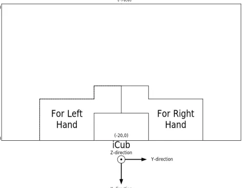
In Figure 3.4, the table which iCub will interact with objects on can be seen. Available areas that iCub can move his hands inside can be seen with boundaries. The commands that move iCub’s hands to outside this region are not allowed due to security reasons. This area is just shown for X and Y-directions, in Z-direction iCub has 28cm height to move his hands free.
(-20,0) iCub (-70,0) (-70,-44) (-20,-44) (-70, 44) (-20, 44) For Left
Hand For Right Hand
Y-direction
X-direction Z-direction
3.3
Perception Hardware
3.3.1
Visualeyez 3D Motion Tracking System
Visualeyez Motion Capture System is based on active optical technology which can track 3D motions with markers attached to the subject and is shown in Figure 3.5. It has support up to 512 markers with IDs with high accuracy and zero ID errors. In this work, this device was used for transformation of devices to iCub’s reference frame.
Figure 3.5: Visualeyez 3D Motion Tracking System1
3.3.2
iCub Eye Camera
iCub has RGB cameras in his eyes and can get 640 × 480 resolution images with 30fps. Camera was calibrated in order to eliminate fish-eye effects and find intrinsic parameters. We used the images obtained from eyes to perceive the features of the tools.
3.3.3
Kinect RGB-D Camera
Kinect, an RGB-D camera, shown in Figure 3.6, can give 640 × 480 resolution images at 30Hz.
Figure 3.6: Kinect RGB-D Camera2
We used two Kinects to sense the tools and objects by processing point clouds. Since each Kinect has its own reference frame, this reference frame was trans-formed into robot’s reference frame to have a common reference frame with iCub’s kinematics. Transformation was done using markers of the Visualeyez placed on Kinect. The pose and the coordinate point of iCub’s reference frame is known and using the markers from visualeyez, pose and the coordinate point of Kinect is also known in terms of iCub’s reference frame. After this process, rotation and translation matrices are computed to make the transformation.
After each Kinect was transformed into iCub’s reference frame, point clouds of each Kinect were combined in order to cover all sides of the tools and objects.
3.4
Construction of Tools
The tools are built of different colours of LEGO bricks. The handles of the tools are wrapped with a padding in order to ease grasping. In order to simplify grasping and segmentation of the tools from the table, a stand is prepared to
put the tool on. A tool consists of a main part(at least a holding region), left part(optional) and right part(optional).
3.5
Software Development Tools, Platforms and
Libraries
We used the following software tools and platforms to implement the perception learning and use of tools.
• Yet Another Robot Platform(YARP), a free and open software that consists of libraries, protocols and tools that keeps modules and also devices decoupled [19]. In this work, YARP middleware was used in order to control iCub’s devices and also to maintain communication with different modules. • Open Source Computer Vision Library(OpenCV), a library of func-tions for processing 2D images, was used for processing the image from iCub’s camera to compute the features of the tools [20].
• Point Cloud Library(PCL), an open project for 2D/3D image/point cloud processing, includes algorithms for filtering, registration, feature es-timation, reconstruction, segmentation and more [21]. In this work, PCL was used for 3D point cloud processing of tools and the objects.
• Weka Data Mining Software, a software tool consists of many data mining algorithms [22]. In this study, Weka was used for feature selection algorithms to reveal important tool and objects features.
• Support Vector Machines(LibSVM), supervised learning models with learning algorithms which is introduced Vapnik [23]. These learning models with associated learning algorithms help to analyze and recognize new input data. The main idea of SVM is creating a model that separates a set of points with a gap which is as wide as possible. When a newly seen datum is given as input to system, this input is mapped to the related point space
according to the model and depending on which side of the gap this mapped point is on, the input is labeled to that class.
Assume we have a training set as given below;
S = {(x1, y1), (x2, y2), ..., (xm, ym)|(xi, yi) ∈ Rn× {+1, −1}} (3.1)
The aim is to find a hyperplane as in the following form;
w · x + b = 0 (3.2)
to separate the instances where x is training samples, w is the coefficient and b is the constant. Vapnik showed that the optimal hyperplane is the one
which has the maximum d−+ d+ where d− denotes the shortest distance to
hyperplane from a negative instance and d+ denotes the shortest distance
to hyperplane from a positive instance. Using this fact, w and b are found by solving optimization problems. After this optimization problem, it turns out w can be expressed with some of the training samples as given below:
w =X
i
yiαixi (3.3)
xi’s are called are called support vectors and they lie on the margins of the
shortest instances. At the end of the SVM training algorithm αis and xis
are known. Using these, it is possible to classify an instance using:
class(x) = sgn(X
i
αihx, xii + b) (3.4)
Sometimes, training examples are not linearly separable, then this situation is solved using a mapping,
φ : Rn → F (3.5)
where in feature space F instances are linearly separable.
To classify an instance, lots of dot product calculations need to be done. In order to prevent expensive calculation kernel trick is used as given:
k(xi, xj) = φ(xi) · φ(xj) (3.6)
In this work, we used LibSVM, an integrated software for support vector machines that supports multi-class classification [24]. In LibSVM, there
variety of SVM types and kernel types, and also other parameters related to kernel and SVM type. To achieve a model that classifies well, user should find the good parameters.
Chapter 4
Perception
4.1
Tool Perception
The tools are perceived using visual images obtained from iCub cameras and point clouds obtained from Kinects. Tool features consist the features extracted from visual image and the features extracted from point clouds.
4.1.1
Tool Perception From Point Clouds
Tools are processed using combined point cloud from Kinects by applying the steps in the following Figure 4.1. At the end of these steps, tool features from Kinect RGB-D camera are obtained.
TABLETOP
FILTERING HOLD REGION DETECTION
MAIN, LEFT, RIGHT PART DETECTION
FEATURE EXTRACTION
Tool Processing From Kinect RGB-D Camera
• Tabletop Filtering: Using filters, point cloud of a tool is obtained by eliminating the points that belong table, environment, etcetera. The perceptual processing steps of a tool is shown in Figure 4.2. Figure 4.2(a) shows the sample original 3D world in front of the iCub. Figure 4.2(b) shows the sample point cloud of this 3D world from different perspective. Using passthrough filter, point cloud is filtered in x-dimension to capture the table in x dimension as it is shown in Figure 4.2(c). Then, point cloud is filtered in y and z dimensions in which samples are shown in Figure 4.2(d) and Figure 4.2(e) respectively.
(a) Original (b) 3D Point Cloud (c) x-Filtered
(d) y-Filtered (e) z-Filtered
Figure 4.2: First Steps of the Tool Processing with Kinect
At the end of these perceptual processing steps, point cloud of a tool is obtained as in Figure 4.2(e).
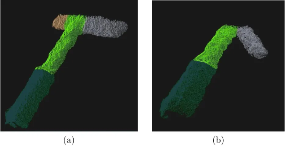
• Hold Region Detection: Using point cloud of the tool, grasping region of the tool is determined. As discussed in the previous chapter, grasping is a challenging behavior for iCub and we assumed that each tool has a handle of 4cm×4cm×13cm built from soft padding. Sample hold regions can be
seen in Figure 4.3(a) and Figure 4.3(b) with dark green colour. Target point for grasping is obtained by averaging points in hold region.
(a) (b)
Figure 4.3: Sample Hold Regions and Parts of the Tools
• Detection of Tool Parts: In this step, point cloud of a tool is divided
into 3 different point clouds as point cloud of left part, point cloud of main part and point cloud of right part in order to easily extract features specific to these parts. Towards the aim of detection, using the points of hold region, two line equations are found. One line to separate right part from main and left parts. The other equation to separate left part from main and right parts. These two line equation divide point cloud of the tool into 3 different point clouds. As a result, parts of the tool are obtained.
The sample point clouds of tool parts are shown in Figure 4.3(a) and Fig-ure 4.3(b) using different colours. Light and dark green colored parts are together create the main part of the tool.
• Feature Extraction: From each tool, the following 7 features(Figure 4.4) are compiled.
– main length of the tool (tool main length)
– horizontal length of the left part (tool left part to main) – horizontal length of the right part (tool right part to main)
– vertical below length of the left part (tool left part vertical down) – vertical upper length of the right part (tool right part vertical upper) – vertical below length of the right part (tool right part vertical down)
Figure 4.4: Kinect Tool Features
4.1.2
Tool Perception From Visual Images
The tool is also seen through the eye camera of iCub and the obtained image is processed to extract features using the following steps in Figure 4.5.
VISUAL IMAGE
ACQUISITION MORPHOLOGIC OPERATIONS SKELETONIZATION MAIN, LEFT, RIGHT PART DETECTION EXTRACTIONFEATURE
TOOL PROCESSING FROM EYE CAMERA
Figure 4.5: Tool Perception Steps Using Visual Image From Eye Camera
• Visual Image Acquisition: iCub looks at the tool and captures the visual image to start the image processing. A sample captured RGB image
of the tool can be seen in Figure 4.6(a). The captured RGB images are transformed into HSV(Hue, saturation, value) images as in Figure 4.6(b) in order to easily apply color segmentation to get the tool itself.
As stated in previous chapter, tools were constructed using LEGO with different colours in order to use colour segmentation on the image. Tools consist of 3 colours as pink colour for handle of the tool, blue and/or red colour LEGO for the remaining parts of the tools. Using the channel interval values of these colours in HSV image, the tool is partially segmented as shown in Figure 4.6(c).
• Morphological Operations: In order to eliminate irregular blanks and noise after color segmentation due to illuminate changes, dilation and ero-sion morphological operations are applied on segmented image. Before mor-phological operations by comparing size of all blobs in the image, possible small blobs are eliminated and tool segment is obtained as biggest blob. Dilation operation is used to fill the irregular blanks as in Figure 4.6(d) and erosion operation is used to eliminate noises as in Figure 4.6(e). After these operations, the tool segment is obtained.
• Skeletonization: The tool segment is skeletonized in order to generate a morphological representation of the tool. For this process, Zhang et al.’s thinning algorithm is used [25] on binary images. Algorithm traces on white pixels and at each pixel, a list of conditions are checked to decide whether the pixel will be removed or not. These conditions are related to neighbour pixels such as existence of a specific pattern, multiplication result of specific neighbour pixels etcetera. The process finishes when the points were traced but none of them were removed. The conditions which are checked by the algorithm and flowchart of the algorithm can be seen in Appendix A.1.1. At the end of the process, a fully connected skeleton of the tool is obtained. Sample skeletons can be seen in Figure 4.7.
(a) RGB Image (b) HSV Image (c) Color Segmentation
(d) Dilation (e) Erosion
Figure 4.6: Processing Steps Before the Skeletonization
Figure 4.7: Skeletonized Tools
• Detection of Tool Parts: In this step, parts of the tool are detected
by using special points on the skeleton in order to extract features. These special points are called “end points” and “middle points”. Middle points are the points where a part finishes and another part or parts start. End points are the points where a part finishes and does not continue even as another part. Sample end and middle points can be seen in Figure 4.8(a). These special points are determined by using a recursive function which
traces each point on the skeleton by looking its number of neighbours that are also points of the skeleton. If a point has only 1 neighbour then this point can be an end point, if it has 3 neighbours then it can be a middle point.
(a) Typical Case (b) Special Case
Figure 4.8: Red Dots Denote Middle Points, Blue Dots Denote End Points
In our study, a skeleton must have at least 2 and at most 3 end points, for middle points it must have at most 1 middle points. If there is no middle points left, this means our tool consists of only main part or main part plus left or right part. In order to find this, slopes are computed between intervals of skeleton pixels, if in any of the intervals, slope passes a specified threshold, then this means a new part is started. This special case can be seen in Figure 4.8(b) and Figure 4.9(c). Samples for all these parts are shown in Figure 4.9.
(a) (b) (c)
• Feature Extraction: In this step, using the end and middle points, tool features from eye camera are computed. This process includes trans-formation between iCub’s eye reference frame and iCub’s root frame. In order to find the corresponding 3D points of middle and end point pixels of the image, geometric distances between reference frame of the eye and the 3D points of middle and end points(these are obtained using Kinects) and pixel coordinates of these points in the image are used. Using the distances between 3D locations of end and middle points, following 5 features are computed:
– length of the left part (lengthOfLeft) – length of the right part (lengthOfRight) – length of the main part (lenghtOfMain) – existence of left part (existenceOfLeftPart) – existence of right part (existenceOfRightPart) These features can be seen in Figure 4.10.
4.2
Object Perception
iCub perceives the objects put on the table through the Kinects. The steps which are used to extract features from objects can be seen in the Figure 4.11. Objects can have different height, length and width and can be placed anywhere on the table.
TABLETOP
FILTERING EXTRACTIONFEATURE
OBJECT PROCESSING FROM KINECT RGB-D CAMERA
Figure 4.11: Object Perception Steps Using Point Cloud From Kinects
• Tabletop Filtering: We used the passthrough filter on each direction to segment the object from the background as can be seen in Figure 4.12.
Figure 4.12: Segmented Point Clouds From Sample Objects
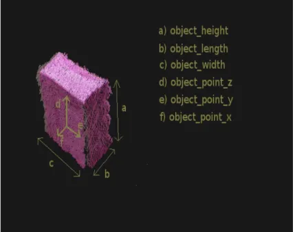
• Feature Extraction: Features are extracted from the segmented point clouds as shown in Figure 4.13. Extracted 6 features are:
– x dimension point of the object (object point x) – y dimension point of the object (object point y) – z dimension point of the object (object point z) – height of the object (object height)
– width of the object (object width) – length of the object (object length)
Figure 4.13: Features Obtained From Segmented Object From Kinect Range Data
Chapter 5
Behaviors
iCub interacts with the objects through a repertoire of behaviors. These behaviors can be classified into two groups as “behaviors with tools” and “behaviors without tools”. To apply these behaviors, iCub uses his hands. Therefore, which hand is used in an interaction is used as a feature.
5.1
Behaviors Without Tools
In the following behaviors, tools are not involved and these behaviors are either used to ease the perception or used to be prepared for behaviors with tools.
• Tuck-arms behavior used to ease perception and prevent occlusion on the table. Tuck arms position can be seen in Figure 5.1.
• Grasp behavior is used as a precursor to other behaviors. In order to grasp a tool, tactile sensors on palm and fingertips are used. Firstly, palm sensors are used to detect whether hand contacted to tool or not. Fingertip sensors are used to fully grasp the tool’s handle. A few examples of this grasp process are shown in Figure 5.2.
Figure 5.1: Tuck Arms Position
Figure 5.2: Grasping the Tool
5.2
Behaviors With Tools
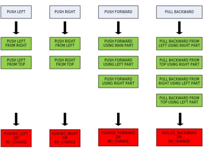
After grasping the tool, iCub interacts with objects using the tools in order to learn tool affordances. There are 11 different behaviors that can result with 5 different effects. These 11 different behaviors can be grouped into 4 main behavior types. These behaviors and effects can be seen in the Figure 5.3.
5.2.1
Effects of Tool Behaviors
The effects are determined by whether center of mass moved towards the re-lated way properly or not. These effect labels are given as supervised by the experimenter for the training phase.
PUSH LEFT PUSH RIGHT PUSH FORWARD PULL BACKWARD PUSH LEFT FROM RIGHT PUSH LEFT FROM TOP PUSH RIGHT FROM LEFT PUSH RIGHT FROM TOP PUSH FORWARD USING RIGHT PART
PUSH FORWARD USING MAIN PART PUSH FORWARD USING LEFT PART
PULL BACKWARD FROM RIGHT USING LEFT PART PULL BACKWARD FROM TOP USING LEFT PART PULL BACKWARD FROM LEFT USING RIGHT PART PULL BACKWARD FROM TOP USING RIGHT PART
PUSHED_LEFT OR NO_CHANGE PULLED_BACKWARD OR NO_CHANGE PUSHED_FORWARD OR NO_CHANGE PUSHED_RIGHT OR NO_CHANGE BEHAVIOR CATEGORIES TOOL BEHAVIORS POSSIBLE EFFECTS
Figure 5.3: Behavior Categories, Tool Behaviors and Their Possible Effects
• Pushed Left: If the center of mass of an object moved to left at the end of the interaction, it is labeled as pushed left.
• Pushed Right: If the center of mass of an object moved to right at the end of the interaction, it is labeled as pushed right.
• Pushed Forward: If the center of mass of an object moved away from the iCub at the end of the interaction, it is labeled as pushed forward.
• Pulled Backward: If the center of mass of an object moved closer to the iCub at the end of the interaction, it is labeled as pulled backward.
• No Change: If center of mass of an object stays still at the end of the interaction, it is labeled as no change.
5.2.2
Tool Behaviors
• Push Left From Right (PL-FR): iCub brings the tool from the right of the object by considering horizontal length of left part and by aligning the left down or upper part tip with object’s center and then moves his hand
horizontally towards the object as it can be seen in Figure 5.4. As a result, the effect can be no change or pushed left.
Figure 5.4: Push Left From Right
• Push Left From Top (PL-FT): iCub brings tool from top by considering vertical below length of left part and then lowers his hand and slides it to the left as shown in Figure 5.5. As a result, the effect can be no change or pushed left.
Figure 5.5: Push Left From Top
• Push Right From Left (PR-FL): This behavior is the symmetry of ”Push Left From Right”.
• Push Right From Top (PR-FT): This behavior is the symmetry of ”Push Left From Top”.
• Push Forward Using Main Part (PF-UM): iCub tries to push the given object to forward by using the main part of the tool as in Figure 5.6. As a result, the effect can be no change or pushed forward.
Figure 5.6: Push Forward Using Main Part
• Push Forward Using Left Part (PF-UL): iCub tries to push forward the object using the left part of the tool as it can be seen in Figure 5.7. The effect can be no change or pushed forward.
Figure 5.7: Push Forward Using Left Part
• Push Forward Using Right Part (PF-UR): This behavior is the sym-metry of ”Push Forward Using Left Part”.
• Pull Backward From Top Using Right Part (PB-FTUR): iCub brings the tool from top by considering the vertical below length of the right part then he lowers and moves his hand backwards in this behavior as in Figure 5.8. The effect can be no change or pulled backward.
Figure 5.8: Pull Backward From Top Using Right Part
• Pull Backward From Top Using Left Part (PB-FTUL): This behav-ior is the symmetry of ”Pull Backward From Top Using Right Part”. • Pull Backward From Right Using Left Part (PB-FRUL): iCub
brings the tool from right of the object as in ”Push Left From Right” behavior but considering the vertical below length of the left part. After-wards, he moves his hand towards the object at least horizontal length of the left part then he moves his hand backwards to pull the object back as in Figure 5.9. The effect can be no change or pulled backward.
Figure 5.9: Pull Backward From Right Using Left Part
• Pull Backward From Left Using Right Part (PB-FLUR): This be-havior is the symmetry of ”Pull Backward From Right Using Left Part”.
Chapter 6
Training of the System
Data collection system can be seen in the following diagram in Figure 6.1.
PLACE A NEW TOOL ON THE TABLE TOOL PROCESSING FROM KINECT RGB-D CAMERA TOOL PROCESSING FROM EYE CAMERA
OBJECT PROCESSING FROM KINECT RGB-D
CAMERA GRASP
TOOL
APPLY A BEHAVIOR AND LABEL THE INTERACTION
DATUM PLACE A NEW
OBJECT ON THE TABLE
OR
ADD INTERACTION DATUM INTO SPECIFIC BEHAVIOR
DATASET
Figure 6.1: Data Collection System Diagram
6.1
Dataset
6.1.1
Tools and Objects Used For Training
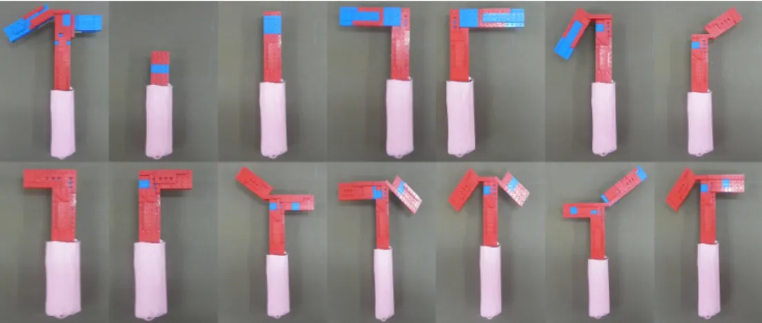
iCub used tools which have different lengths of main part, different lengths of left or/and right parts with different angles as can be seen in Figure 6.2.
Figure 6.2: Samples of Training Tools
After grasping the tool, iCub applies his interaction behaviors on objects with different shape and sizes as shown Figure 6.3.
Figure 6.3: Training Objects
6.2
Training Phase and Results
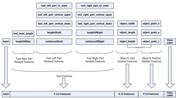
Table 6.1 shows the number of interactions which are collected using iCub. Col-lection of features that creates an interaction datum can be seen in Figure 6.4.
tool_main_length lengthOfMain tool_left_part_to_main hand tool_left_part_vertical_upper tool_left_part_vertical_down lengthOfLeft existenceOfLeft tool_right_part_to_main tool_right_part_vertical_upper tool_right_part_vertical_down lengthOfRight existenceOfRight object_point_x object_point_y object_point_z object_width object_length object_height dependent
Tool Main Part Related Features
Tool Left Part
Related Features Related FeaturesTool Right Part Related FeaturesObject s Size Object s Position Related Features
Class Label
hand
Tool Features
T (12 Features) O (3 Features) P (3 Features) LabelClass
Figure 6.4: All Features That Creates Interaction Datum
Table 6.1: Number of Interactions Gathered From Each Behavior
Behavior Number of
Interactions
Push Left (Bring From Right) 138
Push Left (Bring From Top) 152
Push Right (Bring From Left) 138
Push Right (Bring From Top) 152
Push Forward (Using Main Part) 240
Push Forward (Using Left Part) 115
Push Forward (Using Right Part) 115
Pull Backward (Using Left Part, Bring From Right) 99
Pull Backward (Using Right Part, Bring From Left) 99
Pull Backward (Using Left Part, Bring From Top) 114
Pull Backward (Using Right Part, Bring From Top) 114
In order to learn effective behavior models, collected interaction data should cover most of the possible situations for each behavior. As it can be seen in Fig-ure 6.4, an interaction datum consists of a hand featFig-ure, tool featFig-ures, object size features and object position features. When interaction data is being collected by an experimenter, it is not possible to cover all possible combination of feature
values because most of the features are numeric features which causes many com-bination between features. These different comcom-binations can result with different effects depending on a behavior. Therefore, interaction data in Table 6.1 are not enough to represent each of the behaviors. This reveals the need of having a big dataset that covers most of the possible combination of features.
6.2.1
Dataset Construction
As it was stated in previous part, in order to cover most of the possible com-bination of features, a big dataset should be constructed for each behavior. In this part, how dataset for a behavior is constructed will be explained. The whole dataset creation process can be seen in Figure 6.5. The steps for this process are: Creating Basis Feature Sets: We used the collected data from the robot’s interactions to create bigger behavior datasets.
First of all these 1476 interactions in Table 6.1 were combined into one dataset. This dataset was split into different datasets by grouping relevant features in the same dataset. As a result of grouping, we have tools’ main part related set(includes 2 features with 1476 entries), tools’ left part related set(includes 5 features with 1476 entries), tools’ right part related set(includes 5 features with 1476 entries) and lastly objects’ properties related set(includes 4 features with 1476 entries). Since hand, object point x and object point y features cannot be a part of tool creation or object selection phase because of this, they are not included in any of the set.
After feature sets were determined, among 1476 entries in each set, unique entries were selected by eliminating the duplicate entries. As a result of this selec-tion, number of unique entries in these basis feature sets were given in Table 6.2.
Table 6.2: Number of Unique Entries in Basis Sets
Set Number of Unique
Entries
Tool’s Main Length Related 19
Tool’s Left Part Related 108
Tool’s Right Part Related 108
Object’s Properties Related 76
The table indicates that among 1476 interactions, 19 tools with different main parts are used, 76 different objects are used and 108 different type of left and right parts are used.
Construction of An Interaction Datum: In this step using basis feature sets, an interaction datum is created. Using tool related basis feature sets, one can construct any kind of tool and can select any object using object related feature set. Remaining features should be selected by the user which are hand feature and position features those indicate where the object will be placed on the table. At the end of this selection from feature sets, an unlabeled interaction datum is obtained.
Labeling Constructed Interaction Datum: This step labels the unlabeled interaction datum with proper effect. In previous chapters, boundaries that iCub can move its hands in and movements of each behavior were shown and explained. According to these constraints and iCub’s kinematics, some conditions should be checked before the attempt of each behavior. These conditions determine whether iCub can accomplish the requested behavior on a shown object or not. If all conditions are satisfied, iCub is able to do the behavior on a given object with success. If a given interaction datum satisfies the conditions of the requested behavior then that instance is labeled as behavior specific effect, otherwise it is labeled as no change.
Creating Behavior Datasets Using Constructed Interaction Data: In this part using labeled interaction data, behavior datasets were created. For
this process, it is important to determine the number of interactions and deter-mine how many of these interactions should be labeled as behavior specific effect and how many of them will be labeled as no change. Since we have so many combinations with different tools, different objects and different positions, 10000 interactions were created for each behavior. Among these 10000 interactions, half of them belongs to behavior with left hand and the other half belongs to behavior with right hand. Among 5000 interactions, 1000 of them were labeled as behavior specific effect, 4000 of them were labeled as no change. The reason behind this ratio is this: In each behavior, there are not so many variety of behavior spe-cific effect situations. However, there may be many reasons for an instance to be labeled as no change. Therefore, this ratio is selected between number of behav-ior specific effect and no change labeled interactions. At the end, each behavbehav-ior has 10000 instances with 2000 behavior specific effect labels and 8000 no change labels. 14 76 I nt er ac tio ns W ith 1 9 Fe at ur es
Tool s Main Part Related Set (2 Features)
Object s Size Related Set (4 Features) Tool s Right Part
Related Set (5 Features) Tool s Left Part
Related Set (5 Features) Instance Creator Hand Object X Object Y Instance
Labeling This Specific Labeled Instance Needed?
Desired # of Labeled Instances Achieved? Add Labeled Instance to Dataset Yes No No Random Construction of An
Interaction From Basis Sets Constructed Instance Labeling Checking Whether # of Positive and Negative Labels is Reached or Not Yes, Return Set
6.2.2
Combination of Tool and Object Features
After datasets for each behavior were created, features are combined with each other in order to to reveal complex relations between different features specific to each behaviors. Because, it is not possible to infer relationships between features from the result of ReliefF feature selection if the behaviors are not simple.
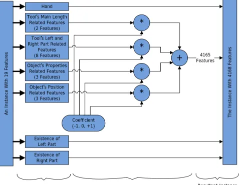
19 features in the dataset are combined in the following way. First of all, 19 features are split into sensible parts which are similar to basis feature sets. For this combination process, 19 features split into 4 groups. These are; a group which consists tool main part related features (2 features), a group consists tool’s left and right part related features (8 features), a group consists of object properties (3 features) and lastly a group that consists position features of the object (3 features). Hand, existenceOfLeftPart and existenceOfRightPart features were not involved in the groups since they are nominal features.
Each of the features in these four groups are combined by having an integer coefficient(-1,0,+1) in order with all possible combinations. At the end of the process, the dataset ends up with 4168 features. The process of combination of core features can be seen in the Figure 6.6.
6.2.3
Feature Selection and Feature Elimination on
Com-bined Dataset
Feature Ranking: In this part, 4168 features are ranked according to their con-tributions to separation of the labels. Towards this end, ReliefF feature selection method is applied on each behavior datasets as explained in Appendix A.2. The result of ReliefF method is a ranked features of dataset.
Feature Elimination: Among the ranked 4168 ranked features, unnecessary features are eliminated from the feature set. In order to do this, following way is used: “If a combined feature will remain in the dataset, it must be ranked better than its subset of combined features”. Assume the following small sample set in
An I ns ta nc e W ith 1 9 Fe at ur es Th e In st an ce W ith 4 16 8 Fe at ur es Hand Existence of Left Part Existence of Right Part Tool s Main Length
Related Features (2 Features) Tool s Left and Right Part Related
Features (8 Features) Object s Properties Related Features (3 Features) Object s Position Related Features (3 Features) Coefficient {-1, 0, +1} * * * * + 4165 Features
Split Features into Sensible Groups For Combination
Feature Kernel Which Creates Every Possible Combination of Input Features
Resultant Instance With All These
Features
Figure 6.6: Feature Combination Process
Table 6.3:
Table 6.3: A Sample Ranked Feature Set Before Elimination
Ranking Feature Name
1 +object width
2 +tool main length+object point x
3 +object width-object point y
4 +tool main length-tool left part vertical down+object point x
5 -object point y
6 -tool left part vertical down+object point x
7 +object point x
8 -tool left part vertical down
9 +tool main length-tool left part vertical down
Table 6.3 shows a sample dataset of features before the process of elimination. Ranked 1,5,7,8 and 10 features will remain in set because they are core features.
For the 2nd ranked feature, it is ranked higher than its subsets which are 7th
and 10th. So, the 2nd feature will remain in the set. 3rd feature will not be
included since one of its subset feature is ranked 1st which is higher. This means
+object width feature is ranked very high but its combination with -object point y feature lowers its rank. Therefore, it will be removed from the set.
A similar situation is valid for +tool main length-tool left part vertical down +object point x feature, since this feature is a combination of 3 features, we
should also look its 2-featured subsets. Since one of its subsets which is
+tool main length+object point x is ranked higher, this feature will also be
re-moved. 6th ranked feature is ranked higher than its subset so it will remain but
9th feature will not be able to remain in the set since one of its subsets is ranked
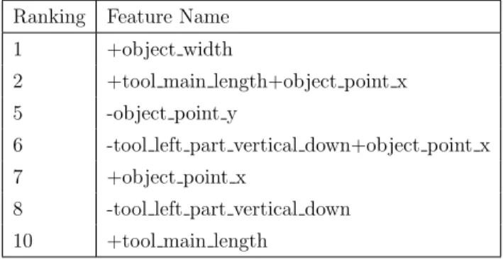
higher than itself. The resultant set after elimination can be seen in Table- 6.4 Table 6.4: The Sample Ranked Feature Set After Elimination
Ranking Feature Name 1 +object width
2 +tool main length+object point x 5 -object point y
6 -tool left part vertical down+object point x 7 +object point x
8 -tool left part vertical down 10 +tool main length
6.2.4
Performance of Each Behaviors After Feature
Selec-tion and EliminaSelec-tion
After the selection and elimination process, the following number of features are remained in behavior datasets in Table 6.5.
Number of features for each behavior in Table 6.5 do not represent the behaviors in a best way. In order to find the best number of features that represents the behavior, support vector machine performances are examined at each number
![Figure 1.1: Developmental Stages of Tool Use (Taken from Guerin et al. [1])](https://thumb-eu.123doks.com/thumbv2/9libnet/5942268.123783/18.918.215.749.480.756/figure-developmental-stages-tool-use-taken-guerin-et.webp)