Effect of tool path strategies and cooling conditions in pocket machining of AZ91 magnesium alloy
7
0
0
Tam metin
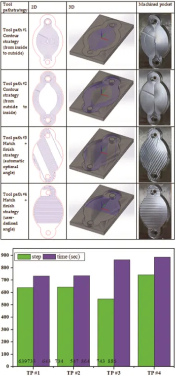
(2) 140. INDIAN J. CHEM. TECHNOL., MARCH 2019. 0.13% Mn, 0.002% Ni, 0.1% Si, 0.35-1%Zn and 90% Mg was used throughout the experimental study. 12 samples were prepared from 900×600×10 mm block material in dimensions of 170×100×10 mm. In the experimental study, 5 mm diameter, 45° helix angle and 3-flute solid carbide end mills were used (Fig. 1). As seen from the figure, the size of the cutting edges of the end mill is not equal. A new end mills were employed for each pocket milling condition to eliminate any possible tool wear effects on the milling force, temperature, tool wear, and surface topography results. Pocket machining experiments were performed on a vertical machining center (Quaser MV 154 C). All milling tests were conducted dry, coolant and air blast condition. The coolant was obtained by mixing the boron oil with water that is a ratio of 1:25 to the cutting zone. Air blast delivered through a nozzle was directed at the milling region for all milling experiments performed. Milling force measurements were carried out using a three-component piezoelectric dynamometer (Kistler 9257B). The temperature was measured using an infrared measuring system. The flank wear of tool small and medium edge was measured using a digital microscope (Keyence VHX-900F). The surface topography of the machined pockets was done with Zygo ZeGAGE optical profilometer. Experiments were performed with fixed cutting parameters: 110 m/min cutting speed and 0.195 mm/rev feed rate, 2 mm axial depth of cut (total 8 mm with 4 equal passes). The effect of employing tool path strategies and cooling conditions when milling AZ91 magnesium alloy was investigated in relation to machining time, milling step, milling force,. Fig. 1 — End mill used in pocket machining process.. cutting temperature, tool wear, and surface quality (topography and surface roughness). The geometry used in the experimental study, experimental set-up, force, temperature, surface topography and tool wear measurement are given in Fig. 2. Two different tool path strategies generally used in industry when machining are hatch and contour pocket milling. Four different pocket milling strategies were selected in this study: Tool path #1 contour strategy (from inside to outside), Tool path #2 contour strategy (from outside to inside), Tool path #3 hatch+finish strategy (automatic optimal angle) and Tool path #4 hatch+finish strategy (user-defined angle). Table 1 illustrates the tool path strategies direction, its simulation (2D and 3D) and machined pocket. Tool path #1 (TP #1): The cutting tool completes the defined geometry by machined it from inside to outside. Tool path #2 (TP #2): The cutting tool completes the defined geometry by machined it from outside to inside. Tool path #3 (TP #3): This strategy enables to machine the pocket in a linear pattern. The software automatically calculates the optimal angle of hatching to expedite the milling. The tool path always follows the length of the pocket no matter what angle the pocket is facing. Tool path #4 (TP#4): This technology enables to determine the angle of the tool path11. Results and discussions The step and machining time required to machining the designed pocket geometry with CAM software simulation using four different tool path strategies was determined (Fig. 3). As seen from the Fig. 3, the designed geometry, which was with the use of Tool. Fig. 2 — The geometry used in the experimental study, experimental set-up and measuring instruments..
(3) BASMACI et al.: POCKET MACHINING OF AZ91 MAGNESIUM ALLOY. Table 1 — Tool path strategiesemployed in these experiments.. 141. strategy is derived from Tool path # 4. The designed geometry uses at least steps (547) with Tool path #3 strategies while Tool path #4 is machined with up to step 743. Using Tool path #1 and Tool path #2, the designed pocket has machined in almost equal steps. Cutting force analysis in pocket machining. Fig. 3 — Effect of tool path strategies on step and machiningtime.. path #1 and Tool path #2 tool paths, was milled at almost equal times and in shorter steps (~ 130-152 sec) than the other two tool path strategies. The contour tool path strategy (Tool path #1 and Tool path #2) used in the study has almost no effect on the machining time from inside to outside or from the outside to the inside. The longest-time pocket milling. Cutting force is a significant result during machining, and it has a direct effect on a generation of heat, power consumption, tool wear or failure, surface quality and accuracy of the work piece12-13. The milling forces at X, Y and Z directions were measured online. However, the milling force in the Z direction was not taken into account because of the small value. The X and Y direction Fx and Fy forces were compared only. Figure 2 shows the milling force components. The designed geometry was cut to 4 equal (2 * 4 = 8 mm) axial depth of cut. Cutting forces were measured in the first period. The change of cutting force under different tool path strategy is shown in Fig. 4. The milling forces obtained from the dynamometer for 1 period are given here. In Fig. 4, only graphs are generated in dry conditions, as similar trend graphs are obtained in tests performed with dry, coolant and air blast. In addition, the milling force graph is zoomed and the milling forces generated when the end mill is engaged in a turn. In the tests performed in different tool paths and coolant conditions, the maximum values of the force values measured from the dynamometer were taken and Fig. 5 was formed. As seen from the Figure, the maximum milling forces (both Fx and Fy) are formed in dry cutting conditions in all tool paths, while the least milling forces are formed in coolant condition. This is similar to the literature. The end mill– magnesium alloy interface absences lubrication and cooling due toa high friction coefficient. Coolant machining achieves significantly lower component and resultant forces than dry machining13. When the cutting forces in X and Y directions are compared in terms of tool paths, very close milling force values are obtained in TP # 1 and TP #2. It is observed that when pocket milling with TP #4, the highest cutting force is observed followed by TP #3, TP #1, and TP #2, respectively. It is clear that TP#1 or TP #2 tool path must be selected and coolant should be used to minimize the cutting forces occurring at the cutting. Since the comparison between strategies takes place in the same conditions, tool-chip contact area is one of the reasons for cutting force differences between different strategies14..
(4) INDIAN J. CHEM. TECHNOL., MARCH 2019. 142. Fig. 4 — Schematic of milling force.. Fig 5 — Comparison of cutting forces. Temperature measurement. Temperature measurements were made at the final cutting depth where the cutting tool temperature reached the highest value. During the machining process, temperature measurements were made by infrared digital thermometer by the cutting tool that was taken maximum temperature which is maximum value (Fig. 6). The highest temperature is occurred in. dry cutting conditions, while the lowest temperature is occurred in coolant condition (32% less than dry cutting conditions). The highest temperature is occurred by the usage of TP #3 strategy, while the lowest temperature is occurred by the TP #4 strategy. More heat is generated that other strategies because the TP #3 strategy processes the designed geometry with fewer steps. The temperature values of the other tool paths were measured close to each other. The high machining heat will accelerate the wear of the end mill and reduce its life, thus, influencing the machined quality of the workpiece. Cutting force can reflect not only the milling state in processing but also the lubrication performances of coolant13. Evaluation of roughness of machined surfaces. The surface roughness is an essential factor for workpiece surface quality evaluation and, it determines surface smoothness. Low surface roughness reflects high surface smoothness. Surface roughness can influence fatigue strength, contact stiffness, and corrosion resistance of workpiece and significantly improve cooperation. Moreover, surface roughness.
(5) BASMACI et al.: POCKET MACHINING OF AZ91 MAGNESIUM ALLOY. influences the service life and reliability of machinery products13. The AZ91 magnesium alloy is milled with different tool paths, cooling strategies, and the topography of the machined surfaces is observed (Fig. 7). 5.5X magnification lens is used. Fig. 6 — Comparison of temperature.. 143. a1500×1500 µm in the machined surface was examined. For each tool path strategies and cooling conditions, numeric values are obtained and Fig. 8 is formed. Average roughness (Ra) and root mean square roughness (Rq) are the most widely used surface parameters in the industry15. Ra is the arithmetic mean of the absolute departures of the roughness profile from the mean line. Rq is the square root of the average of the square of the deviation of the mean line16. The highest Ra and Rq values were obtained under dry cutting conditions, while the minimum Ra and Rq values were obtained in the process with coolant. The highest quality surface is obtained by using the Tool path #4 strategy to machining the designed geometry, while the worst surface is obtained by machining with Tool path #3 strategy. The poor surface quality was caused by abrupt tool conditions. A sudden increasing in the chip volume resulted in excessive vibrations lead to raised cutting forces17.. Fig. 7 — Comparison of surface topography..
(6) 144. INDIAN J. CHEM. TECHNOL., MARCH 2019 Tool wear. Fig. 8 — Ra and Rq under different tool path strategy and cooling conditions.. The end mill used in the experiments has 3 cutting edges and each cutting edge has a different length (Fig. 1). The flank wear measurement on the cutting tool was carried out with a digital microscope (Fig. 2). There was not much wear on the long cutting edge of the end mill. For this reason, wear at short and medium length cutting edges were measured. Figure 9 shows the wear photographs of the medium length cutting edge. Figure 10 shows the graph created from the measured wear values. A certain amount of flank wear on the cutting tools has been observed during pocket milling tests. All of the tool paths used, the highest wear occurred in dry milling conditions, while the least wear occurred in the process with the coolant. Machining in dry. Fig. 9 — Tool wear under different tool path strategy and cooling conditions..
(7) BASMACI et al.: POCKET MACHINING OF AZ91 MAGNESIUM ALLOY. . . . Fig. 10 — flank wear under different tool path strategy and cooling conditions.. conditions has increased the wear to 3.5 times. The formation of more tool wear in dry conditions believed to be the main reason for the higher cutting forces, cutting temperature, and friction18. TP#2 strategy shows the highest tool wear of 118 µm, followed by TP#3 of 80 µm, followed by TP#1 of 60 µm, and finally, TP#4 of 34 µm in dry condition. Conclusion The effect of employing different tool path strategies on a step, machining time, milling force, temperature, surface quality, and tool wear when pocket milling of magnesium alloy was investigated. The designed geometry is machined in almost equal time and in equal steps using Tool path #1 and Tool Path #2 tool path strategies. Using the Tool path #4 strategy, the geometry is machined in more machining time and more steps than any other tool path strategies. Using the Tool path #1 and Tool path #2 strategies, very close cutting forces (Fx and Fy) were obtained. It is observed that when pocket milling with Tool path #4, the highest cutting force is observed followed by Tool path #3, Tool path #1, and Tool path #2, respectively. The maximum temperature is formed by the use of the Tool Path #3 strategy, while the lowest temperature is formed by the Tool path #4 strategy. In Tool path #1 and Tool path #2, close temperature values were measured.. 145. The highest surface is obtained by machining the with the Tool path #4 strategy, while the worst surface is derived from the Tool path #3 strategy. In Tool path #1 and Tool path #2, close surface values were measured. Tool path #2 strategies shows the highest tool wear of 118 µm, followed by Tool path #3 of 80 µm, followed by Tool path #1 of 60 µm, and finally, Tool path #4 of 34 µm in dry condition. In conclusion, where the least worn end mill, minimum temperature, and best surface quality were concerned, Tool path #4 strategy was the most favorable.. Acknowledgements This work was supported by Commission of Scientific Research Projects of Mehmet Akif Ersoy University (Project No. 0438-YL-17). References 1 2 3 4 5 6 7 8 9 10 11 12 13 14 15 16 17 18. Tao J Q, Zhang Y P, Fan F Y, & Chen Q, Defence Technology, 9 (2013) 146. Watanabe H, Yamaguchi M, Takigawa Y, & Higashi K, Mater Trans, 49 (2008) 1262. Dinesh S, Senthilkumar V, Asokan P & Arulkirubakaran D, Mater Des, 87 (2015) 1030. Sunil B R, Ganesh K V, Pavan P, Vadapalli G, Swarnalatha C, Swapna P, Bindukumar P, Pradeep Kumar G Reddy, J Magnesium Alloys, 4 (2016) 15. Mohd Hadzley A B, Siti Sarah A, Izamshah R, & Nurul Fatin M R , Appl Mech Mater, 699 (2015) 64. Danis I, Wojtowicz N, Monies F, Lamesle P & Lagarrigue P, Procedia Eng, 63 (2013) 36. Monies F, Danis I, Bes C, Cafieri S & Mongeau M, Int J Adv Man Technol, 92 (2017) 3883. Monies F, Danis I, Lagarrigue P, Gilles P & Rubio W, Int J Adv Man Technol, 89 (2017) 45. Buldum B, Eşme U, Kemal Külekci M, Şik A & Kazançoğlu Y, Mater Testing, 54 (2012) 779. Buldum B B, Şık A, Akdağlı A, Biçer M B, Aldaş K & Özkul İ, Mater Testing, 59 (2017) 916. SolidCAM software, Solid CAM imachining – The Revolution in CAM. Liu M, Zhang Z, Zhou Z, Peng S & Tan Y, Mechatronics, 31 (2015) 22. Yin Q, Li C, Zhang Y, Yang M, Jia D, Hou Y & Dong L, Int J Adv Man Technol, 97 (2018) 1. Shajari S, Sadeghi M H & Hassanpour H, Sci World J, 14 (2014) 1. Lou M S, Chen J C & Li C M, J Industrial Technol 15 (1998) 1. Frank J F & Chmielewski R, J Food Prot, 64 (2001) 1178. Toh C K, Mater Des, 27 (2006) 107. Koklu U & Basmaci G, Metals, 7 (2017) 426..
(8)
Şekil


+2

Benzer Belgeler
Üniversiteler bilimsel özerkliğe ve kamu tüzel kişiliğine sahip olarak yüksek düzeyde eğitim-öğretim, bilimsel araştırma, yayın ve danışmanlık yapmak üzere kurulan
Üniversiteler bilimsel özerkliğe ve kamu tüzel kişiliğine sahip olarak yüksek düzeyde eğitim- öğretim, bilimsel araştırma, yayın ve danışmanlık yapmak
• Üniversite öğrencilerine ve topluma, iletişim ve bilgi teknolojilerine dayalı uzaktan eğitim yoluyla sunduğu tüm dersler, kurslar, seminerler, konferanslar ve benzeri
paylaşımı ve ortak kullanımı, çalışma sürecinin bir parçası olarak örtük bilginin açığa çıkarılması, bilgi varlığının ölçülmesi, kurumsal bilgi kültürünün
MADDE 31- (1) Her öğrenci topluluğu, bir akademik yıl içinde gerçekleştirmek istediği etkinlik planını ve buna ilişkin bütçe talebini, topluluk yönetim kurulu ve
C.J.Andersen’in sekiz etüt kitabında yer alan toplam 188 etüt, kullanılan dil teknikleri yönünden incelenmiş, diğer teknik ve müzikal konular ele
İngiliz Afrikan Kraliyet Şirketi tekel olarak başladığı Afrika ticaretinde bu yetkisini diğer İngiliz iş insanları ve şirketleri ile paylaşmasıyla birlikte çok daha fazla
(3) Lisansüstü dersler, ilgili EABD/EASD başkanlığının önerisi ve EYK onayı ile diğer yükseköğretim kurumlarında verilmekte olan derslerden yüksek lisans
