Numerical Characterization of In Vivo Wireless
Communication Channels
A. Fatih Demir
1, Qammer H. Abbasi
2, Z. Esad Ankarali
1, Erchin Serpedin
2, Huseyin Arslan
1,3 1Department of Electrical Engineering, University of South Florida, Tampa FL, USA
2Department of Electrical and Computer Engineering, Texas A&M University, USA/Qatar
3Department of Electrical and Electronics Engineering, Istanbul Medipol University, Istanbul, Turkey
Email: {afdemir, zekeriyya}@mail.usf.edu, [email protected], [email protected], [email protected]
Abstract — In this paper, we numerically investigated the in
vivo wireless communication channel for human male torso at 915 MHz. Results show that in vivo channel is different than the classical communication channel and location dependency is very critical for link budget calculations. A statistical path loss model based on angle, depth and body region is introduced for near and far field regions. Furthermore, multipath characteristics are investigated using a power delay profile as well.
Index Terms — Body area networks, channel model, in vivo propagation, medical implants, wave propagation.
I. INTRODUCTION
Technological advances in biomedical engineering have increased quality of life and life expectancy. Early diagnosis of diseases is crucial but the cost of healthcare is not affordable for everyone. Wireless in vivo sensors and actuators offer cost efficient solution for this problem providing a reliable continuous monitoring system of patient’s vital signs. Meanwhile, deployment of these devices reduces hospital visits and invasiveness of surgeries [1].
Accurate channel models are important to optimize physical layer communication system in terms of power and spectral efficiency. Although on body wireless communication channel models are well studied [2], there is relatively less work found in literature for in vivo wireless communication channels. In vivo channel’s characteristics are different than the classical communication channel’s characteristics due to electromagnetic wave propagation through various tissues and organs, which have different electrical properties. The liquid nature of human body structure causes RF attenuation, whereas, the skeletal structure causes wave diffraction and refraction with respect to corresponding frequency [3].
There is a tremendous ongoing research to characterize in vivo wireless communication channel in recent years [3]-[8]. Sani et al. [4] demonstrated that radiation characteristics of wireless implants are subject specific and strongly related to the location of the sensor. Ketterl at al. [5] showed that even slight changes in position of the external receive antenna at a fixed distance from the internal antenna causes significant variations in received signal strength. Therefore channel models without considering the relevant body region may not be reliable. In [6], it was found that there is no direct co-relation between near and far fields due to presence of reactive
fields in the near region of ingested sources. Moreover, Alomainy et al. [7] revealed that electric field attenuation is more dependent on distance rather than frequency because of near field effect inside the empty stomach. These results show that both near and far fields need to be investigated to obtain sufficient information about in vivo channel characteristics.
This paper presents a detailed numerical characterization (by performing approximately 1500 simulations) of in vivo wireless communication channel for human male torso by considering location dependency (angle, depth and body region) for both near and far field regions. Based on these parameters a statistical formula for path loss is defined and multipath characteristics of the channel are examined through power delay profile.
II. SIMULATIONSETUP
Analytical methods are infeasible and require extreme simplifications for radio propagation investigation inside the human body, hence numerical methods are used usually [3] – [8]. In this paper, we used ANSYS HFSS 15.0, which is a full wave electromagnetic field simulator based on Finite Element Method (FEM). ANSYS also provides a detailed human body model of adult male.
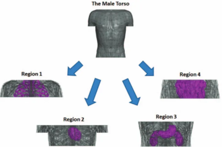
Fig. 1: Regions 1 to 4 represent the body areas of shoulders to heart (including first six rib bones), heart, stomach - kidneys and intestine respectively.
Due to inhomogeneous characteristics of human body, investigation of wireless communication channel without taking into account the relevant body area would be insufficient. Hence, torso area is divided into 4 subregions considering the major internal organs like heart, stomach, kidneys and intestine as shown in Fig. 1. Measurements are taken for each subregion by rotating both receiver (ex vivo) and transmitter antennas (in vivo) around the body in X-Y plane with 22.5° angle increments as shown in Fig. 2. For a fixed position of receiver antenna, transmitter antenna is placed at 10 different depth values (10mm to 100mm). It is important to point out that antennas are not rotating in a circular path around the human body. In each angle, a new coordinate system is defined exactly on the body surface and both antennas are placed with respect to this new coordinate system. Moreover, antennas are placed in the same orientation that there is no polarization loss in the results.
Omni-directional dipole antennas at 915 MHz (ISM band) are used to take measurements in the simulations. Dipole antenna size is proportional to the wavelength, which changes with respect to both frequency and permittivity. Thus, in vivo antennas typically have geometry smaller than in the free space, which causes very low transmission efficiency. However, the characteristics of the biological tissues make small antennas to be an efficient radiator [3]. In this study, operation frequency is fixed but permittivity value of the environment is variable. Therefore, average permittivity value of each body region is estimated and then appropriate antenna size is selected for maximum power delivery. Estimated average permittivity values of Region 1 to 4 are 16, 16, 27 and 29 respectively. Near and far field scenarios are investigated by placing the receiver antenna (ex vivo) 5 cm and 30 cm away from the body surface, respectively. Antenna locations with high return loss (i.e. >-7dB) skipped from the data.
III. RADIO CHANNEL CHARACTERIZATION
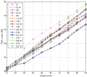
We investigated angle, depth and body region dependent characteristic of path loss, which is a measure of average signal power attenuation, for near and far field regions. The signal propagates through different organs and tissues for various antenna locations that path loss changes significantly even for the same depth value from body surface. Fig. 3 shows results of near field path loss for each angle, where linear averages of four region’s path loss values are calculated for each depth and angle (Far field figures are not included in the paper due to limited space). It is observed that 0o has the
highest path loss, whereas symmetric locations, 112.5o and
247.5o have the lowest attenuation. The number of scattering
objects (random variables) increases as the in vivo antenna goes deeper. Therefore, variance of each depth’s path loss values among 16 angles increases as the increase in depth due to summation of random variables as can be seen in Fig. 3.
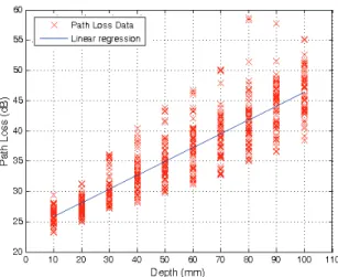
In addition, the path loss values are fitted into a statistical formula using least squares linear regression model. In the literature, path loss is commonly modeled with a logarithmic function [1], [4], [7], [8], however, we observed that a linear function fits better since convergence of mean square error is smaller when the gradient descent algorithm is applied. Path loss is modeled as a function of depth by the following linear equation in dB:
PL (d) = PL0 + m (d / d0) + S (d d0)
where d is the depth distance from body surface in millimeters, d0 is the reference depth distance (i.e. 10mm),
PL0 is the intersection term in dB, m is the decay rate of
received power and S is the random scattering parameter in dB, which is a normally distributed random variable with zero mean and variance ı. This random scatter caused by different body materials and the antenna gain in different directions [8].
Fig. 2: 16 (angles) x 10 (depth) x 2 (near-far regions) x 4(subregions) = 1280 simulations in total for path loss.
Fitted statistical parameters for the model are summarized in Table 1. There is 30% difference in decay rate of received power (m) between Region 2 and Region 3. Path loss at Region 1 and Region 4 show more deviation around the mean than other two regions. Angle values are combined into 4 sides to show angle dependency of the channel in a more convenient way. Posterior body has the least decay rate and the variation in path loss, whereas anterior body has the highest values. Additionally, path loss decay rate is higher in near field measurements than far field for all regions and sides as expected. Multipath characteristics of the channel can be investigated by power delay profile (Fig. 5) and greater dispersion is observed in the sides than anterior or posterior body. These variations based on angle, depth, and body region are required to be considered for link budget calculations not to harm biological tissues and to provide power efficiency.
IV. CONCLUSION
We presented location dependent characteristics of in vivo wireless communication channel using a full wave numerical RF simulator for both near and far field regions. A statistical path loss formula based on angle, depth, and body region
parameters is introduced and multipath characteristics are investigated for various antenna locations. These results emphasize the difference of in vivo wireless communication channels than the classical channels and show that in vivo wireless communication systems need to be designed carefully with regard to location of operation.
ACKNOWLEDGEMENT
This publication was made possible by NPRP grant # NPRP 6 - 415 - 3 - 111 from the Qatar National Research Fund (a member of Qatar Foundation). The statements made herein are solely the responsibility of the authors.
REFERENCES
[1] S. Movassaghi, M. Abolhasan, J. Lipman, D. Smith, and A. Jamalipour, “Wireless body area networks: A survey,” in IEEE Communications Surveys & Tutorials, vol. 9, 2014, pp. 1–29. [2] IEEE P802.15 Working Group for Wireless Personal Area
Networks (WPANs), “Channel Model for Body Area Network (BAN).”
[3] K. Y. Yazdandoost and R. Kohno, “Wireless Communications for Body Implanted Medical Device,” in 2007 Asia-Pacific Microwave Conference, 2007, pp. 1–4.
[4] A. Sani, Alomainy, and Y. Hao, “Numerical characterization and link budget evaluation of wireless implants considering different digital human phantoms”, IEEE Trans. Microw. Theory Tech., vol. 57, no. 10, pp. 2605–2613, Oct. 2009. [5] T. P. Ketterl, E. Arrobo, P. Alphan Sahin, T. J. Tillman, H.
Arslan, and R. D. Gitlin, “In vivo wireless communication channel,” in IEEE 13th Annual, Wireless and Microwave Technology Conference (WAMICON), 2012.
[6] L. C. Chiwra, P. A. Hammond, S. Roy, and D. R. S. Cumming, “Electromagnetic radiation from ingested sources in the human intestine between 150 MHz and 1.2 GHz,” IEEE Trans. Biomed. Eng., vol. 50, no. 4, pp. 484–492, Apr. 2003
[7] A. Alomainy and Y. Hao, “Modeling and characterization of biotele- metric radio channel from ingested implants considering the organ contents,” IEEE Trans. Antennas Propag., vol. 57, no. 4, pp. 999–1005, Apr. 2009
[8] K. Sayrafian-Pour, W.-B. Yang, J. Hagedorn, J. Terrill, K. Yekeh Yazdandoost, and K. Hamaguchi, “Channel Models for Medical Implant Communication,” Int. J. Wirel. Inf. Networks, vol. 17, no. 3–4, pp. 105–112, Dec. 2010.
Fig. 4: Path loss versus distance for near field setup. Fig. 5: Power delay profile for each side