IMPACT OF INTRODUCING SEMI-RIGID
MOMENT FRAMES ON SEISMIC RESPONSE OF
BRACED FRAMES
MAHMOUD FAYTAROUNI1, ONUR SEKER2, BULENT AKBAS3, and JAY SHEN1 1
Dept of Civil, Construction and Environmental Engineering, Iowa State University, Ames, USA
2
Dept of Civil Engineering, MEF University, Istanbul, Turkey
3
Dept of Civil Engineering, Gebze Technical University, Kocaeli, Turkey
Maximum seismic inelastic drift demand in a steel building with braced frames as primary seismic-force-resisting (SFR) system tends to concentrate in few stories without considering inherent participation of designed gravity-force-resisting (GFR) system in actual structural stiffness and strength. The influence of GFR system on stiffness and strength can be taken into account by considering the composite action in beam-to-column shear connections that exist in modern steel building construction to form actual semi-rigid moment-resisting frames. Therefore, modeling semi-rigid moment frames as an equivalent to the GFR system in braced frame buildings could be utilized as a representative to the strength provided by gravity frames. This paper presents a seismic evaluation of a six-story chevron braced frame, with and without semi-rigid moment frame. Four different cases are investigated under a set of ground motions and results are discussed in terms of story drift distribution along the height. The results pointed out that the current findings lay a foundation to conduct further investigation on the seismic performance of braced frames as designed SFR system together with GFR system.
Keywords: Braced frame, Semi-rigid moment frame, Pushover analysis, Non-linear
time history analysis, Seismic drift demand.
1 INTRODUCTION
Concentrically braced frames (CBFs) are considered among the most efficient lateral force resisting systems that absorb energy through buckling and yielding of braces. Their high lateral stiffness and strength placed them among the most commonly used structural systems for resisting earthquakes. Despite the beneficial features that this system exhibit, it presents some major shortcomings in the seismic performance. When braces buckle at any given story level, the post-buckling stiffness and strength of that story drops significantly causing a rapid increase in story drift demand, which leads to an unanticipated ductility demand concentration on braces. Eventually, this drift concentration in isolated stories give rise to brace fracture while upper stories moves similar to a rigid body without being affected from the inelastic deformation demand. In addition, recent research (Uriz 2008) has also found that the concentration of post-buckling deformations in a single story induces significant flexural demand on columns that may lead to a column fracture. More recently, a study by Shen et al. (2017) have also found that braces in CBFs are very likely to fracture prior to the design story drift due to large ductility
demand on braces that have been mutually influenced by the inelastic deformation in beams and columns. In view of these shortcomings, considerable attempts have been devoted to obtain a more desirable and uniform inelastic deformation distribution either by providing a more redundant and ductile backup system like moment resisting frames (Goel 1992) or by controlling buckling in braces (Seker et al. 2017) or both (Kiggins and Uang 2006).
Further, the inherent participation of GFR system can contribute significantly to the lateral stiffness and strength of the steel braced building, and capable of limiting the drift concentration subsequent to brace buckling. In fact, the impact of GFR system on the stiffness and strength can be taken into account by considering the composite action in beam-to-column shear connections that exist in modern steel building construction to form actual semi-rigid moment-resisting frames. Majority of existing studies consider the effect of GFR system by modeling the gravity columns only. Nevertheless, very few studies can be found in the literature investigating the impact of gravity beams with shear tab connections together with gravity columns on the seismic performance of CBFs, predominately when they act compositely with the concrete floor system. Although no study has been found on special CBFs, studies sponsored by AISC on non-ductile CBF buildings (i.e., Shen et al. 2017 and Wen et al. 2017) have found that beam-to-column shear connections are capable of resisting substantial moments, about 30% to 50% of the beam plastic moment. Thus, the focus herein is on the seismic behavior of braced frames coupled with semi-rigid moment frames, employed as an equivalent to the strength provided by the GFR system in steel braced building. Accordingly, six-story braced frame with chevron configuration was evaluated to study the impact of semi-rigid moment frames, referred to as MFs hereafter.
2 BUILDING DESCRIPTION
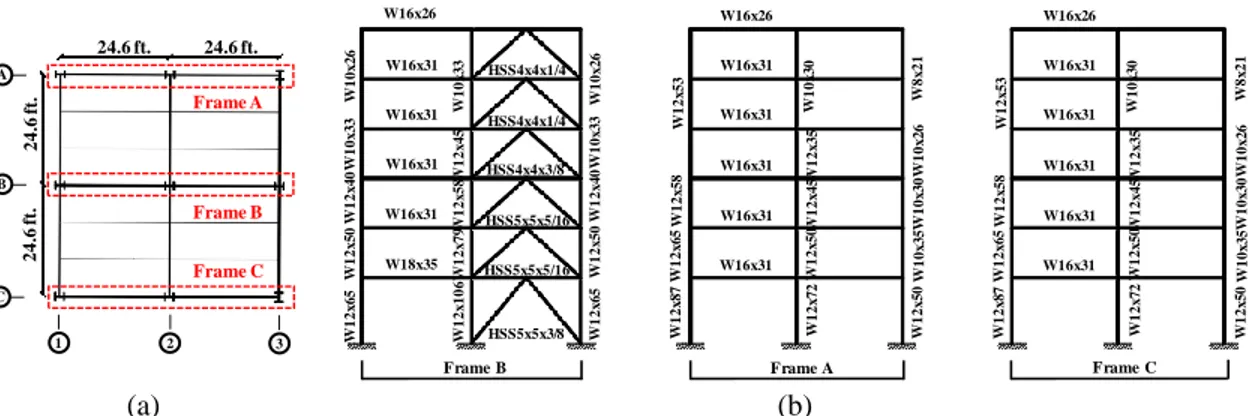
The structure considered in this study is one of the six-story braced frames designed by Goel and his research associates in late 1980s (Goel 1992), namely F4MR. This structure presents an opportunity to evaluate the impact of MFs combined with CBFs for several reasons: (a) the response of this structure together with a group of other structures, have influenced the development of CBFs design requirements based on which early seismic design provisions were recommended; (b) braces in CBF were designed with width-to-thickness ratios (b/t) that are comparable to the current seismic provisions (ANSI/AISC 341-16 2016) to ensure adequate ductility; and (c) it reflects the design philosophy of the early days and represents a good example of the existing structures. The six-story floor plan and the elevation view of the lateral force resisting frames including the steel section sizes are shown in Figure 1.
(a) (b)
Figure 1. Six-story dual structural system: (a) floor plan view; and (b) elevation of braced bay (i.e., Frame B) and unbraced bays (i.e. Frames A and C) with cross-sectional dimensions.
Frame A Frame B Frame C A 1 B C 2 3 24.6 ft. 24.6 ft. 2 4 .6 ft. 2 4 .6 ft. W1 2 x 1 0 6 W1 2 x 7 9W1 2 x 5 8W1 2 x 4 5 W1 0 x 3 3 W1 2 x 6 5 W1 2 x 5 0 W1 2 x 4 0 W1 0 x 3 3 W1 0 x 2 6 W1 2 x 6 5 W1 2 x 5 0 W1 2 x 4 0 W1 0 x 3 3 W1 0 x 2 6 W1 2 x 7 2 W1 2 x 5 0W1 2 x 4 5W1 2 x 3 5 W1 0 x 3 0 W1 2 x 8 7 W1 2 x 6 5 W1 2 x 5 8 W1 2 x 5 3 W18x35 W16x31 W16x31 W16x31 W16x31 W16x26 W16x31 W16x31 W16x31 W16x31 W16x31 W16x26 HSS5x5x5/16 HSS5x5x5/16 HSS5x5x3/8 HSS4x4x1/4 HSS4x4x3/8 HSS4x4x1/4 W1 2 x 5 0 W1 0 x 2 6 W8 x 2 1 W1 0 x 3 0 W1 0 x 3 5 W1 2 x 7 2 W1 2 x 5 0W 1 2 x 4 5W1 2 x 3 5 W1 0 x 3 0 W1 2 x 8 7 W1 2 x 6 5 W1 2 x 5 8 W1 2 x 5 3 W16x31 W16x31 W16x31 W16x31 W16x31 W16x26 W1 2 x 5 0 W1 0 x 2 6 W8 x 2 1 W1 0 x 3 0 W1 0 x 3 5
As illustrated in Figure 1(a), three SFR systems were located on grids A, B, and C. The braced frame with chevron configuration was on one bay of Frame B and the moment frame on the other unbraced bay, whereas in both bays of Frames A and C, SFR systems were moment frames, as seen in Figure 1(b). The first story height was 14.8 feet, while all remaining stories were 11.2 feet. Detailed information on the structure can be found in Hassan (1991). Note that the girder-to-column connections of the chevron-braced bay presented in Figure 1 were moment connections. Thus, this braced bay (in Frame B) is also acting as a moment frame. In a typical design of braced frames, however, these connections are often deemed simple connections. In addition, the base supports of the SFR in all bays were considered perfectly fixed which is also not common in design.
3 CASES OF STUDY AND NONLINEAR PUSHOVER ANALYSIS
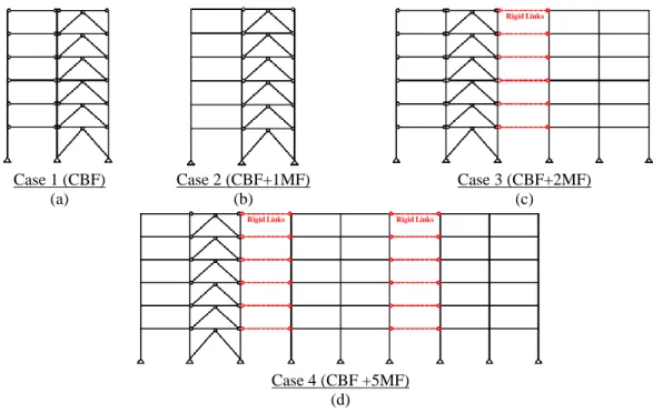
Several cases were derived from the above-described six-story structure to establish the impact of MFs on the CBFs inelastic behavior. Maintaining the original structural configuration and cross-sectional sizes of Frames A, B, and C in Figure 1, four cases were considered, as shown in Figure 2. These cases represent MFs integrated with CBF system with different base shear proportions. The case definitions and their corresponding design base shear fractions are as follows: (a) Case 1, CBF only; (b) Case 2, CBF with one bay of MF, with strength equivalent to 5% of the CBF base shear; (c) Case 3, CBF with two bays of MF, with strength equivalent to 10% of that of CBF; and (d) Case 4, CBF with five bays of MF, with strength equivalent to 25% of the CBF.
Case 1 (CBF) Case 2 (CBF+1MF) Case 3 (CBF+2MF)
(a) (b) (c)
Case 4 (CBF +5MF) (d)
Figure 2. Frame cases considered in this study: (a) Case 1 regards CBF only; (b) Case 2, CBF with one MF; (c) Case 3, CBF with two MFs; and (d) Case 4, CBF with 5 MFs.
These base shear proportions were determined by means of pushover analyses that were exclusively performed on the CBF system, the moment frame next to the braced bay, and one of the two-moment frames located on grids A and C in Figure 1(a), respectively. Note that the six-story frame was modified by incorporating simple connections in the chevron-braced bay, and the
Rigid Links
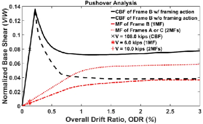
base support of the SFR systems in all bays were assumed to be pinned to be consistent with the current design practice. The results of the pushover analyses are illustrated in Figure 3. From the markers shown at the initial stiffness in Figure 3, one can notice that moment frame in the braced bay has an elastic base shear capacity of 6.0 kips, which is about 5% of that of CBF. This capacity was increased to 10 kips, about 10% of the CBF base shear, when the two-moment frames located on grids A or C were incorporated. Also, a few observations can be made by investigating Figure 3: (a) in the CBF, the contribution of framing action to the strength after braces buckled appears to be significant compared to the scenario when the connections are assumed to be perfectly pinned (without framing action), which is generally the case in the traditional design practice; and (b) the residual post-buckling capacity of CBF w/o framing action is almost equivalent to the post-yielding strength of one moment frame. Note that, the seismic weight was 1356 kips, and the numerical models used for the pushover analyses were built in the Open System for Earthquake Engineering Simulation Platform, OpenSees (McKenna et al. 2000) following an experimental validation discussed in the next section.
Figure 3. Pushover response of CBF and MFs of Frames B and A (or C). 4 NUMERICAL MODELS CALIBRATION
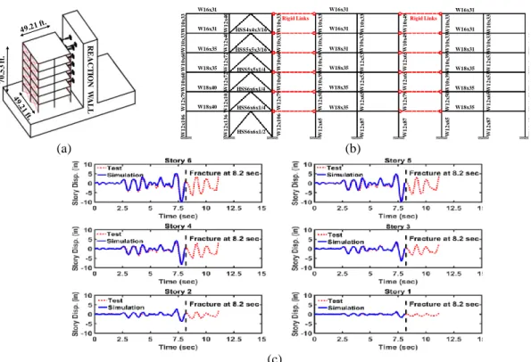
The numerical models of Cases 1, 2, 3, and 4, illustrated in Figure 2, were built as 2D models in OpenSees. The reliability of the models was validated by the pseudo-dynamic test results of a full-scale six-story steel building tested at the Building Research Institute in Japan (Foutch et al. 1986). In fact, the structural scheme of the building designed by Goel (2002) in Figure 1 and the one considered in this study, were originated from the latter test. Under a cooperative research program between the U.S. and Japan in 1982, the building shown in Figures 4(a) and (b) was tested to investigate the seismic behavior of steel structures with different LFRSs, and to provide design recommendations accordingly. The experimental program consisted of four phases. The focus herein is on Phase I program that included a concentrically braced frame with chevron (inverted-V) configuration tested under the 1978 Miyagi-Ken-Oki (N-S) earthquake. As Figure 4(c) compares the simulated displacement histories of each story level with that reported from the experimental test up to fracture of braces that occurred at 8.2 seconds. As can be interpreted from the figure, the tested and simulated displacement histories are in good agreement. Therefore, one can notice that analyzing the developed analytical models (i.e., frames of Cases 1,2,3, and 4) under several ground motions can be considered adequately reliable. Note that a fracture criterion was not introduced in the analytical models, and hence, response beyond 8.2 seconds was not illustrated as discrepancies become significant.
(a) (b)
(c)
Figure 4. Comparison between the results of the analytical simulations of the tested six-story structure of Phase I experimental program with the test response: (a) tested six-story structure; (b) elevation of the
lateral force resisting systems; and (c) simulated story displacement versus that of the test. 5 ANALYSES, RESULTS, AND CONCLUSIONS
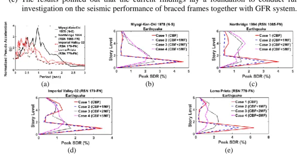
Nonlinear dynamic responses of Cases 1, 2, 3, and 4 subjected to four different ground motion records are studied in terms of story drift ratio (SDR). This was performed to investigate the impact of incorporating MFs designed with three different strength levels on the seismic performance of CBFs. The first fundamental period (T1) of the considered cases are 0.9, 0.82, 0.81, and 0.77 seconds. The unscaled response spectra of the four records are shown in Figure 5(a) and the drift response of the considered cases to these records are plotted in Figures 5(b) through (e). Accordingly, one can observe the following:
(a) The deformation patterns of Case 1 (CBF only) and Case 2 (CBF+1MF) were similar under all applied ground motion excitations. The seismic drift demands were concentrated in the first story level and no apparent trend was observed that MFs designed for 5% of the CBF base shear yield to a uniform drift distribution along the structural height.
(b) As the number of rigid bays and accordingly the participation of MFs to the lateral strength and stiffness increase (i.e., Cases 3 and 4), the mitigation in the inter-story drift demands becomes significant on the order of 50 (Figures 5b, c and d) to 75% (Figure 5e) compared with the other two cases. Although the strength of MFs in Case 3 (CBF+2MF) was based on slight participation of about 10% of the CBF base shear, the peak SDR demand obtained from Case 3 was equal or less than half of that of Case 2 under all ground motions. Thus, incorporating the MFs seemed to have a significant impact on the CBF behavior since a substantial reduction in the demand and a more uniform drift
7 0 .5 3 ft. R EA C T IO N W A LL W1 2 x 1 3 6 W1 2 x 1 0 3W1 2 x 7 2 W1 2 x 7 2 W1 2 x 4 0 W1 2 x 4 0 W 1 2 x 1 0 6 W1 2 x 7 9 W1 0 x 6 0 W1 0 x 6 0 W 1 0 x 3 3 W1 0 x 3 3 W1 2 x 1 0 6 W1 2 x 7 9 W1 0 x 6 0 W1 0 x 6 0W 1 0 x 3 3 W1 0 x 3 3 W1 2 x 8 7 W1 2 x 7 9 W1 2 x 6 5 W1 2 x 6 5 W1 0 x 4 9 W1 0 x 4 9 W 1 2 x 8 7 W1 2 x 6 5 W1 2 x 5 3 W1 2 x 5 3 W1 0 x 3 3 W1 0 x 3 3 W1 2 x 6 5 W1 2 x 5 0 W1 0 x 3 9 W1 0 x 3 9 W1 0 x 3 3 W1 0 x 3 3 W1 2 x 8 7 W1 2 x 7 9 W1 2 x 6 5 W1 2 x 6 5 W1 0 x 4 9 W1 0 x 4 9 W1 2 x 8 7 W1 2 x 6 5 W1 2 x 5 3 W1 2 x 5 3 W1 0 x 3 3 W1 0 x 3 3 W1 2 x 6 5 W1 2 x 5 0 W1 0 x 3 9 W1 0 x 3 9 W1 0 x 3 3 W1 0 x 3 3 W18x40 W18x40 W18x35 W16x35 W16x31 W16x31 W18x35 W18x35 W18x35 W18x31 W16x31 W16x31 W18x35 W18x35 W18x35 W18x31 W16x31 W16x31 HSS6x6x1/4 HSS6x6x1/4 HSS6x6x1/2 HSS5x5x3/16 HSS5x5x1/4 HSS4x4x3/16
demand distribution throughout the height of the CBF were achieved even when such weak and low-redundant moment frames were introduced.
(c) The results pointed out that the current findings lay a foundation to conduct further investigation on the seismic performance of braced frames together with GFR system.
.
(a) (b) (c)
(d) (e)
Figure 5. Applied ground excitations and response of the considered cases: (a) response spectra; (b) peak SDR response to Miyagi-Ken-Oki earthquake; (c) peak SDR response to Northridge earthquake; (d) peak
SDR response to Imperial Valley earthquake; and (e) peak SDR response to Loma Prieta earthquake. References
ANSI/AISC 341-16, Seismic Provisions for Structural Steel Buildings, Chicago (IL): American Institute of Steel Construction, 2016.
Foutch, D. A., Goel, S. C., and Roeder, C. W., Preliminary Report on Seismic Testing of a Full-Scale
Six-Story Steel Building, University of Illinois Engineering Experiment Station, College of Engineering.
University of Illinois at Urbana-Champaign, 1986.
Goel, S. C., Earthquake Resistant Design of Ductile Braced Steel Structures, Stability and Ductility of Steel
Structures under Cyclic Loading, 297-308, 1992.
Hassan, O. F., Modeling of Bracing Members and Seismic Behavior of Concentrically Braced Steel
Structures, PhD Thesis, Horace H. Rackham School of Graduate Studies, University of Michigan,
1991.
Kiggins, S., and Uang, C.-M., Reducing Residual Drift of Buckling-Restrained Braced Frames as a Dual System, Engineering Structures, 28 (11) 1525–1532, 2006.
McKenna, F., Fenves, G. L., and Scott, M. H., Open System for Earthquake Engineering Simulation,
University of California, Berkeley, CA., 2000.
Seker, O., Akbas, B., Seker, P.T., Faytarouni, M., Shen, J. and Mahamid, M., Three-Segment Steel Brace for Seismic Design of Concentrically Braced Frames, Journal of Constructional Steel Research, 137, 211-227, 2017.
Shen, J., Seker, O., Akbas, B., Seker, P., Momenzadeh, S. and Faytarouni, M., Seismic Performance of Concentrically Braced Frames with and without Brace Buckling, Engineering Structures, 141, 461-481, 2017.
Shen, J., Rou, W., Akbas, B., Seker, O. and Uckan, E., 2015. Near-collapse behavior of steel buildings with non-ductile concentrically braced frames. Journal of Constructional Steel Research, 113, pp.101-114.
Uriz, P., Toward Earthquake-Resistant Design of Concentrically Braced Steel-Frame Structures, Pacific Earthquake Engineering Research Center, 2008.
Wen, R., Akbas, B. and Shen, J., 2013. Practical moment–rotation relations of steel shear tab connections.