i
IZMIR KATIP CELEBI UNIVERSITY GRADUATE SCHOOL OF SCIENCE AND ENGINEERING
M.Sc. THESIS
APRIL 2017
NEW GRADE OF THERMOPLASTIC POLYURETHANE WITH HIGH THERMAL CONDUCTIVITY AND LOW COEFFICIENT OF FRICTION
Thesis Advisor: Assoc. Prof. M. Özgür SEYDİBEYOĞLU Seçkin SEMİZ
iii
IZMIR KATIP CELEBI UNIVERSITY GRADUATE SCHOOL OF SCIENCE AND ENGINEERING
APRIL 2017
NEW GRADE OF THERMOPLASTIC POLYURETHANE WITH HIGH THERMAL CONDUCTIVITY AND LOW COEFFICIENT OF FRICTION
Thesis Advisor: Assoc. Prof. Dr. M. Özgür SEYDİBEYOĞLU Department of Material Science and Engineering
M.Sc. THESIS Seçkin SEMİZ Y130111038
NİSAN 2017
İZMİR KATİP ÇELEBİ ÜNİVERSİTESİ FEN BİLİMLERİ ENSTİTÜSÜ
YÜKSEK ISIL İLETİMLİ, DÜŞÜK SÜRTÜNME KATSAYILI YENİ NESİL TERMOPLASTİK POLİÜRETAN
YÜKSEK LİSANS TEZİ Seçkin SEMİZ
Y130111038
Malzeme Bilimi ve Mühendisliği Anabilim Dalı
vii
Seçkin SEMİZ, a M.Sc. student of İzmir Katip Çelebi University student ID Y130111038, successfully defended the thesis entitled “New Grade of Thermoplastic Polyurethane with High Thermal Conductivity and Low Coefficient of Friction”, which he prepared after fulfilling the requirements specified in the associated legislations, before the jury whose signatures are below.
Thesis Advisor: Assoc. Prof. Mehmet Özgür SEYDİBEYOĞLU İzmir Kâtip Çelebi University
Jury Members : Assist. Prof. Hüsnügül Yılmaz ATAY İzmir Kâtip Çelebi University
Assist. Prof. Seçkin ERDEN Ege University
Date of Submission: 28.04.2017 Date of Defense : 28.04.2017
ix
xi ACKNOWLEDGEMENTS
I would like to express my gratitude to my advisor, Assoc. Prof. Mehmet Özgür Seydibeyoğlu for his guidance and suggestions.
I present my thanks to M.Sc. Mechanical Engineer Ozan Devlen from Kastaş Sealing Technologies for their support and guidance during this study. I would like to present my thanks for supplying the materials and material additives, letting me using the test facilities in research and development test center to Kastaş Sealing Technologies. I would like to endless thanks for supporting and believing me during my thesis to my family.
I would like to thank to Res. Assis. Metehan Atagür for helping to perform the material characterization tests and criticism during my study.
xiii Table of Contents
Page
Acknowledgements ... xi
Table of Contents ... xii
List of Tables ... xvii
List of Figures ... xviii
Abbreviations ... xxi
List of Symbols ... xxiii
SUMMARY ... xxv
ÖZET ... xxvii
1. INTRODUCTION ... 1
1.1 Background ... 1
1.2 Definition of hydraulic and pneumatic ... 1
1.2.1 History of fluid power ... 2
1.2.2 Usage of hydraulic and pneumatic systems ... 2
1.2.3 Components of hydraulic and pneumatic systems ... 3
1.2.3.1 Hydraulic and pneumatic cylinders ... 4
1.2.3.2 Pumps, motors and compressors ... 6
1.2.3.3 Control valves and valve symbols ... 7
1.2.3.4 Accumulators ... 8
1.2.3.5 Filters ... 9
1.2.3.6 Reservoirs ... 10
1.2.3.7 Hoses and fittings ... 11
1.2.3.8 Gauges and accessories ... 12
1.2.4 Hydraulic circuit analyses ... 13
1.2.5 Pneumatic circuit analyses ... 13
1.2.6 Differences between hydraulic and pneumatic systems... 14
1.2.7 Sealing element types of hydraulic and pneumatic systems ... 15
1.2.8 General assembly information of sealing elements ... 18
1.2.9 Storage advices for hydraulic and pneumatic sealing elements ... 19
xiv
1.3 Thermoplastic polyurethane material ... 22
1.4 Additives ... 24
1.4.1 Boron nitride (BN) ... 24
1.4.2 Polytetrafluoroethylene (PTFE) ... 26
1.4.3 Molybdenum disulfide (MoS2)... 27
1.4.4 Graphite ... 28
2. MATERIALS AND METHOD ... 29
2.1 Materials ... 29
2.2 Method ... 30
2.2.1 Preparation of the materials for injection molding process ... 30
2.2.2 Injection molding process ... 31
2.2.3 Treatment and sampling materials ... 32
2.3 Characterization ... 33
2.3.1 Hardness testing ... 33
2.3.2 Tensile testing ... 34
2.3.3 Friction force testing ... 34
2.3.4 Fourier transform infrared spectroscopy testing (FTIR) ... 36
2.3.5 Thermal conductivity coefficient testing ... 36
2.3.6 SEM analysis ... 36
2.3.7 Compression set testing ... 37
2.3.8 Hydraulic seal testing on hydraulic seal lifecycle test bench ... 37
3. RESULTS AND DISCUSSIONS ... 39
3.1 Hardness testing ... 39
3.2 Tensile testing ... 40
3.3 Friction force testing ... 42
3.4 Fourier transform infrared spectroscopy testing (FTIR) ... 44
3.5 Thermal conductivity coefficient testing ... 45
3.6 SEM Analysis ... 46
3.7 Compression set testing ... 47
3.8 Hydraulic seal testing via hydraulic seal lifecycle test bench ... 48
4. CONCLUSIONS... 53
xv
APPENDIX ... 56 Curriculum Vitae ... 71
xvii List of Tables
Page
Table 1.1: Some applications of fluid power. ... 3
Table 1.2: Hydraulic and pneumatic directional control valve symbols. ... 7
Table 1.3: Hydraulic and pneumatic differences. ... 14
Table 1.4: Datasheet values of BN. ... 24
Table 1.5: Datasheet values of PTFE. ... 26
Table 1.6: Datasheet values of MoS2. ... 27
Table 1.7: Datasheet values of graphite. ... 28
Table 2.1: Specific properties of neat TPU. ... 29
Table 2.2: Compounding details of samples. ... 30
Table 3.1: Tensile test results. ... 40
xix List of Figures
Page
Figure 1.1: Pascal’s law. ... 2
Figure 1.2: Basic hydraulic system with components... 4
Figure 1.3: Basic pneumatic system with components. ... 4
Figure 1.4: Basic cylinder design with numbered parts. ... 5
Figure 1.5: Forces of a cylinder. ... 6
Figure 1.6: Hydraulic gear pump. ... 7
Figure 1.7: Actuation types of the valves. ... 8
Figure 1.8: Bladder type accumulator. ... 9
Figure 1.9: Filters in hydraulic diagram and ISO symbol. ... 9
Figure 1.10: Pneumatic FRL (Filter, Regulator and Lubricator). ... 10
Figure 1.11: Hydraulic reservoir. ... 11
Figure 1.12: Layers of hydraulic hose. ... 11
Figure 1.13: Fittings pressed hydraulic hose. ... 12
Figure 1.14: Fittings widely used in pneumatic systems. ... 12
Figure 1.15: Hydraulic and pneumatic pressure gauges. ... 12
Figure 1.16: Example of basic hydraulic circuit. ... 13
Figure 1.17: Example of basic pneumatic circuit. ... 14
Figure 1.18: Seals in a typical hydraulic cylinder. ... 15
Figure 1.19: Types of rod seals. ... 16
Figure 1.20: Types of piston seal. ... 16
Figure 1.21: Example hydraulic sealing design for agriculture sector. ... 17
Figure 1.22: Example of hydraulic sealing design for construction sector. ... 17
Figure 1.23: Example of hydraulic sealing design for hydraulic press sector. ... 17
Figure 1.24: Example hydraulic sealing design for mobile hydraulic sector... 18
Figure 1.25: Example of hydraulic sealing design for metal processing sector. ... 18
Figure 1.26: Example of hydraulic sealing design for plastic injection sector. ... 18
Figure 1.27: Challenger space shuttle in 1986. ... 21
Figure 1.28: Operating temperatures of sealing elements materials. ... 21
Figure 1.29: Chemical structure of thermoplastic polyurethane. ... 23
Figure 1.30: Morphology of a thermoplastic polyurethane. ... 24
Figure 1.31: Boron nitride powder. ... 25
Figure 1.32: Polytetrafluoroethylene. ... 26
Figure 1.33: Molybdenum disulfide. ... 27
Figure 1.34: Graphite. ... 28
Figure 2.1: Neat TPU. ... 29
Figure 2.2: Twin screw extruder. ... 31
Figure 2.3: Drying oven for material. ... 31
Figure 2.4: Manufacturing test seals in plastic injection machine. ... 32
Figure 2.5: Plastic injection machine. ... 32
Figure 2.6: Cutting process of sealing elements after injection molding... 33
xx
Figure 2.8: Zwick Roel Z10 tensile testing machine. ... 34
Figure 2.9: Test rig manufactured to compare coefficient of friction. ... 35
Figure 2.10: Test seal assembly. ... 36
Figure 2.11: Compression set test apparatus. ... 37
Figure 2.12: TR012013 Hydraulic rod seal test rig. ... 38
Figure 3.1: Hardness test results. ... 39
Figure 3.2: Elongation of break test results. ... 41
Figure 3.3: Stress at 100% strain results. ... 41
Figure 3.4: Tensile strength test results. ... 42
Figure 3.5: Out-stroke friction forces in average. ... 43
Figure 3.6: Assembly force results. ... 44
Figure 3.7: FTIR spectra of neat and compounded TPU’s. ... 45
Figure 3.8: Thermal conductivity test results. ... 45
Figure 3.9: SEM images at 2000X; a) Neat TPU, b) Sample 4, c) Sample 6, d) Sample 9 e) Sample 11 ... 47
Figure 3.10: Compression set results. ... 48
Figure 3.11: Leakage results in the first test series. ... 49
Figure 3.12: Leakage results in the second test series. ... 50
Figure 3.13: Friction forces in test series 1. ... 50
xxi Abbreviations
TPU Thermoplastic Polyurethane
FTIR Fourier Transform Infrared Spectroscopy SEM Scanning Electron Microscopy
MPa Mega Pascal BN Boron Nitride CS Compression Set
xxiii List of Symbols
σmax Maximum Strength E Young’s Modulus
xxv
NEW GRADE OF THERMOPLASTIC POLYURETHANE WITH HIGH THERMAL CONDUCTIVITY AND LOW COEFFICIENT OF FRICTION
SUMMARY
Today, thermoplastic polyurethane materials are widely used in many different applications. There are many types of thermoplastic polyurethanes which offers different mechanical and chemical properties according to application area. In addition to the existing properties, thermoplastic polyurethane materials mixed with various additives to obtain specific, targeted thermoplastic polyurethane materials in order to impart different properties to the material for application.
In this study, materials of the sealing elements are approached which is one of the most important parts of the hydraulic & pneumatic systems widely used in industry. Nowadays when energy efficiency and product life become vital, it is quite important that prolongation of the sealing element life, increasing the energy efficiency and reducing maintenance requirements for hydraulic & pneumatic sealing elements sector. This study gains importance in terms of bringing the properties such as low coefficient of friction and high thermal conductivity coefficient in materials of hydraulic pneumatic sealing materials without breaking the standard physical and chemical properties of the material.
Standard features expected from hydraulic & pneumatic sealing materials summarized as tensile strength, elongation at break, hardness, deformation under pressure (compression set) and wear resistance. In addition to these properties of standard materials, it envisaged that imparting low coefficient of friction to materials will reduce wearing because of friction and heat formation, imparting high thermal conductivity will facilitate transferring the heat generated from the material to the surrounding area. If these two properties are insufficient, burn spots and abrasions due to temperature increase observed in the working surfaces of the sealing elements. Herewith these problems cause leakage that is the indication of failure. By preventing these situations, the sealing elements will be able to benefit from the sector with higher energy efficiency and longer working life.
Four different additive materials such as boron nitride, MoS2 ,graphite and PTFE were used at three different doses each to gain the specified properties to the thermoplastic material which is used in this study. The base material compounded with the additives was re-granulated with twin-screw extruder and after heat treatment of the materials, test plaques and sealing elements were produced with the help of plastic injection machines.
xxvi
FTIR, thermal conductivity coefficient, tensile, compression set, coefficient of friction and friction tests carried out to examine the properties expected to change. When all the results analyzed according to the tests performed, it has been observing that Sample 6 which has 5% PTFE acquired the targeted properties without deteriorating the existing properties. In this compounded material, the coefficient of thermal conductivity increases and the coefficient of friction decreases while the hardness, stress at 100% strain and compression set values are within acceptable limits.
xxvii
YÜKSEK ISIL İLETİMLİ, DÜŞÜK SÜRTÜNME KATSAYILI YENİ NESİL TERMOPLASTİK POLİÜRETAN
ÖZET
Termoplastik poliüretan malzemeler günümüzde endüstrinin birçok farklı yerinde yaygın olarak kullanılmaktadır. Uygulama alanına göre farklı mekanik ve kimyasal özellikler gösteren termoplastik poliüretanların birçok çeşidi vardır. Mevcut özelliklerin yanında, uygulamaya yönelik olarak malzemeye farklı özellikler kazandırabilmek için termoplastik poliüretan malzemeler çeşitli katkı maddeleriyle karıştırılarak spesifik, hedefe yönelik termoplastik poliüretan malzemeler elde edilmektedir.
Bu çalışmada, endüstride yaygın olarak kullanılan hidrolik ve pnömatik sistemlerin en önemli parçalarından biri olan sızdırmazlık elemanları malzemeleri ele alınmıştır. Enerji verimliliğinin ve ürün ömürlerinin önemli hale geldiği günümüzde hidrolik ve pnömatik sızdırmazlık elemanları ömürlerinin uzatılması, enerji verimliliklerinin arttırılması ve bakım gereksinimlerinin azaltılması hidrolik pnömatik sızdırmazlık elemanları sektörü için büyük önem taşımaktadır. Bu çalışma, hidrolik pnömatik sızdırmazlık elemanları malzemelerinde düşük sürtünme katsayısı ve yüksek ısıl iletim katsayısı gibi özelliklerin malzemenin standart fiziksel ve kimyasal özelliklerini bozmadan malzemeye kazandırılması açısından önem kazanmaktadır. Hidrolik & Pnömatik sızdırmazlık elemanları malzemelerinden beklenen standart özellikler; çekme dayanımı, kopma uzaması, sertlik, baskı altında deformasyon ve aşınma dayanımı olarak özetlenebilir. Standart malzemelerin sahip oldukları bu özelliklerin yanında, malzemelere düşük sürtünme katsayısının kazandırılmasının, malzemenin sürtünmeden kaynaklı aşınmasını ve ısı oluşumunu azaltacağını, yüksek ısıl iletim katsayısının kazandırılmasının da oluşan sıcaklığın malzemeden çevreye transferinin kolaylaştıracağı öngörülmüştür. Bu iki özelliğin yetersiz olduğu durumlarda sızdırmazlık elemanları çalışma yüzeylerinde sıcaklık artışı sebebiyle yanmalar ve aşınmalar gözlemlenmektedir. Sonuç olarak da bu problemler sızdırmazlık elemanı için başarısızlık göstergesi olan sızıntıya sebep olur. Bu durumların önlenmesi sayesinde sızdırmazlık elemanları daha yüksek enerji verimliliği ve daha uzun çalışma ömürleriyle sektörde avantaj elde edebilecektir. Çalışmada kullanılan termoplastik poliüretan malzemeye belirtilen özelliklerin kazandırılabilmesi için boron nitrür, MoS2, PTFE ve grafit gibi dört farklı katkı malzemesi üçer farklı dozajda kullanılmış ve termoplastik poliüretan malzeme ile çekilerek toplamda on iki farklı çeşit oluşturulmuştur. Katışkıları yapılan malzemeler çift vidalı ekstruder ile çekilmiş ve ısıl işlemleri yapıldıktan sonra plastik enjeksiyon makinası ile sızdırmazlık elemanı ve test plakaları üretilmiştir.
xxviii
Değişmesi beklenen özelliklerin incelenebilmesi için FTIR, ısıl iletim katsayısı, çekme kopma, sıkıştırma, sürtünme katsayısı ve özel test tertibatıyla sürtünme karşılaştırma testleri yapılmıştır.
Yürütülen testlere göre tüm sonuçlar incelendiğinde %5 PTFE ile oluşturulmuş altı numaralı malzemenin mevcut özellikler bozulmadan hedef özellikleri malzemeye kazandırdığı gözlemlenmiştir. Bu malzemede sertlik, %100 uzama altındaki gerilme ve baskı altında deformasyon değerleri kabul edilebilir sınırlar içinde kalırken, ısıl iletim katsayısı değeri artmış ve sürtünme katsayısı değeri azalmıştır.
1 1. INTRODUCTION
1.1 Background
Usage of thermoplastic polyurethane materials in hydraulic and pneumatic sealing systems is increasing day by day. The biggest manufacturers of thermoplastic materials in the world are working on developing new properties to existing materials according to customer requirements.
Accompany with industrial developments, efficiency of energy is an increasing trend all around the world. Energy efficiency is a blooming trend regarding industrial developments of companies around the world. On the other hand, increasing efficiency of sealing system studied in hydraulic and pneumatic sector like in every segment of industry. The first step of this increase of efficiency is using the right material for each application. On the other hand, the selected material must provide several necessities like minimum leakage, performing silently, maximum life cycle and shelf life, avoiding get warm due to friction and minimum friction coefficient. In this study, it is aimed to improve sealing properties and extend life cycle of thermoplastic polyurethane.
1.2 Definition of hydraulic and pneumatic
There are three methods in industry for power transfer from one to another point. Firstly, mechanic power transfer is possible with usage of shafts, chains, belts and gears. Secondly, electrical power transfer is only possible with the existence of wires, transformers and other various elements. In addition, the third method is fluid power transfer which solely through fluid or gas in an imprisoned space.
Fluid power technology transfers and controls the forces through mechanical systems and elements where environmental conditions restricted with the help of pressurized fluids. Gases and fluids considered as well fluids. Fluid power systems combine both hydraulic (stands for water in Greek) and pneumatic (stands for air in Greek)
2
systems. Hydraulic systems used widely in industry for huge forces needed for the comparison with pneumatic systems. If you compare the first setup costs, hydraulic systems are more expensive than pneumatic systems. The first reason of this expensiveness is pressure. In hydraulic systems, the media has to be incompressible fluid as water and oil. For this reason, the pressure of the system theoretically can increase unlimitedly. The media that used in pneumatic systems is air that we breathe. Air compressors pressurize the air up to 10 - 12 bar. Pressurizing the air more than 10 bar is energy loss because of compressibility of air. That is why pneumatic systems are limited with 10 - 12 bar.
1.2.1 History of fluid power
Fluid power technology was invented in 1650 with the discovery of Pascal’s law. According to Pascal (1650), “in a fluid at rest in a closed container, a pressure change in one part is transmitted without loss to every portion of the fluid and to the walls of the container”. With this law, Pascal laid the foundations for the next development of hydraulics with the hydrostatic law. Joseph Bramah considered as a founder of hydraulics technology. In the lights of this information, hydraulic systems started to be a part of industry.
Figure 1.1: Pascal’s law. 1.2.2 Usage of hydraulic and pneumatic systems
Hydraulics and pneumatics are widely used in industry to produce of services and goods that almost covered by all sectors. A portion of the business fields are reliant on the capacities that liquid power manages. Some of the fluid power applications illustrated on Table 1.1.
3
Table 1.1: Some applications of fluid power [3]. Farming Ploughs, water and chemical sprayers, harvesters etc.
Automobiles Steering systems, brake systems, suspension systems, hydrostatic transmission systems etc. Construction
industry/equipment Excavators, lifts, bucket loaders, crawlers, post-hole diggers, road graders, road cleaners, road maintenance vehicles, tippers etc. Defense Missile-launching systems, navigation controls etc.
Fabrication
industry Hand tools such as pneumatic drills, grinders, borers, riveting machines etc. Food and beverage All types of food processing equipment, wrapping, bottling etc.
Foundry Full and semi-automatic molding machines, tilting of furnaces, die-casting machines etc. Glass industry Vacuum suction cups for handling etc.
Instrumentation Used to create/operate complex instruments in space rockets, gas turbines, nuclear power plants, industrial labs etc. Jigs and fixtures Work holding devices, clamps, stoppers, indexers etc.
Machine tools Automated machine tools, numerically controlled (NC) machine tools etc. Materials handling Jacks, hoists, cranes, forklifts, conveyor systems etc.
Medical Medical equipment such as breathing assistors, heart assist devices, cardiac compression machines etc.
Movies Special-effect equipment etc.
Mining Rock drills, excavating equipment, ore conveyors, loaders etc. Newspapers and
periodicals Edge trimming, stapling, pressing, bundle wrapping etc.
Oil industry Off-shore oil rigs etc.
Plastic industry Automatic injection molding machines, raw material feeding, jaw closing, movement of slides of blow molder etc.
1.2.3 Components of hydraulic and pneumatic systems
Fluid power systems are power transferring units employing pressurized fluids for transmitting energy from an energy generating source to an energy using point to accomplish useful work. Figure 1.2 and Figure 1.3 shows sample hydraulic and pneumatic systems with their basic components.
4
Figure 1.2: Basic hydraulic system with components [2].
Figure 1.3: Basic pneumatic system with components [3].
1.2.3.1 Hydraulic and pneumatic cylinders
Fluid powered cylinders convert fluid pressure created by compressors or pumps to a linear or rotary mechanical movement. When fluid pressure acts on the piston, the pressure transmitted to the piston rod, resulting in linear motion. The piston rod thrust force created by the fluid pressure acting on the piston is easily determined by multiplying the line pressure by the piston area. In general, cylinders are linear actuators that can force and draw a heap however, when it mounted on a revolving joint straight move makes as a turning movement. The principle of operation is basically explainable with Pascal’s law. There are couple different types of cylinders depending on application of system. Single acting cylinders have a one-way movement creation. Instroke motion of the load occurs with gravity or a loaded spring. The second type of cylinders are double acting ones. This type of cylinders which are most common, has two connection ports for media in and out. One of the port is for outstroke motion and the second one is for instroke motion. This type of
5
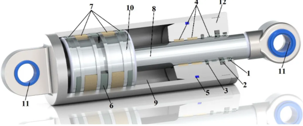
cylinders transforms the fluid power to linear motion for forward and backward direction. Figure 1.4 shows components of typical double acting hydraulic cylinder.
Figure 1.4: Basic cylinder design with numbered parts. The cylinder located above, has the parts detailed below;
1: Wiper seal 2: Rod seal 3: Rod buffer seal 4: Rod guiding rings 5: Static seal
6: Piston seal
7: Piston guiding rings 8: Rod
9: Bore / Barel 10: Piston
11: Cylinder joints 12: Head
Basically, hydraulic and pneumatic cylinders occur from the same parts. When the operating pressures considered, some differences needed in designs. First of it is bore material and thickness. In pneumatic applications bore material is usually aluminum and thickness is couple millimeters on the grounds that operation pressure limited to 10 bar. In the hydraulic applications, bore and the rod materials are usually hardened steel.
6
Calculation of pressure–force transformation is force equals pressure cross area. There is a point that must be considered. The area used for pushing force is smaller than the other side. This means pushing and pulling forces are different as shown below.
Figure 1.5: Forces of a cylinder.
The area shown as Acap is bigger than the area shown as Arod. That is the reason why the force F1 is bigger than force F2 under the same pressure value.
1.2.3.2 Pumps, motors and compressors
In hydraulic systems, duty of pressurizing the media is performed by a hydraulic pump driven by electric motor or combustion engine. Driving a pump is usually performed by an electric motor. Combustion engines are used in mobile hydraulic systems or precaution situations like moments when electricity can be cut off. The most common hydraulic pumps are gear, vane and radial piston pumps. If the media is air which means pneumatic system, duty of pressurizing the media is performed by air compressors. Ideal hydraulic pump and motor are defined by the relations between fluid pressure P, flow Q, shaft torque T and velocity w. In pneumatic applications choosing the compressor is determined according to pressured air flow needed. Consequently, pumps are source of pressurized liquid media for hydraulic systems, compressors are source of pressurized air for pneumatic systems.
If the motion needed is rotary, motors can be used as actuator in hydraulic and pneumatic systems. Motors are powered by pressurized media and transforms fluid power to mechanical power. A basic hydraulic gear pump is shown in Figure 1.6.
7
Figure 1.6: Hydraulic gear pump.
1.2.3.3 Control valves and valve symbols
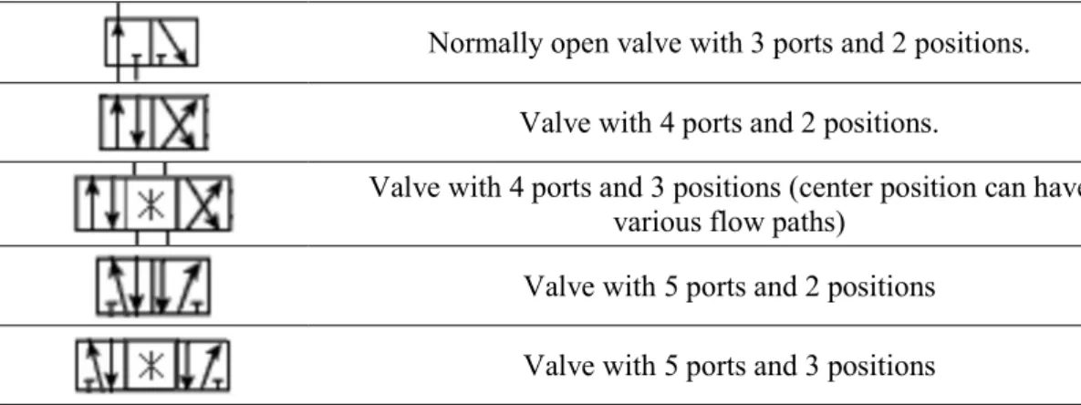
Valves are important parts of the fluid power systems and they appear in all fluid power system. Valves are categorized by purpose, which includes directional control valves for transferring fluid flow to one of the cylinder or hydro motor port, pressure control valves for regulating the fluid pressure at a constant value and flow control valves for curbing the flow value in a line which determines the velocity of the cylinder. Valves are named by the number of ports and operating positions. For example, a 5 way and 3 position valves are commonly found in pneumatic systems one port for supplying the pressured air, one port for exhaust of the system and three ports for positioning the cylinder. In the first position, which is middle valve doesn’t let the air flew. Valve must be triggered to change the spool position. This trigger can be an electrical spark. When the spool changed position, air starts to fill a port of the cylinder. At the same time other port of the cylinder is connected to exhaust line to make the pressure equal with atmosphere. For changing the motion direction, other coil of the valve is triggered and connections are reversed. Table 1.2 shows hydraulic and pneumatic valve symbols.
Table 1.2: Hydraulic and pneumatic directional control valve symbols.
Valve Detail Symbol
Normally closed valve with 2 ports and 2 positions.
Normally open valve with 2 ports and 2 positions.
8
Normally open valve with 3 ports and 2 positions.
Valve with 4 ports and 2 positions.
Valve with 4 ports and 3 positions (center position can have various flow paths)
Valve with 5 ports and 2 positions
Valve with 5 ports and 3 positions
Actuation types of the valves are shown in Figure 1.7. In the figure, type a symbols push button, type b symbols lever, type c symbols spring return, type d symbols solenoid and type e symbols pilot line actuating valve.
Figure 1.7: Actuation types of the valves.
1.2.3.4 Accumulators
Accumulators are commonly used and important parts of hydraulics systems for temporary storing pressurized oil in system. Accumulators supplies temporary peak fluid power, when flow rate is insufficient. If the system aims a pure and smooth motion, accumulators take a position as shock absorber. These important components of the hydraulic systems connected to pressure line directly. In case of pressure decreasing, accumulators feeds the system and keeps the pressure constant. Accumulators are equivalent to capacitors in an electrical system and to a spring in mechanical system. The most common accumulators are bladder type accumulators. They pre-charged with nitrogen gas according to operating pressure. Selection of accumulator type and volume made according to fluid’s pressure and flow rate needed. Cross section of a bladder type accumulator is shown in Figure 1.8.
9
Figure 1.8: Bladder type accumulator [4].
1.2.3.5 Filters
During the operation of the hydraulic system, media picks up contaminating particles from outside of the cylinder. There are kinds of hydraulic cylinders that work in dirty environments or places too much dusty. In consequence of wearing of the wiper, foreign matters like dust or dirt contaminates the media. These dirt particles are tiny grit that cause additional abrasive wearing. Clumps of particles can clog tiny clearances in precision valves and cylinders that can lead to also corrosion [1]. In every type of hydraulic systems, components need filters in the hydraulic circuit. Figure 1.9 shows hydraulic filters in circuit. The filter numbered 1 is pressure filter. It allows eliminating particles from pressured oil. The filter numbered 2 is return line filter. It allows eliminating particles form non-pressured oil at the end of the hydraulic circle.
10
The aim of pressure filter is protecting the valves and cylinders from particles. However, if the hydraulic oil contaminated in valves of cylinders, return line filter eliminates the dirt from oil. Therefore, the media of hydraulic system is always keeps the purity. Choosing of the right filter element done according to fluid flow, maximum pressure of the system and the dirt’s particle size that will be allowed. In the pneumatic systems, there is one filter needed. At the beginning of the air connection of every pneumatic system, air filter, regulator and lubricator should be included. An air filter cleans compressed air. It traps solid particles (dust, dirt and rust) and separates liquids (water and oil) entrained in the compressed air. Duty of regulators is setting the operating pressure of the system. The combination of filter, regulator and lubricator is called as FRL. A basic FRL is shown in Figure 1.10 below.
Figure 1.10: Pneumatic FRL (Filter, Regulator and Lubricator) [5].
1.2.3.6 Reservoirs
The main aim of reservoirs in hydraulic systems is providing hydraulic fluid at room temperature in atmospheric pressure. Basically, a reservoir is oil storage tank connected to the atmosphere through a breather. Reservoirs have hydraulic components like pumps and motors valves and lines on it. The fluid returned to tank is always hotter than the fluid in reservoir. To avoid warming the fluid in reservoir, heat exchangers used to cool the fluid. Heat exchangers work according to reservoir temperature. If the temperature of reservoir exceeds the limit temperature for system (usually limit is 50 ºC for hydraulic systems) heat exchange cools the fluid. Therefore, reservoir temperature is always limited to preset temperature value. A hydraulic reservoir needs cleaning periodically. For reaching to inner surface of the
11
reservoir there must be a detachable cap which is called man hole. Figure 1.11 shows an ordinary hydraulic reservoir.
Figure 1.11: Hydraulic reservoir [6].
1.2.3.7 Hoses and fittings
Transmitting the pressurized media among various components is done with hoses and fittings. Hoses used in hydraulic systems have couple layers according to system pressure. In the innermost layer is a hose that transmits the fluid. The outer layer of it is reinforcement fibers. The outmost layer of the hose is cover. Number and material of layers can be change according to system pressure. Hose type is chosen according to fluid pressure and flow rate. Figure 1.12 shows the layers of a basic hose.
Figure 1.12: Layers of hydraulic hose.
For connecting the hydraulic hoses to a port, fittings must be used. Diameter of the fittings are choosen according to flow rate. Fittings are pressed to hoses by hydraulic press according to customer’s special requirements. A standard hydraulic hose is shown in Figure 1.12.
12
Figure 1.13: Fittings pressed hydraulic hose.
In pneumatic systems, pressure is limited to 10 – 12 bar because of the compressibility of the air. Due to standard air pressure, pneumatic hoses are standard. The only variable thing is hose diameter. Usually pneumatic hoses made from thermoplastic polyurethane. To connecting the pneumatic hoses there are different types of fittings as shown in Figure 1.14.
Figure 1.14: Fittings widely used in pneumatic systems.
1.2.3.8 Gauges and accessories
Gauges are widely used in hydraulic and pneumatic systems to observe operating pressure. Gauges are important parts of hydraulic and pneumatic systems to control the pressure in case of over loading. Figure 1.15 shows hydraulic and pneumatic gauges.
13
Observing the system pressure in different points on hydraulic systems, makes the system safer.
1.2.4 Hydraulic circuit analyses
Figure 1.16 shows a basic hydraulic circuit. This hydraulic system incorporates a hydraulic pump, a 4 way, 3 position, center off valve and double acting hydraulic cylinder. The pressure relief valve that limits the maximum pressure of the hydraulic system takes place between the pump and return line. Operator can control the system pressure on pressure gauge. If a failure occurs, operators can interfere to the system. Directional control valve has 4 ports and 3 final positions. As shown in valve figure, at the two opposite sides of the valve, it has two solenoid control devices that allow changing the valve positions. At the middle position of valve, all the ports are off which means hydraulic cylinder locked under pressure. Unless the solenoid triggered with an electrical spark, cylinder cannot change the position. In these types of applications, cylinder can act and wait at the specific position. If one solenoid is triggered, cylinder moves to a direction. If another solenoid is triggered, cylinder moves to another direction. Hydraulic elevators use this design to wait at the target floor. Valve has four ports, which are; pressure line, tank line, cylinder forward pressure line and cylinder backward pressure line. Tank line is used for transferring the oil at the end of the circuit.
Figure 1.16: Example of basic hydraulic circuit.
1.2.5 Pneumatic circuit analyses
Figure 1.17 shows a basic pneumatic circuit. This pneumatic system includes a FRL (Filter, Regulator and Lubricator), 5 way, 2 position directional control valve and pneumatic cylinder. Compressor supplies the air for system. At the beginning of the
14
pneumatic circuits, first pneumatic component is always FRL. This component firstly filters the air from dust, oil and particles. After filtering the air regulator sets the operating pressure. Operating pressure is set according to needed force. Regulated air is lubricated in lubricator. After this point, pressurized air is appropriate for using in pneumatic system. Directional control valve is normally supplies air to cylinder’s backward port (Port B). In this position of valve, port A is connected to atmosphere to relief the pressure. Valve is controlled by mechanical button to change the position. If you push the button on valve, valve changes the positon and cylinder moves forward (outstroke). When the mechanical button is relieved, cylinder moves backward (instroke). In these types of valves which have no middle position, cylinder cannot wait at the position between minimum and maximum stroke points.
Figure 1.17: Example of basic pneumatic circuit.
1.2.6 Differences between hydraulic and pneumatic systems
Fluid power devided into two areas. Hydraulics and pneumatics differ in several ways, but the most notable fact is each system uses a different media. Both systems have their own distinct advantages and ideal applications such as heavy lifting and operating costs. The main differences are detailed in Table 1.3 below;
Table 1.3: Hydraulic and pneumatic differences.
Hydraulic Systems Pneumatic Systems
Uses a relatively incompressible liquid Uses compressible air
Slow, smooth motion Quick, jumpy motion
Very precise Not as precise as hydraulics
15
Not as clean (some leakage exist) Generally cleaner Pressures of 30 to theoretically unlimited Pressures of around 8 bar
Complicated installation Easy installation
Limited energy storage High energy storage
Medium noise High noise
High peak power Medium peak power
High operating cost Medium operating cost
High maintenance cost Low maintenance cost
As detailed above, pneumatic systems are cheap for setup costs but if the system needs high forces and smooth motions, hydraulic systems are always preffered. Both systems are suitable for automation control easily under favour of PLC and software.
1.2.7 Sealing element types of hydraulic and pneumatic systems
Hydraulic and pneumatic seals are mechanical devices placed under compression between two metal objects, to prevent the escape of fluids or gases. Seals are named according to part of the cylinder that will be sealed.
Figure 1.18: Seals in a typical hydraulic cylinder.
Piston seal acts as pressure barrier and prevents fluid passing the piston. This seal type is important for controlling the cylinder motion and position. Rod seal acts as pressure barrier and keeps operating fluid inside the cylinder. Rod seal is important for preventing the leakage to the out of the cylinder and also it regulates the fluid film which extends the life cycle of the surfaces. This fluid film inhibits the rod from corrosion and lubricates all parts of the rod design that includes guide elements, rod seal, buffer seal and wiper seal. Buffer seal protects the rod seal from sudden fluid pressure peaks. It also keeps the system contaminants such as dirt or metal particles
16
from damaging the rod seal. Wiper seal inhibits entering the contaminants to cylinder and hydraulic system. On the other hand, wiper seal accepts the lubrication film back into the cylinder when the rod retracts. Guide rings locate both of piston and rod designs. They keep the piston and bore or rod and head accurately centered in the cylinder assembly. Guide rings are the most important parts of the cylinders with the duty of centering the cylinder parts. Life time of the seals will be too short because of the wearing in an uncentered cylinder design. There are different rod seal and piston seal geometries as shown in figure 1.19 and figure 1.20.
Figure 1.19: Types of rod seals [7].
Figure 1.20: Types of piston seal [7].
There are different types of sealing element geometries and materials according to application area, operating temperature, speed and pressure. First step of designing a hydraulic or pneumatic cylinder is specifying the conditions that the cylinder will be operated under. After specifying maximum velocity, operating pressure and maximum environment temperature, seal design can be chosen. Seal designs are detailed according to sectors below;
Agriculture Hydraulic Seal Design Example;
This design includes Kastaş K06 wiper seal, K22 rod seal, K86 guiding element and K85 static seal in rod design, K18 piston seal and K83 static seal in piston design.
17
Rod Design Piston Design
Figure 1.21: Example hydraulic sealing design for agriculture sector [7]. Construction Machinery Seal Design Example;
This design includes Kastaş K05 wiper seal, K33 and K35 rod seal, K75 guiding element and K84 static seal in rod design, K19 piston seal, K75 and KBT guiding elements and K81 static seal in piston design.
Rod Design Piston Design
Figure 1.22: Example of hydraulic sealing design for construction sector [7]. Hydraulic Press Seal Design Example;
This design includes Kastaş K11 wiper seal, K22 and K35 rod seal and K73 guiding element in rod design, K17 piston seal, K73 and KBT guiding elements in piston design.
Rod Design Piston Design
Figure 1.23: Example of hydraulic sealing design for hydraulic press sector [7]. Mobile Hydraulic Seal Design Example;
This design includes Kastaş K12 wiper seal, K22 and K29 rod seal, K73 guiding element and K84 static seal in rod design, K49 piston seal, KBT guiding elements and K83 static seal in piston design.
18
Rod Design Piston Design
Figure 1.24: Example hydraulic sealing design for mobile hydraulic sector [7]. Metal Processing Seal Design Example;
This design includes Kastaş K06 wiper seal and K01 rod seal in rod design, K03 piston seal in piston design.
Rod Design Piston Design
Figure 1.25: Example of hydraulic sealing design for metal processing sector [7]. Plastic Injection Machines Seal Design Example;
This design includes Kastaş K705 wiper seal, K22 and K35 rod seal and K73 guiding element in rod design, K17 piston seal, KBT and K73 guiding elements in piston design.
Rod Design Piston Design
Figure 1.26: Example of hydraulic sealing design for plastic injection sector [7].
1.2.8 General assembly information of sealing elements
There are many problems due to incorrect assembly of hydraulic and pneumatic sealing elements. It is vital that assembly rules should be obeyed in order to make successful applications in hydraulic and pneumatic cylinders.
19
It is very important that before assembly of the components, the entire system and the fitting components must be cleaned out.
The measures of housing and the seal, radius, the chamfer and the surface quality must be checked and cleaned out.
The burs on sharp edges are very dangerous.
The cleanliness of the sealing elements should be checked. Dimensions of the groves must be checked according to sealing element supplier advices.
All the sealing elements should be installed after being oiled with system oil. Installation tools with sharp edges should not be used.
Uncontrolled heating of sealing elements before fitting is ruther dangerous. In case of carrying out final procedures (ie. Painting), the heat over 80ºC should
be avoided.
1.2.9 Storage advices for hydraulic and pneumatic sealing elements
Storage of sealing components may bring about to chemical and physical changes. This could be caused by combined factors.
Oxygen Ozone
Direct sun light High temperature Ultra violet rays Humidity
Stored in good conditions, polyurethane materials can keep their chemical and physical features in long periods.
Environment, moisture and temperature;
Ideal temperature for storage of sealing elements is between 5°C and 25°C and moisture rate should be about 60%. In addition to those direct heat contacts are not recommended.
20 Dirt;
It may change the mechanical features of products. Therefore, before storage environment must be cleaned out.
Oxygen and ozone;
They are oxidizing agents like oxygen. Ozone is especially a destroying agent. Deformation;
Deformation should be avoided during storage. Rubber parts and thermoplastic seals should be kept away from coercive forces and squeezing because they cause a rapid change in mechanical features and endurance against agents in nature.
Contact with grease and hydraulic liquids;
Any contact with solvents, oils and other liquids should be avoided.
1.2.10 Importance of choosing the right material for sealing elements
For a sealing element, maybe the most important factor is material. Even if sealing element type is a right choice, sealing performance is determined according to sealing element material. Some of the materials are suitable for high velocities, some of them are suitable for high pressures and some of them are suitable for high temperatures. The first step of choosing the right material is determining the conditions of hydraulic or pneumatic cylinder. If the designer ignores the conditions of operating environment during the choosing the seal, sealing element will fail in short term. The biggest example of this situation is Challenger space shuttle.
In January 28, 1986, Challenger space shuttle disaster was attributed to the malfunctioning of an o - ring. After 73 seconds of Challenger’s launch, a viton o - ring which had been designed to separate the sections of the rocket boosters, had failed due to cold temperatures on the morning of the launch. After blowing up of Challenger with seven crew, investigation revealed that the o-ring seal on Challenger’s solid rocket booster, which had become brittle in the cold temperatures, failed. Flames then broke out of the booster and damaged the external 2 million liter of fuel fulled tank, in causing the spacecraft to disintegrate [8].
21
Figure 1.27: Challenger space shuttle in 1986 [8].
Maybe, the sealing elements are the cheapest parts of the hydraulic and pneumatic systems, but as in the example, system does not matter without a proper sealing element and material.
For choosing the material of sealing element for an application, acronym “TEMP” can be used.
“T” is for temperature;
All of the elastomer, thermoset and thermoplastic materials offer an operating temperature range. That is why choosing of the material must be optimized selection. Some of the seal materials and operation temperature ranges are given in Figure 1.28.
Figure 1.28: Operating temperatures of sealing elements materials [9]. “E” is for environment;
Life time cycle of the sealing element is predicted according to environment temperature, humidity and chemical effects. All of the environment conditions must be appropriate for sealing element material.
22 Seal “M” is for media;
There are hundreds of different sealing element materials. Hydraulic and pneumatic sealing element sector needs all of these materials because there are many different medias used in hydraulic or pneumatic cylinders. Sealing element material shall not be degraded after exposing the fluid media. Chemical compatibility guide is given in Appendix A.1.
“P” is for pressure;
System pressure is an important criterion to determine the cylinder design like thickness of bore, cylinder steel material and sealing element geometry and material. System pressure and media type of hydraulic cylinder specifies the sealing element design.
1.3 Thermoplastic polyurethane material
Thermoplastic polyurethane (TPU) is a inimitable grade of plastic created when a polyaddition reaction occurs between a diisocyanate and one or more diols.
Initially created in 1937, this adaptable polymer is delicate and processable when warmed, hard when cooled and equipped for being reprocessed various circumstances without losing basic uprightness. Used either as a malleable engineering plastic or as a replacement for hard rubber, TPU is renowned for many things including its: high elongation and tensile strength; its elasticity; and to varying degrees, its ability to resist oil, grease, solvents, chemicals and abrasion [10].
A wide range attributes offered by TPU are make this material well known over a range markets and applications. TPU is characteristically adaptable and it can be expelled or infusion shaped on conventional thermoplastic assembling hardware to make strong segments.
Principally there are three substance classes of thermoplastic polyurethane;
Polyether TPUs are the greatest compound class of TPU. This sort of TPU has marginally lower gravity than other two chemical classes. Polyether TPU offers low temperature adaptability, hydrolysis resistance and great abrasion and tear strength that are really important parameters for a sealing element material.
23
Polyester TPUs is the second biggest class of TPU. The most vital property of this class is being compatible with PVC and other polar plastics. Properties are unaffected by oils and chemicals, provide excellent abrasion resistance and offer good physical properties.
Polycaprolactone TPUs have the inherit toughness and resistance of polyester based TPUs combined with low temperature performance and a relatively high resistance to hydrolysis. They are ideal raw material for hydraulic and pneumatic seals [10].
Thermoplastic polyurethane materials can also be subdivided into aromatic and aliphatic varieties;
Aromatic TPUs in lights of isocyanates are workhorse items and can be utilized in applications that require flexibility, strength and toughness.
Aliphatic TPUs in lights of isocyanates are light steady and offer excellent optical clarity. They are usually utilized in interior and exterior applications of automotive sector and as laminating films to bond glass and polycarbonate together in the coating industry.
Thermoplastic polyurethane is a multiphase piece copolymer that is created when three basic raw materials are combined together in a specific way. The components required to produce a thermoplastic polyurethane are;
A polyol or long chain diol
A chain extender or short chain diol A di isocyanate
24
The smooth block, consisting of a polyol and an isocyanate, is in charge of for the resilience and elongation of a TPU. The strong block, built from a chain extender and isocyanate, gives a TPU its toughness and physical performance properties.
Thermoplastic materials have no chemical cross links unlike thermoset rubbers. Figure 1.30 demonstrates how physical cross links melt out under heat and repack when the material is cooled. This physical cross link gives reprocessable property to the thermoplastic material.
Figure 1.30: Morphology of a thermoplastic polyurethane.
The physical properties of thermoplastic polyurethane depend on the structure of the backbone. They can be tailored to have flexibility, hardness, high strength.
1.4 Additives
For ensuring the intended properties on thermoplastic polyurethane, compounded additives are listed below.
1.4.1 Boron nitride (BN)
Henze HeBoFill 511 powder was used as boron nitride additive. HeBoFill 511 boron nitride powder is the appropriate filler for plastic materials. Typical values of HeBoFill 511 are detailed below.
Table 1.4: Datasheet values of BN [12].
Properties Value Unit
Color white -
Purity 98.5 %
Oxygen 1.3 %
25
Spec. Surf. Area 14 m2/g
Median Grain Size 10 µm
Boron nitride is a chemical compound with the BN chemical formula that discovered in the early 19th century was not developed as a commercial material until the latter half of the 20th century [13]. This compound consists of equal numbers of boron and nitrogen atoms. Hexagonal form of BN corresponds to graphite is the most stable and softest among BN polymorphs, and is therefore used as a lubricant. Boron nitride has thermal and chemical stability. Boron nitride can be synthesized in hexagonal and cubic forms.
Hexagonal Boron Nitride (h-BN) Excellent lubricating properties
Machinable using conventional metal cutting techniques High dielectric breakdown strength
High volume resistivity Good chemical inertness Cubic Boron Nitride (c-BN)
Second hardest material known, inferior only to diamond High thermal conductivity
Excellent wear resistance Good chemical inertness
26
In this study, HeBoFill® 511 Boron nitride powder is used for obtaining the intended properties. Due to the high purity, low density and the intrinsic high thermal conductivity, boron nitride is the appropriate filler for plastic materials in order to increase their heat transfer capability.
1.4.2 Polytetrafluoroethylene (PTFE)
In this study, 3M Dyneon TF9205 is used as PTFE filler. This additive was kindly provided by Kastaş Sealing Technologies.
Polytetrafluoroethylene (PTFE) is a synthetic fluoropolymer of tetrafluoroethylene that discovered in 1938. Polytetrafluoroethylene, or PTFE, is made of a carbon backbone chain, and each carbon has two fluorine atoms attached to it.
Figure 1.32: Polytetrafluoroethylene.
PTFE is a vinyl polymer and its structure is similar to polyethylene. Polytetrafluoroethylene is made from the monomer tetrafluoroethylene by free radical vinyl polymerization. One of the most well-known PTFE brands is Teflon produced by DuPont Corporation.
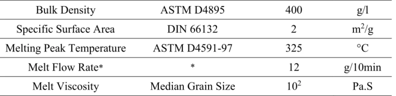
PTFE is a well known material with the properties of extremely low coefficient of friction, high thermal stability, high electrical resistance and strength of corrosive environments. 3M Dyneon TF9502 properties are detailed below.
Table 1.5: Datasheet values of PTFE [14].
Properties Test Method Value Unit
27
Bulk Density ASTM D4895 400 g/l
Specific Surface Area DIN 66132 2 m2/g
Melting Peak Temperature ASTM D4591-97 325 °C
Melt Flow Rate* * 12 g/10min
Melt Viscosity Median Grain Size 102 Pa.S
*The measurements are carried out at 372°C (701°F) (test weight 2.16 kg, die diameter 1.0 mm). 1.4.3 Molybdenum disulfide (MoS2)
Molybdenum disulfide is the inorganic compound with the formula MoS2. It is composed of only two elements; molybdenum and sulfur. MoS2 is relatively unreactive. It is unaffected by dilute acids and oxygen. In appearance, molybdenum disulfide is similar to graphite. It is widely used as a solid lubricant because of its low friction properties and robustness.
Figure 1.33: Molybdenum disulfide.
In this study, ORAPI OR05 is used as MoS2. This additive was kindly provided by Kastaş Sealing Technologies. Specific properties of this material are presented below.
Table 1.6: Datasheet values of MoS2 [15].
Properties Value Unit
Color black -
Crystalline structure Hexagonal -
Average granulometry 2 micron
Specific surface 0.35 m2/g
28 1.4.4 Graphite
Graphite is a crystalline form of carbon, a semimetal, a native element mineral, and one of the allotropes of carbon. Graphite is the most stable form of carbon under standard conditions. Therefore, it is used in thermochemistry as the standard state for defining the heat of formation of carbon compounds. Graphite is an excellent conductor of heat and electricity and it has extremely high natural strength and stiffness compared to other materials. At the same time, it is one of the lightest of all reinforcing agents and has high natural lubricity.
Figure 1.34: Graphite.
Orion Printex 60A is used as graphite. This additive was kindly provided by Kastaş Sealing Technologies. Specific properties of this material are presented below.
Table 1.7: Datasheet values of graphite [16].
Properties Test Method Value Unit
Color - black -
Volatile Matter at 950°C DIN53552 0.5 %
pH Value ISO 787-9 10 -
Ash Content ASTM D1506 0.1 %
29 2. MATERIALS AND METHOD
2.1 Materials
In this study, Lubrizol D11H95S thermoplastic polyurethane material is used as a base material. The neat TPU was kindly provided by Kastaş Sealing Technologies. This material will be referring to as neat TPU throughout the entire study. Figure 2.1 shows this material.
Figure 2.1: Neat TPU.
Specific properties of this material presented below. Four different additives were compounded with this neat TPU to compare the aimed properties. Each additive is compounded in three different percentages to examine the effect of the additive material ratio in neat TPU. In total, a pure neat TPU and twelve compounded materials are tested.
Table 2.1: Specific properties of neat TPU [11].
Properties Standard Value Unit
Gravity ISO2781 1.16 g/cm3
Hardness ISO868 94 Shore A
Tensile Strength ISO 527-2/5A/500 47 MPa
Stress at 100% Strain ISO 527-2/5A/500 10 MPa
Elongation at Break ISO 527-2/5A/500 540 %
30 2.2 Method
2.2.1 Preparation of the materials for injection molding process
At the beginning of the injection process, materials were scaled according to ratios detailed in Table 2.1.
Table 2.2: Compounding details of samples.
Sample Name
Additive Type
Compounding Details
Dosage (%) Weight (gr) Additive Neat Material Weight (gr) Weight in Total (gr)
Neat TPU - - - 5000 5000
Sample 1 Boron
Nitride 0,5 25 5000 5025
Sample 2 Boron
Nitride 2 100 5000 5100
Sample 3 Nitride Boron 5 250 5000 5250
Sample 4 PTFE 0,5 25 5000 5025 Sample 5 PTFE 2 100 5000 5100 Sample 6 PTFE 5 250 5000 5250 Sample 7 MoS2 0,5 25 5000 5025 Sample 8 MoS2 2 100 5000 5100 Sample 9 MoS2 5 250 5000 5250 Sample 10 Graphite 0,5 25 5000 5025 Sample 11 Graphite 2 100 5000 5100 Sample 12 Graphite 5 250 5000 5250
After scaling the additives with TPU, material compounds obtained are ready to remanufacture by using co-rotate twin screw extruder in Sisan Masterbatches Company in İstanbul. L/D ratio of the extruder is selected as 44:1. Screw speed is determined as 180 rpm. Zone temperatures of extruder were selected between 180 – 200°C. At the end of the extruder die, materials were cooled with cool water bath. Materials cooled in bath, transferred to pelletizer to obtain pellet type thermoplastic polyurethane.
31
Figure 2.2: Twin screw extruder.
One of the biggest problems in injection molding process is moisture. For preventing the moisture of the material, materials are dried in oven for 4 hours at 100°C. At the end of this process, materials are packaged and labelled according to compound number. At this step materials are ready for injection process.
2.2.2 Injection molding process
At the beginning of the injection molding process, materials are dried in oven for 2 hours at 100°C to eliminate the moisture.
Figure 2.3: Drying oven for material.
Injection molding process is needed to manufacture the test plaques to carry out the laboratory tests and manufacture the sealing elements coded with Kastaş K22-050 hydraulic rod seal to test the material as a real seal in hydraulic test bench. According
32
to these purposes two different injection molds made from steel were used for each compounded material.
Figure 2.4: Manufacturing test seals in plastic injection machine.
First material will be manufactured; neat thermoplastic polyurethane material was loaded to plastic injection machine hopper. This hopper keeps the material at 100°C during process in case of moisture built up. Injection parameters were determined on machine screen as 175 – 190 °C temperature. The plastic injection machine used for this study is shown in Figure 2.5.
Figure 2.5: Plastic injection machine.
At the end of the injection molding for each material with both mold types, materials were packaged and labelled with material number.
2.2.3 Treatment and sampling materials
At the end of the injection process, test plaques are ready to be tested like tensile test but sealing elements are need one more step to be ready. Usually, sample manufactured by plastic injection process, has injection flashes. After injection process these flashes needed to be cut.
33
The flashes of manufactured sealing elements are cut to give them to the last form of sealing element. This process is shown in Figure 2.6.
Figure 2.6: Cutting process of sealing elements after injection molding. After this step, all the manufactured parts are ready to be tested.
2.3 Characterization
2.3.1 Hardness testing
Hardness of the specimens were measured with the help of Bareiss hardness tester in the unit of Shore A. Hardness of the material is an important criterion for sealing elements. The higher hardness value means the better extrusion resistance. Because of this reason, hardness of the compounded materials was measured to control the value changes. Decreasing the harness in the unit of Shore A is not permissible for the material.
34 2.3.2 Tensile testing
Tensile testing plaques were manufactured in plastic injection machines and these plaques needed to be cut with a blade which has cutting geometry according to ISO37-2. After cutting the plaques with the shape of dumb-bell test pieces, test parameters are determined on computer according to DIN53504. This test standard determines the test speed as 200 mm/min. For each material six specimens were tested to obtain a reliable average of tensile properties. At the end of the tests, elongation at break (%), tensile strength (MPa) and stress at 100% strain (MPa) values are evaluated. Figure 2.8 shows the tensile testing machine used for tests.
Figure 2.8: Zwick Roel Z10 tensile testing machine.
Tensile tests were performed with Zwick Roell Z10 tensile testing machine in Kastaş Sealing Technologies labs.
2.3.3 Friction force testing
For comparing the friction coefficients of the materials produced from compounded materials, a test rig was designed and produced. Figure 2.9 shows the test rig designed. Test rig simulates the rod sealing element as a real hydraulic cylinder. For this reason, the seal which will be tested, was installed on a groove. Test rod was assembled to the test seal and this rig started to simulate. Two test parameters were measured and reported. First one is assembly force. The other one which is the most important is out-stroke forces after assembly.
35
Assembly force test was performed to observe the forces during installing the rod to the cylinder. This force depends on rod edge chamfer, tolerances of the metal parts and material of the seals used in design. In the assembly force test, parameters except material of the seals were kept constant. The forces during assemblies were compared. In this study, it is aimed to reduce forces.
Out-stroke force test was performed to observe the forces during movement after installation. The movement of the cylinder is named by examining the relative movement of the rod according to the cylinder tube. If end of the rod getting close to the cylinder bore this movement is called as in-stroke movement of the cylinder. Opposite moving style is called as out-stroke movement of the cylinder. According to seal geometry chosen, out-stroke movement forces are more determinative therefore in this study in-stroke forces were compared to obtain the material friction forces and it is aimed to reduce these forces.
Figure 2.9: Test rig manufactured to compare coefficient of friction.
Test seals manufactured from compounded materials were tested one by one. Figure 2.10 shows how to assembly and disassembly the seals to test groove.
36
Figure 2.10: Test seal assembly.
After assembly of the test seal, testing software was set to 120 mm stroke, 100 mm/min test speed. During this movement force was measured.
2.3.4 Fourier transform infrared spectroscopy testing (FTIR)
Compounded thermoplastic polyurethane materials were investigated with FTIR analysis. The purpose of Thermo Scientific FTIR analyses is obtaining the spectra of the compounded TPU. Attenuated total reflection infrared (ATR-IR) spectra of the materials were collected at a resolution of 4 cm-1 with a range of 500 – 4000 cm-1. Spectral values were determined in transmittance mode as a function of wave number.
2.3.5 Thermal conductivity coefficient testing
One of the main purposes of this study is increasing the thermal conductivity coefficient of the material. At the end of the manufacturing the compounded materials, thermal conductivity coefficient tests were performed. Test results are determined the thermal conductivity as the unit of Watt / meter * K.
2.3.6 SEM analysis
Scanning electron microscopy was performed to observe the micro structure of the compounded and neat TPU. Zeiss Sigma 300 VP was used to obtain the SEM visuals. SEM images were taken from the test plaques. Firstly, samples were coated with gold and accelerated voltage was adjusted as 5 kV. Images were taken at different magnifications.
37 2.3.7 Compression set testing
Under the terms of ISO 815, the compressions test value is measured with a constant deformation. Compression set indicated the deformation component of the test material. For the seals, compression set value is an important characteristic parameter. The testing method of compression set is preparing the test specimens and compressing them between two metal parts under certain temperature and designated time. The calculation is performed on the basis of the following formula:
CS (%) = ( L0 - L2 ) / ( L0 - L1 ) x 100 % (2.1) where:
CS = Compression set in %
L0 = Height of specimen prior to the test
L1 = Height of the specimen during the test (spacer) L2 = Height of the specimen after the test
The compression set tests performed in this study, are examined under the conditions of 22 hours and 100°C.
Higher value of compression set result, specifies the worse material.
Figure 2.11: Compression set test apparatus.
2.3.8 Hydraulic seal testing on hydraulic seal lifecycle test bench
One of these test rigs in Kastaş Sealing Technologies Labs is hydraulic rod sealing element testing machine which is named TR012013. This test rig has three test cylinders and a drive cylinder with controlled speed and positions. Maximum test pressure is 600 bar which is enforces the standard rod seal. Six rod seals can be
38
tested at the same time in three cylinders. This possibility gives the change of testing the sealing elements under the same test conditions including same speed, same pressure and same temperature. Test cylinders can be climatized between 10°C and 80°C temperature. All the test parameters are defined on touchable screen via PLC controlled electronic cabinet. Test values read from components on the rig, are processing and saving through computer. At the end of the test performed with test rig, values like leakage of the sealing element, temperature history of the rod design, friction force occurring from rod sealing element can be presented.
![Figure 1.3: Basic pneumatic system with components [3].](https://thumb-eu.123doks.com/thumbv2/9libnet/3708874.24913/34.892.200.623.419.645/figure-basic-pneumatic-components.webp)
![Figure 1.19: Types of rod seals [7].](https://thumb-eu.123doks.com/thumbv2/9libnet/3708874.24913/46.892.107.714.397.807/figure-types-of-rod-seals.webp)
![Figure 1.22: Example of hydraulic sealing design for construction sector [7]. Hydraulic Press Seal Design Example;](https://thumb-eu.123doks.com/thumbv2/9libnet/3708874.24913/47.892.172.779.500.610/figure-example-hydraulic-sealing-construction-hydraulic-design-example.webp)
![Figure 1.24: Example hydraulic sealing design for mobile hydraulic sector [7]. Metal Processing Seal Design Example;](https://thumb-eu.123doks.com/thumbv2/9libnet/3708874.24913/48.892.116.715.133.262/figure-example-hydraulic-sealing-hydraulic-processing-design-example.webp)
![Figure 1.28: Operating temperatures of sealing elements materials [9]. “E” is for environment;](https://thumb-eu.123doks.com/thumbv2/9libnet/3708874.24913/51.892.283.676.714.959/figure-operating-temperatures-sealing-elements-materials-e-environment.webp)
![Table 1.4: Datasheet values of BN [12].](https://thumb-eu.123doks.com/thumbv2/9libnet/3708874.24913/54.892.101.727.964.1130/table-datasheet-values-of-bn.webp)
![Table 1.7: Datasheet values of graphite [16].](https://thumb-eu.123doks.com/thumbv2/9libnet/3708874.24913/58.892.93.730.753.947/table-datasheet-values-of-graphite.webp)
