T.C.
BAHÇEŞEHİR ÜNİVERSİTESİ
PARKING SPOT FINDER:
An AUTOMATED SOFTWARE SERVICE
with SMS and MAP INTERFACE
M.S. Thesis
A. Çağatay CURA
T.C.
BAHÇEŞEHİR ÜNİVERSİTESİ
INSTUTE OF SCIENCE COMPUTER ENGINEERING
PARKING SPOT FINDER:
An AUTOMATED SOFTWARE SERVICE
with SMS and MAP INTERFACE
M.S. Thesis
A. Çağatay CURA
Advisor: Asst. Prof. Sezer GÖREN UĞURDAĞ
T.C.
BAHÇEŞEHİR ÜNİVERSİTESİ
The Graduate School of Natural and Applied Sciences Computer Engineering
Name of Thesis: Parking Spot Finder: an Automated Software Service with SMS and Map Interface
Name/Last Name of the Student: A. Çağatay CURA Date of Thesis Defense: August 26, 2009
The thesis has been approved by the Graduate School of Natural and Applied Sciences. Signature
Prof. A. Bülent ÖZGÜLER Director
This is to certify that we have read this thesis and that we find it fully adequate in scope, quality and content, as a thesis for the degree of Master of Science.
Examining Committee Members Signature
Asst. Prof. Sezer GÖREN UĞURDAĞ
Asst. Prof. H. Fatih UĞURDAĞ
iii
ABSTRACT
PARKING SPOT FINDER:
An AUTOMATED SOFTWARE SERVICE with SMS and MAP INTERFACE CURA, A. Çağatay
Computer Engineering
Advisor: Asst. Prof. Sezer GÖREN UĞURDAĞ August 2009, 58 Pages
This thesis proposes a distributed software (SW) system that alleviates the problem of finding a parking garage/lot with available spots in crowded cities. While driving in especially downtown areas, finding a parking lot may be a hassle. Finding one may even not be a cure since many downtown parking lots may easily fill up early in the morning. Thus, the task of finding a place to park is usually a time consuming and tiring task, which may have dire consequences when people miss an important appointment or event.
We call the system, which we have designed and implemented, PSF, short for Parking Spot Finder. PSF has three SW components: main system, GSM operator interface, and garage system. (PSF can work with 3rd party garage systems.) PSF has only an SMS interface with drivers. (However, an MMS and also a web interface can be implemented.) The driver sends an SMS to PSF’s GSM number. PSF pulls the GPS coordinates from the GSM operator’s localization service and then computes the car’s distance to the garages in the database using GoogleMaps. Later, PSF queries the subscribed garage systems to find out the number of empty spots. It then sends an SMS to the driver with directions to the nearest garage with empty spots. When the driver responds with an SMS, the spot is reserved. The technologies used in PSF are .NET, SQL Server, mobile technologies, GoogleMaps, and Web Services. This thesis has been a good exercise particularly in using Web Services and GoogleMaps besides turning a useful and original concept into prototype software.
iv
ÖZET
PARK YERİ BULUCU:
SMS ve HARİTA ARAYÜZLÜ OTOMATİK YAZILIM SERVİSİ CURA, A. Çağatay
Bilgisayar Mühendisliği
Tez Danışmanı: Yrd. Doç. Dr. Sezer GÖREN UĞURDAĞ Ağustos 2009, 58 Sayfa
Bu tez ile, kalabalık şehirlerde boş park yeri bulma problemini çözen bir dağıtık uygulama ortaya çıkardık. Özellikle şehir merkezlerinde araba sürerken otopark bulmak sıkıntılı olabilir. Bazen otopark bulmak bile çözüm değildir çünkü boş yer olmayabilir. Bu nedenle, park yeri bulmak çoğunlukla zaman alıcı ve yorucu bir iş olup, insanlar randevularını kaçırdıklarında vahim sonuçlar doğurabilir.
Tasarladığımız ve gerçeklediğimiz sisteme PSF (Park Yeri Bulucu) ismini verdik. PSF’in üç yazılım bileşeni vardır: ana sistem, GSM operatör arayüzü ve garaj sistemi. (PSF 3rd party garaj sistemleri ile çalışabilir.) Sürücüler PSF’in bu tezde gerçeklenen versiyonunu sadece SMS üzerinden kullanabilirler. (MMS ve web arayüzü sonradan gerçeklenebilir.) Sürücü PSF’in GSM numarasına bir SMS yollayarak işleme başlar. PSF, GSM operatörünün lokalizasyon servisinden GPS koordinatlarını çeker ve arabanın veritabanındaki garajlara olan mesafelerini GoogleMaps kullanarak hesaplar. Daha sonra, PSF üye garajların sistemlerini sorgulayarak boş park yerlerini bulur ve sürücüye en yakın park yerinin yol tarifini yollar. Sürücü SMS’e yanıt verdiğinde park yeri ayırılmış olur.
PSF’i yazarken kullanılan teknolojiler, .NET, SQL Server, mobil teknolojiler, GoogleMaps, ve Web Services’dir. Yararlı ve orijinal bir konseptin bir prototip yazılıma dönüştürülmesi yanında, bu tez özellikle Web Services ve GoogleMaps teknolojilerinin kullanımı konusunda iyi bir pratik olmuştur.
v
TABLE OF CONTENTS
LIST OF FIGURES ... vi
LIST OF ABBREVIATIONS ... viii
1. INTRODUCTION ... 1
2. LITERATURE SURVEY ... 3
3. SYSTEM OVERWIEV ... 5
3.1 GSM OPERATOR ... 6
3.2 GOOGLEMAPS ... 7
3.3 PARKING GARAGE SYSTEM ... 7
3.4 MAIN SYSTEM ... 9
4. INFRASTRUCTURE ... 12
4.1 .NET FRAMEWORK ... 12
4.2 DATABASE ... 15
4.3 WEB SERVICES ... 15
4.3.1 Extensible Markup Language (XML) ... 20
4.3.2 Simple Object Access Protocol (SOAP) ... 21
4.3.3 Web Services Description Language (WSDL) ... 24
4.4 GOOGLEMAPS API ... 27
4.5 NOKIA PC CONNECTIVTY API ... 28
5. IMPLEMENTATION DETAILS ... 29
5.1 DATA FLOW ... 29
6. ARCHITECTURE ... 35
6.1 GSM OPERATOR SYSTEM ... 36
6.2 PARKING GARAGE SYSTEM ... 40
6.3 MAIN SYSTEM ... 45
7. CONCLUSION ... 55
8. FUTURE WORK ... 56
REFERENCES ... 57
vi
LIST OF FIGURES
Figure 3.1 PSF system General Structure ... 5
Figure 3.2 GSM Operator System ... 6
Figure 3.3 Parking Garage System ... 8
Figure 3.4 Main System ... 9
Figure 4.1 the .NET Framework Supports Different Languages ... 14
Figure 4.2 Internet is Human Centered ... 17
Figure 4.3 Web Services are Application Centered ... 18
Figure 4.4 Web Services Use XML to Represent Data ... 19
Figure 4.5 Sample XML Document ... 20
Figure 4.6 Sample SOAP Request Message ... 22
Figure 4.7 Sample SOAP Response Message ... 23
Figure 4.8 Software Vendor has Their Own SOAP Processors ... 23
Figure 4.9 Definitions Tag Example ... 25
Figure 4.10 Types Tag Example ... 26
Figure 4.11 Message Tag Example ... 26
Figure 4.12 PortType Tag Example ... 27
Figure 4.13 Binding Tag Example ... 27
Figure 5.1 Data Flow Diagram of PSF ... 30
Figure 5.2 Information Request SMS ... 31
Figure 5.3 Reservation Request SMS ... 32
Figure 5.4 Information Response SMS ... 33
Figure 5.5 Reservation Response SMS ... 34
Figure 6.1 Three-Tier Architecture ... 35
Figure 6.2 GSM Operator System Windows Application ... 37
Figure 6.3 GSM Operator System Database Tables ... 38
Figure 6.4 GSM Operator System (SMSGateWay) Web Service ... 38
Figure 6.5 Data Access Layer in GSM Operator System ... 39
Figure 6.6 Data Layer in GSM Operator System ... 40
vii
Figure 6.8 Parking Garage System Database Structure ... 42
Figure 6.9 Parking Garage System Web Service ... 42
Figure 6.10 Entity Class Structures of PSF Garage Systems ... 43
Figure 6.11 Data Access Layer in PSF Garage Systems ... 44
Figure 6.12 PSF Main System Windows Application ... 45
Figure 6.13 Thread Classes in Main System ... 47
Figure 6.14 Helper Classes in Main System ... 49
Figure 6.15 PSF Main System Database Structure ... 50
Figure 6.17 Entity Class Structure in PSF Main System ... 51
Figure 6.18 Entity Class Structures in PSF Main System. (Helper Entities) ... 52
viii
LIST OF ABBREVIATIONS
Parking Spot Finder : PSF
Personal Digital Assistant : PDA
Global Positioning System : GPS
Short Message Service : SMS
Global System for Mobile communications : GSM
Universal Serial Bus : USB
Application Programming Interface : API
Personal Computer : PC
Uniform Resource Locator : URL
Extensible Markup Language : XML
Common Language Runtime : CLR
Common Intermediate Language : CIL
Distributed Component Object Model : DCOM
Common Object Request Broker Architecture : CORBA
Remote Method Invocation : RMI
Hypertext Markup Language : HTML
Hypertext Transfer Protocol : HTTP
Active Server Pages : ASP
Simple Object Access Protocol : SOAP
Web Service Definition Language : WSDL
Secure Socket Layer : SSL
Transport Layer Security : TLS
The World Wide Web Consortium : W3C
Dynamic Link Library : DLL
Multimedia Messaging Service : MMS
1
1.
INTRODUCTION
Traffic congestion is one of the most important problems of big cities of the world. Cities are getting crowded every year. Due to population increase, the number of new cars in the traffic is also increasing. For example, Istanbul has 2.5 million vehicles on the roads. In addition to these numbers, 600 vehicles join this traffic and 20 vehicles leave roads every day. For more cars, more highways and more parking spaces are needed. Roads are getting crowded causing more traffic jam, more travel time and more harmful gas emission. After long travel time and traffic jam, another problem waits for drivers. That is parking problem. All these problems make drivers’ lives more difficult, unhealthy, and stressful every day.
Traffic congestion is result of many sub-problems in fact. Although increasing number of cars is one of the main reasons, there are other reasons that can be counted for traffic congestion, such as poorly designed and insufficient roads, inadequate public transportation, inadequate parking place or reaching suitable park place, etc.
Inadequate parking place or reaching suitable parking place problem is the most important reason of traffic jam in downtowns. Historical, commercial or touristic areas are very crowded places and they are target places for people. For example roads are intermediate places for cars. They use roads to reach target place. But a football stadium is a target place. When people reach target place, they need to park their vehicles. At this point, roads efficiency is not important so much. Problem is finding an empty parking place for these cars. Another example, Taksim is one of the most crowded sites in Istanbul. There are many social, commercial and historical places in Taksim. People come to Taksim via public transportation or individual cars. When people come there by their cars, they have to find an empty parking place. Although, there are many parking lots in Taksim, when a driver reaches Taksim, he has to drive to every one of them and has to ask if there is an empty place or not. When this driver is seeking a parking lot, he and drivers like him cause
2
a big traffic jam in Taksim. Maybe there are adequate parking spots for every car, but drivers don’t know where these empty spots are located.
My project focuses on this problem and aims to decrease traffic jam that is result of cars which are looking for empty parking spot. My project provides a system that helps driver to find the closest and most appropriate parking place. System gives parking spot information, and empty spot number to driver. In addition to that, this system provides an infrastructure for parking spot reservation. This system will be the solution for traffic jam of places in where lots of cars try to find a place to park and also this system will solve one of the reasons of stress in drivers’ life.
3
2.
LITERATURE SURVEY
There are several academic studies, projects or project plans on finding parking place problem. This problem can be seen in any large city in the world. Finding a place is main problem. In addition to that, people may not know how to go to this place. Besides finding a garage spot, finding empty place is another important problem. Even if there is a parking spot with empty spaces, to inform drivers where they are is another problem. Engineers and academia have been working on this problem for years. There are several different approaches.
One of the papers on this problem is written under “The Navigation at parking stations and parking spaces” subject (Peng 2007). This paper gives wide information about this problem and ideas to solve. Writers of this paper focus on roadside parking places and centralized parking places. This paper has a good sample structure for a solution system. They do not give technical details, but they have advice to corporation who are working on finding parking systems about general structure.
Another academic work on this subject is developed by Boston University engineers. This project is called iSpot (Auclair 2005). iSpot focuses on finding a place in a specific garage such as airport or shopping mall garages. They plan to put iSpot cameras over each parking spot in garages. These cameras check whether spot is empty or full. There is also a map which shows every spot, on central computer. If a spot is empty then this spot’s color turns into green otherwise it is red. They also plan to send this map to users’ PDA or GPS.
There are many commercial applications on the internet about this subject. One of them is findacarpark.com. This site provides users to find a parking place which are registered to web site by other users. If a user has a private parking place that he does not use, he can register it to this system. When a driver searches a parking spot, parking spots list which
4
satisfies his search criteria, is showed him. After that this driver and owner of parking spot agree on payment or other things.
Another commercial application is www.parkingspots.com web site. This site is the same as findacarpark.com. Users, commercials or parking lot operators give their advertisement to this site. When a driver searches, these spots and detail information such as renting for monthly or daily, or prize are shown to driver. This site has an extra feature. Parking spot locations are also shown on a map.
Primo Spot is another commercial application which is used today. Primo spot is one of the most complex applications which aim to solve this problem. There are two components of this system. First one is web site with a GoogleMaps. Other one is the iPhone application that can be downloaded from their web site. System stores locations of road site parking spots and garages. This system is used in Manhattan, Brooklyn and Queens in USA. Road side parking places and garage locations are shown on the map. This map can be used via web page or by iPhone application. When mouse curser is on any parking spot, information about it seems on the screen such as how long driver can park there, photos of place or street view of there.
5
3.
SYSTEM OVERWIEV
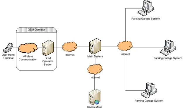
Parking Spot Finder (PSF) system is a combination of several sub-systems. PSF contains lots of functionalities such as sending SMS or communicating with garage systems which are located on every garage spot which are registered to system. PSF is not a stand-alone application. Figure 3.1 shows general structure of PSF system and its sub systems.
Figure 3.1 PSF system General Structure
As seen in the Figure 3.1, PSF system has sub-systems on distributed locations. There are internet connections between all of them. Every part of this system has individual jobs. System accomplishes its’ duty with successful work of all these parts.
6
3.1 GSM OPERATOR
GSM Operator is both start and end point of this system. Users send their requests using SMS. SMS exchange is made by GSM Operator. GSM Operator gets SMS from user and forwards it to another part of PSF system. After operations, responses are prepared and transferred to users by GSM Operator as SMS.
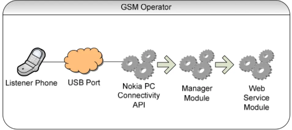
Figure 3.2 GSM Operator System
GSM Operator System has modules. Figure 3.2 shows us structure of GSM Operator System. First component of this system is listener phone which establishes SMS transportation with real GSM infrastructure such as TURKCELL or Vodafone. This phone is connected to server via USB Port. The other communication component of this system is web service module. This module establishes communication between Main Module. Heart of this GSM Operator System is Manager Module. Manager Module waits for incoming SMS. When SMS is received, Manager Module contacts with phone using Nokia PC Connectivity API that is explained in Chapter 4.5. When SMS is transferred from phone to Manager Module, some extra operations are done such as logging. After that, it is sent to Main System using Web Service Module. In contradiction, when Main System is needed to send an SMS to user, SMS is received by Web Service Module. It is transferred to Manager Module. After that, Manager Module sends this SMS to phone using Nokia PC Connectivity API. Finally, phone sends this SMS to user.
7
Actually this module was developed only for simulation of system. In real world, PSF doesn’t need a GSM Operator Module. Because there are already GSM Corporations which provides SMS services for third party companies or associations. Owing to these services these third party companies are able to exchange SMS between their users. These services are based on web services. Web services technology is explained in Chapter 4.3. In addition to that, GSM Operators are able to find out users locations. They have ability to send latitude and longitude of phone and this information can also be sent to third party via web services. PSF will use these services to exchange SMS with users and get users’ locations. Knowing this SMS services and because of being necessary to make deal with Operators to be able to use these services, this module is developed for only simulation purpose. Structure is very similar to real world applications. When this project is used in real world, it will be very easy to implement real GSM Operator Web Service structure owing to Web Services features.
3.2 GOOGLEMAPS
GoogleMaps is a Google service which provides featured mapping service. Detailed information about it is explained in Chapter 4.4. GoogleMaps service has lots of features. PSF system uses map view and distance calculation of this service. This service is an open service, so everyone can use it in their applications. GoogleMaps has not any client component. It can only be used via internet through a web page. Web page uses JavaScript functions to call relevant functions of GoogleMaps and results are received in same way.
3.3 PARKING GARAGE SYSTEM
Parking Garage System can be called as a data farm of this project. These sub-systems are located on garages and they keep these garages’ information such as full/empty spot numbers. When PSF receives a request, PSF makes a connection with them and gets
8
full/empty numbers. On the other hand, when a reservation request is received, PSF calls relevant function and makes this system to reserve.
Parking garage systems are stand-alone systems and their number is changeable. They do not depend on PSF system. They are individual software of Garage lots. PSF has the same number of parking garage systems as number of included garages in PSF system.
If a garage lot wants to join PSF system, there are some necessary needs. First of all, it has to have software which is able to store full/empty spots number in real time. Second one, this application has to have a stable internet connection. Third one, this application has to support reservation system. Fourth and the last one, there have to be a development on this application which enables communication with PSF system via web service. This is very easy and cheap development. Because almost every platform supports web service technology, whatever garage system’s development language, web services can be implemented easily.
Figure 3.3 Parking Garage System
PSF system is interested in only communication part of Parking Garage System. As it is said before, Parking Garage Systems can be very different, complex applications. However parking garage systems are developed, there must be same communication structure on all of them. Figure 3.3 shows a sample parking garage system. Web service module establishes a connection with PSF Main System. It provides stable and reliable data exchange over
9
internet using web service technology. Manager module is responsible of data transfer between parking garage module and web service module. Parking garage module is real garage applications which executes all operations relevant to garage. As it is seen in this figure, web service module and manager module are the parts to be developed before garage joins the PSF system.
3.4 MAIN SYSTEM
Main system is both heart and brain of PSF system. It is located on center. Every data, every request and response is passed from here. When there is a problem in it, PSF is down. With this aspect, it resembles to heart. On the other hand, it receives and evaluates requests, gives decisions and executes operations. It also orchestrates all sub-systems, organizes data transfers. These features make it the brain of PSF at the same time.
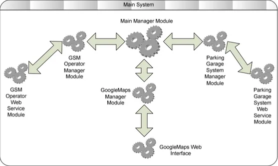
Figure 3.4 Main System
Figure 3.4 shows components of Main system. Main system can be separated into modules easily because there are specialized duties for every module.
10
GSM Operator Web Service Module is a communication module which provides data exchange between Main System and GSM Operator System. This module connects to GSM Operator system and get or send data using web service technology.
GSM Operator Manager Module is a connection manager module. This manager module decides when data will send to or when data will be get from GSM Operator System. It gets or sends data, executes some extra operations here such as logging. After operations are done, manager module transfers data to either web service module or main system module.
GoogleMaps Web Interface is a web page. GoogleMaps Service is a JavaScript based service. Because JavaScript is a web technology, there have to be a web page which is able to use GoogleMaps Service functionalities. This is why main system needs such a web page. This web page includes necessary controls, JavaScript codes and a map which shows garages. This module provides a communication line between PSF system and GoogleMaps Service.
GoogleMaps Manager Module is responsible for exchanging data between GoogleMaps Service and PSF Main System. To accomplish this duty, this manager module modifies GoogleMaps Web Interface and invokes this interface’s functions. This manager module has control over interface. It can modify web interface depending on needs. Data transfer to\from GoogleMaps Service can be accomplished by invoking of JavaScript functions of web interface.
Parking Garage System Web Service Module is responsible for communication between related Parking Garage System and Main System. As it is said before, there can be various Parking Garage Systems in PSF. But one web service module is enough to communicate each of them. Every Parking Garage System has web service with same structure but web service URL. And this module can easily set a connection with them just changing URL of remote service in its connection configuration.
11
Parking Garage System Manager Module executes logical, necessary operations and prepares Parking Garage System Web Service Module before data exchanges. When Main Manager Module needs to get data from Garage Systems, request is sent to Manager Module. Manager Module connects every garage system changing configurations of Web Service module and collects data from them. After data is received, Manager Module converts it to a readable data by Main Manager Module and forwards it.
Main Manager module is the maestro of Main System. Every request is received here. When a request is received here, this module executes some operations over this request and decides what will be done next. Another manager might be called and this manager’s response might be sent back or response might be created by this module and it might be sent back, or multiple managers might be called. Multiple responses might be gathered and new response is created from them. Then this response is sent back. This module works as decision-maker. At the same time this module has to arrange data traffic between managers.
12
4.
INFRASTRUCTURE
Parking Spot Finder (PSF) system is combination of different sub-systems. Each of systems has different duty in overall system. While these sub systems execute their jobs, they use different infrastructures. In addition to individual structures, they also need a common communication structure.
Web services technology provides communication structures. GoogleMaps API service provides locating users and showing map. System accomplishes SMS traffic using Nokia PC Connectivity API. And finally, all these components are developed in .NET Framework 2.0.
4.1 .NET FRAMEWORK
The .NET Framework is a new environment for next generation applications and XML Web services. It supports building and running many various technologies on Microsoft based platforms. Microsoft first announced the .NET in July 2000. The first version of this platform is .NET 1.0. Microsoft has released many versions so far. The recent stable version is .NET 3.5. .NET 4.0 beta version was released in 2009.
The .NET Framework is designed to fulfill some objectives as it is said in .Net Framework
Conceptual Overview article in Microsoft Web Site (2005). This platform provides
consistent object oriented programming language. It enables object codes to be used locally or remotely. It makes application deployment easy and reliable. It provides an environment for safe execution of code. This environment also helps to eliminate performance problems. Another objective is providing a development environment that makes developer experience consistent across widely varying types of applications, such as Web-based applications and Windows- based applications.
13
The .NET Framework is consists of two main components. First one is the common language runtime (CLR). The other one is .NET Framework class library. CLR can be thought as an agent that is responsible for managing execution of code at run time. CLR organizes core services such as memory management, thread management and remoting operations. CLR enables secure code execution and prevents unwanted conditions in communication between code and core services. Beside managing code execution is very important, code development environment is also important. The class library of the .NET Framework provides comprehensive object-oriented collection of reusable types that can be used to develop applications ranging from command line applications to Web Based applications.
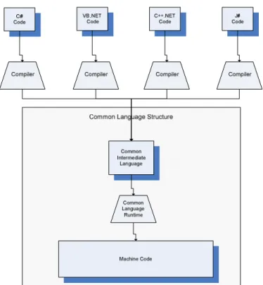
The .NET Framework supports many different programming languages. More than 20 languages are supported by framework. But Microsoft declared that main language of .NET framework is C#. The .NET Framework accomplishes this support owing to its architecture. This architecture can be seen in Figure 4.1.
14
Figure 4.1 the .NET Framework Supports Different Languages
Every code that is developed on .NET Framework is converted into Common Intermediate Language (CIL). It is also called as Microsoft Intermediate Language (MSIL). CIL is a common language for the .NET Framework. This provides language and platform independent programming. A code that developed by supported language is converted into CIL language. After that, this converted code is compiled with platform specific CLR. And CLR converts this code into machine readable code which can be executed by current platform.
PSF Main system is developed on .NET Framework. .NET 2.0 is used to develop all applications. And ASP.NET 2.0 is used to develop web based applications. Programming language is C# 2.0 is used in all code developments.
15
4.2 DATABASE
Data storage is one of the most important parts of software systems. There are many different ways to store data. Each one has some powerful aspects to others. Sample text document or XML documents can be used as storage. But these sample methods are far away to meet applications’ needs. Database systems are generally used for storage. Database systems specialize on data storage. They have different and individual data storage and data access algorithms. They do not keep data as text documents or XML documents. The leading database systems are SQL Server (Microsoft) and Oracle (Sun)
SQL Server is used in PSF system. PSF system needs to keep data. There are many data exchanges. Also, user data must be kept to be reused. Because of SQL Server is more efficient with .NET Framework, it is used in PSF system. SQL Server 2005 version is chosen, because .NET Framework 2.0 is widely used with SQL Server 2005. They work together stable and reliably.
4.3 WEB SERVICES
Reaching data is always one of the most important subjects of IT sector. If a computer does not have any connection with rest of the world, it is useless. To achieve fast data access, engineers set up network systems. Firstly, networks are limited. There were few computers in networks. But after years, networks’ popularity has increased. People could reach data that was on another computer, from their computer easily. Engineers, who saw those need and improvement, set up very large networks. They set up Internet. People could reach data from the far end of the world easily owing to Internet. It was very big improvement in reaching data. But this was human centered technology. A person sends requests from his computer to server, and server sends him a response. Person reads response and owns data. Improvement in network sector brought out a new need. Applications must have been able to talk with each other without a human control over network.
16
It is easy to set communication between applications which are on the same location. But the problems come into picture when communication on network or internet is subject. If applications are on the same machine, there are several simple ways to connect these applications. But data is on the rest of the world. Applications need to reach data which are on the Internet. When it was getting big need of communication over internet, software vendor began to work on new technologies new standards to accomplish making data transfer over internet reliably and easy. They developed several technologies, standards and protocols. Some of these standards are DCOM, CORBA and Java RMI.
Because it was very early in this technology, there weren’t global standards. So vendors used their own standards in their software. These standards provided applications to communicate over internet. But, in order to communicate, applications must have used same standards, must have been on same platform or product of same vendor. Otherwise extra developments were needed. These developments were very difficult and there were lots of problems because every platform had individual features.
At this point Web Service technology came on to scene. It is very simple technology. It decreased development load. Beside its’ simplicity, data transfer can be made faster, easily and more reliably. Data transfer method is another powerful aspect of Web services. Web service technology supports object transfer instead of only data transfer. It makes lots of thing easier for software developer. Because of its power, all big vendors accepted to use it in their products. Owing to this, web service gained another significant feature. That is communication between different platforms. Web service technology becomes the one of the most popular technologies of today’s internet world.
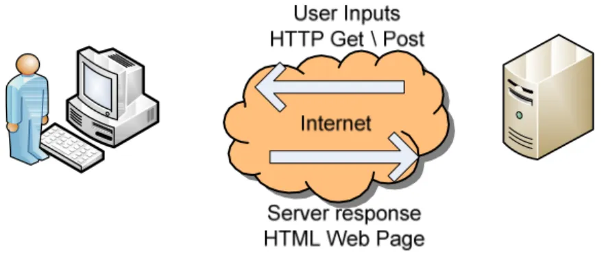
Web services are not human centered technology. For example, web pages are human centered. People open web pages read something, enter inputs and get outputs. All transactions are started by human or ended by human. HTML web pages are used and
17
HTTP Get\Post methods are used for communications. Users always see an HTML web page on screen and send requests using HTTP Get\Post methods.
Figure 4.2 Internet is Human Centered
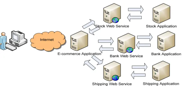
On the other hand, for example there is an e-commerce web page. When a person wants to buy a product, this application must ask stock applications if this product is on stocks or not. After getting stock information, it is showed user. When user clicked buy button, this e-commerce applications must communicate between bank and must get paid information, after successful paid this applications must talk with shipping system and must give shipping information and product information to it. As it is seen while user is looking at one page and clicking few buttons, there are lots of transactions and communication at background.
18
Figure 4.3 Web Services are Application Centered
Web services are located between these applications in this scenario. Outputs generated by web services are not for end user and are not showed to user. They are consumed and used to generate other outputs. Web services are designed for applications. It is application centered technology. (Cerami 2002)
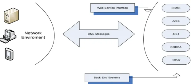
Web service is application centered technology. On the other hand, it is not important features of applications which are located sides of communication. Web services use common protocols. Every vendor supports these protocols. Web service technology uses Extensible Markup Language (XML) to represent data. The Simple Object Access Protocol (SOAP) provides the semantics for data exchange and the Web Services Description Language (WSDL) provides a mechanism to describe the capabilities of web service.
19
Figure 4.4 Web Services Use XML to Represent Data
Many applications can connect web service and get data. Changes in connected applications number are not important. In old technologies, it requires extra development in software. There is not any need of development in web services. Client application is developed due to description of web service. And communication is ready.
Developing web services is also very simple. Contradiction to old technologies web service technology has simple architecture. It uses XML standards. And XML has very simple syntax. Addition to, most of software vendors develop their own web service support tools or integrated web service mechanisms to their own platforms. This simplicity prevents developers from errors and bugs.
Data transfer is very important in computer systems. But at the same time security is another very important subject. There is not any new mechanism need to secure web services. Existing security mechanisms are sufficient. If there is a secure transport available between web services such as SSL or TLS, there is not any extra need for web service security. If there is not secure transport, many mechanisms can be applied. The general web services security model supports several more specific security models, such as identity-based authorization, access control lists, and capabilities-identity-based authorization. It allows the
20
use of existing technologies such as X.509 public-key certificates, XML-based tokens, Kerberos shared-secret tickets, and password digests. The general model is sufficient to construct systems that use more sophisticated approaches for higher-level key exchange, authentication, policy-based access control, auditing, and complex trust relationships. Proxies and relay services may also be used (Cabrera, Kurt, Box 2004).
PSF system is combination of many sub systems. These sub system are located on different location. Web service technology provides them exchange data over internet easily, reliably and safely. Web services are used extremely in PSF project.
4.3.1 Extensible Markup Language (XML)
XML, the extensible markup language, is a W3C-endorsed standard for document markup. It defines a generic syntax used to mark up data with simple human-readable tags. In contradiction to HTML, tags are not certain. It is some rules to give a name to tags. Any string which satisfies these rules can be given to tags. It is very flexible markup language. This standard format provides that XML document can be used in various technologies. Data storage, data transfer or individual techniques.
21
XML is very flexible but at the same time it is also very strict markup language. All documents must satisfy syntax rules. Otherwise XML processors reject documents. This provides interoperability. All platforms, all XML parsers can easily read XML documents which are created by obeying basic rules.
Sometimes, there is a need to work on same structure of XML document. For example, an XML document is being transferred from an application to another. There must be some rules for tags arrangement in XML document. Writer application must create XML document by applying these rules, and reader application must read XML document and reach data by also using these rules. XML supports this mechanism. It is called XML Schema. Developers first create schema and develop their applications that will read or write XML document with this document schema. Result of this, application can exchange XML documents easily.
Web services are based on XML structure, because all data transfer, data descriptions, and data exchange rules are on XML documents. And web services are not platform or software language dependent owing to XML structure.
4.3.2 Simple Object Access Protocol (SOAP)
Web service technology accomplishes data exchange using Simple Object Access Protocol (SOAP). SOAP is a mechanism that provides structured and typed data transfer between distributed environments. SOAP message is an envelope of data that is sent to client or Web services over HTTP. (Snell, Tidwell and Kulchenko 2002)
Any software that sends or receive SOAP message is called SOAP node. The node that creates message and sends over HTTP is called original sender. The final node which receives message and processes it, is called the ultimate receiver. Any node between original sender and ultimate receiver is called intermediary.
22
SOAP is one-way communication model that ensures that message is transferred from sender to receiver. Client sends a request messages to web service, web service processes it and sends response.
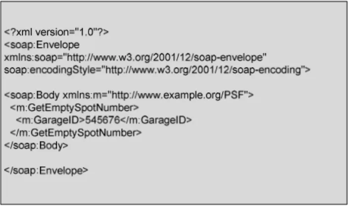
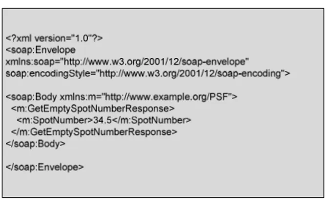
SAOP message is an XML message which contains data and some SOAP tags. Because SOAP message structure based on XML, SOAP message can be transmitted between various platforms and applications. Any XML message can be SOAP message by adding some specific SOAP tags (Wolter 2001). That means SOAP messages are just an XML document. They do not have any special functionality. Figure 4.6 and 4.7 shows sample SOAP request and response messages.
23
Figure 4.7 Sample SOAP Response Message
SOAP message contains three elements. There are Envelope, header, and body elements. Envelope is the root element. Envelope contains header and body elements. Header element is an optional element. Header element can be used for variety of task, from routing messages to the proper recipient to ensuring that a recipient understands a particular request before attempting to process the message. Header element can be read by sender receiver or intermediary nodes. But body nodes can be read by only receiver. How SOAP receiver or sender processors consume information in body node, is described in WSDL documents. WSDL is explained in next chapter.
Figure 4.8 Software Vendor has Their Own SOAP Processors
SOAP message must be created by receiver or sender. Because SOAP has a Universal standard, software vendors have their own SOAP processors. Developers do not have to focus on SOAP structure. These processors get SOAP messages and convert them into more meaningful structures for developers.
24
4.3.3 Web Services Description Language (WSDL)
Web services use Web Services Description Language (WSDL) to create an XML document that describes them. WSDL documents are contracts between service requestors and service providers. WSDL documents are based on XML and XML schema. This provides WSDL documents to be platform – language independent. A WSDL document created with any platform can be used by any other. Developer who develops a client to communicate with web service gets this WSDL documents and he learns what functionality this web service has, where this web service and which types are used in this web service functions. A complete WSDL definition contains all of the information necessary for service requestor to invoke any function of web service. WSDL document describes four critical pieces of data
- All public functions of Web service
- Data type definitions which are used in request or response messages. - Binding information about the transport protocol to be used
- Address information of service.
WSDL is an XML grammar for describing web services. This specification is divided into six major elements.
definitions is root element. This element contains name of web services, namespaces and all
25
Figure 4.9 Definitions Tag Example
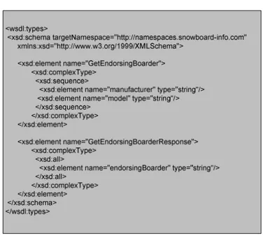
types contains all external data type definitions which are used in request or response
26
Figure 4.10 Types Tag Example
message contains one-way message description that is response or request message. It
describes message name, and contains zero or more sub-elements which are message parameters or return values.
Figure 4.11 Message Tag Example
portType is the most important WSDL element. It defines which operation can be
performed and the messages that are involved. This element defines connection point of web service. Each operation elements can be compared to a function in a traditional programming language.
27
Figure 4.12 PortType Tag Example
binding describes how data package goes on the wire. Message format and protocols is
defined here. WSDL specification uses SOAP. So there is SOAP-specific information here.
Figure 4.13 Binding Tag Example
4.4 GOOGLEMAPS API
GoogleMaps is a Google service that provides powerful mapping technology. GoogleMaps provides satellite images or map data. And also GoogleMaps provides location information, calculation of distance between two points, and direction information from one point to another point using roads etc.
28
GoogleMaps API is developed for developments who want to use GoogleMaps features for their individual applications. GoogleMaps API is a JavaScript based service (http://code.google.com/apis/maps/ 2009). There are list of functions and objects of this API.
PSF need a distance calculation of two points given on a map. In this part, GoogleMaps is a solution. GoogleMaps API is used in developing in distance calculation module.
4.5 NOKIA PC CONNECTIVTY API
Nokia PC Connectivity Solution is described in Tools and SDKs for Mobile Software
Development (2009) page of Nokia web site, as a service of Nokia Corporation for
developers who want to develop an application that connect and use features of Nokia mobile phones. Developer can create their own applications that can interact with mobile phones.
Developer creates their applications using Nokia PC Connectivity API. This API is a part of Connectivity Solution. This API is a DLL file. This DLL file has many functions and objects that provide developers to connect and send data to phone or get data from mobile phone. This API has different versions for different software languages.
There is a GSM Operator simulation in PSF system. SMS messages must be sent or received. This GSM Operator module used Nokia PC Connectivity API to accomplish SMS exchange.
29
5.
IMPLEMENTATION DETAILS
PSF system is based on requests and responses. User sends a request and invokes PSF system. After request receives, data flow begins in PSF system. It continues with creating new requests for other services or applications such as GoogleMaps or Garage System. After these components send response, data collection begins from these responses. After collecting data is ended, new response is created and it is sent to user. Data travels in PSF system via requests or response structures.
PSF system components have some differences and some similarities in their architectures. They use different services and applications to collect or access data from outside sources. But they use database to store data and they need to get data from database. This architecture is same for all of them. In addition to that, they use same communication technology.
5.1 DATA FLOW
Data flow diagram is showed in Figure 5.1. This diagram shows us which operations are done while PSF accomplishes its’ aim.
30 User sends information SMS GSM Operator receives SMS from user PSF gets SMS from GSM Operator PSF decides information or reservation SMS coordinate information of user is get
nearest garage lists is found out from registered
garages
Full/empty spot numbers are collected from nearest
garages distance between user and
each of garages is calculated using
GoogleMaps
best result is calculated and information of this garage is sent back to
GSM Operator GSM Operator Receives SMS from PSF and sends it to user User receives SMS User sends reservation SMS
Which garage is sent to user last is found
out
Full/empty spot number is checked
Reservation request is sent to garage system
Reservation information and ticket id included SMS
is forwarded to GSM Operator
İf there is not any empty spot, an error message is created
This error message is forwarded to GSM
Operator
Figure 5.1 Data Flow Diagram of PSF
As it is seen in Figure 5.1 data flow begins with user’s request. User can request in two different ways. First one, user sends an SMS that includes information requests. That
31
means, user wants to know which garage is the nearest to him and what it is information such as empty spot number or how far it is. Second way, user sends an SMS that includes reservation requests. User can only send a reservation SMS after he receives an information SMS response. After he receives an information SMS response, he can replies it and sends reservation request SMS. This SMS starts a flow which provides a reservation for this user. These two request SMS are showed in Figure 5.2 and 5.3.
SPOT
32 RESERVE
Figure 5.3 Reservation Request SMS
There are two keywords for PSF system. If user wants to get information, he must write “SPOT” and send it to a number that is specialized for PSF system by GSM Operators. If user wants to reserve a spot then, he must write “RESERVE” and send it to PSF number. After SMS is sent by user and received by PSF system, the first step is completed for PSF data flow.
After SMS is received by PSF system, the main operations are started. First operation is to decide which SMS type this SMS is. There are two types of SMS in PSF system. First one is Information Request SMS and second one is Reservation Request SMS. This decision is made and related flow begins.
Getting information flow is longest and most complex flow in PSF system. If user requests information, then PSF requests user’s coordinates from GSM Operator. GSM operator sends latitude and longitude information of user. After that, PSF system creates a list from nearest garages. While this list is created, distance between coordinates is used (as the crow flies). Registered garages coordinates are kept in database. PSF system gets the top five nearest garages which have nearest coordinates to user. After this list is created, for every garage, garage coordinates and user coordinates are sent to GoogleMaps Service and real
33
distance information between user and garage is calculated. GoogleMaps calculates real distance considering real world factors such as roads lengths, or road direction etc. After real distances are calculated, PSF system starts to get information from Garage Spots. Full/empty spot numbers of these five garages are collected. When collection completed, an algorithm is applied to them. This algorithm calculates a score using distance and full/empty spot number. This algorithm aims to find best result for user. Sometimes, nearest garage spot is not best result or more empty spot number is not enough. This algorithm balances these two factors. After these points are calculated, best garage is located at the top of list. Response SMS that includes this garage spot’s information, is sent to GSM Operator. Then it is received to user. This response SMS is showed in Figure 5.4
Figure 5.4 Information Response SMS
After above SMS is received to user, he can reply this SMS with “RESERVE” keyword and he starts reservation flow. As soon as reservation request is received by PSF system, the last sent information SMS content to this user is searched in database. When information SMS is sent, every necessary part of SMS is stored in database such as garage spot id. After SMS content that includes garage spot id is found, communication between related garage spot is set up. Full/empty spot count is requested from this garage spot. If
34
there are empty spots, then reservation request is sent to this garage spot. On the other hand, if there is not any empty spot, an error message is sent back to user. Reservation request that is sent to garage spot includes user phone number. With this information, garage spot system reserves a spot for this user and sends back a reservation id and spot id. This spot is reserved for this user for a specific time. After PSF gets reservation response from garage system, it generates an SMS that includes this reservation information and sends it back to user. This information is showed in Figure 5.5. This SMS is the end of this flow.
35
6.
ARCHITECTURE
PSF system applies multi-tier architecture. Every component are developed obeying this architecture rules. Multi-tier architecture tries to separate presentation parts and data access parts in software. Three-tier architecture is shown in Figure 6.1
Figure 6.1 Three-Tier Architecture
Three-tier architecture contains Presentation layer, Data Access layer and Data layer. Presentation layer is the layer where data is ready to be shown or transfered to another application or where application gets inputs. Data Access layer is a layer where data
36
requests and responses pass through with controls or extra operations. Data layer is the bottom layer where data is requested from data store. This multi-tier architecture provides extra security, easy maintenance, modularity etc. It is one of the most popular design patterns of the software world.
PSF system architecture can be analyzed in three parts. First part is GSM Operator part. As it is said before in real world PSF does not need a GSM Operator component but it is developed for simulation purpose in PSF system. Because this is one of the main components of PSF, it is necessary to explain. Second part is Parking Garage System. Parking Garage Systems are also external components which are located on Garage lots. But the communication part must be the same at all. There are sample Parking Garage Systems which are developed for simulation. This communication architecture and sample parking system architecture can be analyzed owing to these sample applications. The third part is Main System it is the core component of PSF.
6.1 GSM OPERATOR SYSTEM
GSM Operator System is a windows application with a web service. It is also called SMSGateway in codes. Windows application checks phone if there is a new SMS or not. At the same time, this application checks database if there is an SMS that will be sent to user. When Main System asks if there is a new SMS coming from user or sends a new SMS to be sent to user, web service is used. Web service checks database and returns recorded SMS coming from user. If Main System transfers a new SMS to send user, then web service saves this SMS to database.
37
Figure 6.2 GSM Operator System Windows Application
Windows application interface can be seen in Figure 6.2. There are some controls on this interface which show notifications about what are happening at background. Notification panel shows connection status with Nokia phone. Watch Log part shows incoming and outgoing SMS contents.
This windows application uses Nokia phone to get or send SMS. PC Connectivity API is used to connect to this phone. Windows application starts a thread when its initializations finished. This thread asks if there is a new SMS in phone in periods. If there is a new SMS in the phone, thread moves this SMS from phone to database with converting its’ own object. Thread saves this data to table which name is SMSInbox. On the other hand, while thread asking to phone new SMS, at the same time this thread checks database if there is a new SMS that is saved by web service which will be sent to user. If there is a record, thread gets this data from table which name is SMSOutbox and saves this SMS in phone’s outgoing folder. When save operation is completed, phone sends this SMS automatically.
38
Figure 6.3 GSM Operator System Database Tables
Web service is used to transfer data between main system and GSM Operator database tables. Web service is a passive application. When something is asked from it, then it does necessary action. Its’ functions are shown in Figure 6.4.
Figure 6.4 GSM Operator System (SMSGateWay) Web Service
Main system calls GetIncomingSMSList and this web service collects data from SMSInbox table and sends back. On the other hand, if main system calls SetOutgoingSMS function and sends data, this service saves this data in SMSInbox.
This GSM Operator application applies three-tier architecture same as the other components of PSF system. This windows application and web service are located on presentation layer. Data access and data layers include some other classes. These classes are shown in Figure 6.5 and Figure 6.6
39
Figure 6.5 Data Access Layer in GSM Operator System
SMSMessageBUS class can be named as data access layer. All operations are done here. Presentation layer has to call one of the functions from here to do operations on database. SMSMessageEntity is an entity class that means a class which structure is the same as the database table structure. It is used for creating an object which enables easy data transfers between functions, layers or objects.
40
Figure 6.6 Data Layer in GSM Operator System
SqlHelper class is the data layer class of GSM Operator System. SqlHelper is an open project of Microsoft. It enables to run query over database. This is the last layer before database. All PSF systems use SqlHelper as a data layer. Every operation over database can easily be executed using this class.
6.2 PARKING GARAGE SYSTEM
Parking garage system can be various types of applications but they have to have a standard communication component with PSF Main System. This communication part has to be a web service which has to supply main system needs. Main system uses standard functions,
41
so this web service has to have these functions. In simulation project, there are four garage systems to understand this structure easily. They are windows applications with web services. Windows application interface is shown in Figure 6.7. This is a garage map which shows empty spots in green, full spots in red, reserved in orange and building entrance in brown. Also empty numbers, full numbers, reserved numbers and total spot numbers are shown in status bar.
Figure 6.7 Parking Garage System Windows Application
This application simulates a garage system. There is an infinite loop in this application. It gets status of spots from database and draws this interface. At the same time spots status is changed from empty to full or full to empty in periodically and randomly. This provides a simulation of real garage system. When web service reservation function is called and reservation is made successfully, this windows application converts reserved spots’ color to orange and does not change its’ status until reservation time is over or user reaches this spot.
42
Figure 6.8 Parking Garage System Database Structure
Database structure used in Parking Garage System is shown in Figure 6.8. Spots table contains this garage’s spots data. When a spot’s status is changed its’ status column value also changes. Reservation table holds data of reservation information. When there is a reservation request, this is saved in this table. LogTable is a system table where software exceptions, problems are recorded.
Figure 6.9 Parking Garage System Web Service
The most important component for PSF system is web service part. Mandatory functions are listed in Figure 6.9 These functions are called by Main System. These functions have to be in web services of Garage Systems. PSF Main system gets number of empty spot number by calling GetEmptySpotCount function. It returns empty spot numbers collecting data from database. GetSpotCount function returns total spot number of this garage. GetSpotInfo functions returns information of selected spot and finally ReserveSpot
43
function operates reservation by inserting related data to Reservation table and changing status of this spot record in Spots table.
Web service and windows application is presentation layer in this system. Data layer is the same structure which is used in GSM Operator System. On the other hand, data access layer is different here. Figure 6.10 shows entity class structures and 6.11 data access layer class structures.
Figure 6.10 Entity Class Structures of PSF Garage Systems
Entity classes are used to create entity objects. These entity objects are very usable for data transfer between layers, functions or even applications. Entity class structure mostly resembles to database table for which entity class is written. Sometimes there are some
44
extra fields or functions. PSF Garage system has ReservationEntity, ReservationTicket, SpotsEntity and SpotInfoResponseEntity entity classes. ReservationEntity is created for Reservation table operations. ReservationTicket class is used to create an object which holds data of result of reservation operations. SpotsEntity class has the same structure with database table. Object created from this class is used everywhere that is related to this database table. SpotInfoResponseEntity class is used to create object which holds some information of spots. This object is used to carry data between layers and applications such as between web service and main system.
Figure 6.11 Data Access Layer in PSF Garage Systems
PSF Garage Systems’ data access layer contains three classes. These are BaseBUS, RandomizeSpots and LogManager. In fact, BaseBUS is the actual data access layer class. BaseBUS class is created to access data layers and make data layer execute database operations. RandomizeSpots class is used to execute randomize operations. But while it is executing randomize operations, it selects or updates some value in database. Because of these database operations this class is located at data access layer. LogManager class is a class where logging operations are collected. LogManager class also executes database operations such as log inserts. Because of this, it is also located in data access layer.
45
6.3 MAIN SYSTEM
Main system is combination of a windows application and a web page. This web page is embedded into windows application. Windows application holds all controls of this web page. This application communicates with other parts of PSF system using web services. But it does not have any web services. It only uses other component’s web services. Embedded web page is a .NET Active Server Page (ASPX) web page. This web page is used to communicate between GoogleMaps. Figure 5.12 shows this windows application while it is on work.
Figure 6.12 PSF Main System Windows Application
46
Web page area is an ASPX page. This page contains two controls. First one is GoogleMaps control and the other one is Refresh View button control. Before application view in screen, windows application modifies this web page and sets some parameters. After initialization is completed in windows application, then another initialization starts at the web page side. Related parameters are sent to GoogleMaps service and this service draws a map which includes red labels that show registered garage locations. When a request for garage information is received, windows application sets some parameters and invokes JavaScript functions of web page. After that, web page sends data to GoogleMaps service and service draws another map such as on the Figure 6.12. This shows garage locations, user’s location and also shortest road directions between user and all garages in blue color. At the same time, distances between user and garages are sent back by GoogleMaps service. After these data responses are received, windows application gets these data from web page and continues to do next works. The second control in this area is refresh button. This button refreshes map view.
The other area in this windows application is log screen. Log screen contains text that shows which operation is being executed, were executed or some other notifications. Log screen control in Figure 6.12 contains three line texts which are about receiving SMS, processing SMS and sending SMS. These messages order is descending due to time.
Beside this user interface, core operations are executed background. This application has two threads. These threads are running for SMS operations and Garage System operations. Classes which are used as threads are shown in Figure 6.13.
47
Figure 6.13 Thread Classes in Main System
These thread classes are derived from BaseHandler class and named SMSGateWayHandler and CentralHandler. SMSGateWayHandler is a thread which is responsible for getting unread SMS from GSM Operator System. CentralHandler is responsible for everything else.
SMSGateWayHandler thread collects unread SMS from GSM Operator System. When this thread starts to run calling RunThread function, it begins to ask GSM Operator system if there is any unread SMS in its’ database periodically. Thread asks this question using GSM Operator web service. If there is unread SMS, then web service returns SMS list. Thanks to web service technology, classes that are created in GSM Operator System such as SMSMessageEntity class is able to be used in Main System. After these unread SMS receives, SMSGateWayHandler thread converts this object into new entity type of Main
48
System using ConvertEntities and SetLocation functions. After conversation, this new entity is sent to data access layer to be saved into main system database. Beside thread functions, this class contains another function which is called SendSMSToCustomer. This function is used to send SMS as it can be understood by its name. Another class can use this function to send SMS to customer. For example CentralHandler thread uses this function a lot. This function does not belong to thread. But it is talking to GSM Operator System, so it is located here.
CentralHandler thread has heavy load. It is responsible for almost everything in main system. RunThread function is invoked and this thread begins to run. First step for this thread is, evaluating unread SMS. It asks unread and requesting information SMS list from data access layer. After this SMS list is received, nearest garages are found out by web page. When nearest garage list is created, thread gets empty/full numbers from these garages by calling ConnectGarageAndGetSpotInfo function. The next step is, calculating garage point by calling GetDistanceCalculationScore of CommonHelper class. Garages are listed by their scores and garage with the best score is chosen and best garage object is converted into SMSMessageEntity of main system. After that conversion, this SMSMessageEntity is sent to GenerateLocationReply function. This function returns an SMS text. Then this text is sent to SendSMSToCustomer function of SMSGateWayHandler. Information SMS is sent to customer. The next step is, update and insert operations for CentralHandler thread. After this SMS is sent, this record’s status is updated and this SMS’s content is inserted into database. When evaluation of information request SMS is completed, it is time to evaluate reservation request SMS. Thread asks data access layer whether there is any SMS which is waiting for reservation. If data access layer returns any SMS, reservation operations begin. Firstly, thread gets SMS content data from database. This is the last information SMS that user received. SMS content data contains garage information where user wants to make reservation. This SMS content also contains information sent date. Because reservation has to be made after information SMS and Garage Spots’ status can be changed fast, reservation SMS must be sent in limited time. Thread checks if difference between reservation SMS time and information sent date is out
49
of time limitation. After this validation is passed successfully, empty/full information of garage is checked calling ConnectGarageAndGetSpotInfo function. If there are empty spots, reservation is made by calling ReserveSpot function and reservation ticket is created. ReserveSpot function connects to GarageSpot web service and call ReserveSpot function. Then, it returns the result of web service method. Sending reservation response SMS is the next step. If sending operations do not have any exception, this SMS record is updated in the database. This is the last step of life circles of thread. After that threads begin to run from the beginning.
These two thread classes are the basic classes, but there are also some helper classes. These helper classes are shown in Figure 6.14.