This content has been downloaded from IOPscience. Please scroll down to see the full text.
Download details:
IP Address: 212.174.144.130
This content was downloaded on 11/11/2015 at 12:52
Please note that terms and conditions apply.
The ATLAS TRT Barrel Detector
View the table of contents for this issue, or go to the journal homepage for more 2008 JINST 3 P02014
(http://iopscience.iop.org/1748-0221/3/02/P02014)
2008 JINST 3 P02014
PUBLISHED BYINSTITUTE OFPHYSICSPUBLISHING ANDSISSARECEIVED: December 21, 2007
REVISED: February 1, 2008
ACCEPTED: February 5, 2008
PUBLISHED: February 29, 2008
The ATLAS TRT Barrel Detector
The ATLAS TRT collaboration
E. Abat,a† T.N. Addy,j T.P.A. Åkesson,mJ. Alison,uF. Anghinolfi,cE. Arik,a†M. Arik,a
G. Atoian,zB. Auerbach,zO.K. Baker,zE. Banas,f S. Baron,cC. Bault,c N. Becerici,a A. Beddall,a1A.J. Beddall,a1J. Bendotti,cD.P. Benjamin,gH. Bertelsen,d A. Bingul,a1
H. Blampey,cA. Bocci,gM. Bochenek,eV.G. Bondarenko,pV. Bychkov,lJ. Callahan,k
M. Capeáns Garrido,c L. Cardiel Sas,c A. Catinaccio,c S.A. Cetin,a2 T. Chandler,z R. Chritin,hP. Cwetanski,k M. Dam,dH. Danielsson,cE. Danilevich,vE. David,c
J. Degenhardt,uB. Di Girolamo ,c F. Dittus,c N. Dixon,cO.B. Dogan,a†
B.A. Dolgoshein,pN. Dressnandt,uC. Driouchi,dW.L. Ebenstein,gP. Eerola,m U. Egede,mK. Egorov,k H. Evans,kP. Farthouat,cO.L. Fedin,vA.J. Fowler,g
S. Fratina,uD. Froidevaux,cA. Fry,j P. Gagnon,kI.L. Gavrilenko,oC. Gay,y N. Ghodbane,rJ. Godlewski,cM. Goulette,c I. Gousakov,l N. Grigalashvili,l
Y. Grishkevich,qJ. Grognuz,cZ. Hajduk,f M. Hance,uF. Hansen,d J.B. Hansen,d
P.H. Hansen,dG. Hanson,k3G.A. Hare,uA. Harvey Jr.,j C. Hauviller,cA. High,u W. Hulsbergen,cW. Huta,cV. Issakov,zS. Istin,aV. Jain,kG. Jarlskog,mL. Jeanty,y
V.A. Kantserov,pB. Kaplan,zA.S. Kapliy,uS. Katounine,vF. Kayumov,oP.T. Keener,u
G.D. Kekelidze,l E. Khabarova,lA. Khristachev,v B. Kisielewski,f T.H. Kittelmann,w C. Kline,kE.B. Klinkby,d N.V. Klopov,vB.R. Ko,gT. Koffas,c N.V. Kondratieva,p
S.P. Konovalov,oS. Koperny,eH. Korsmo,mS. Kovalenko,vT.Z. Kowalski,e
K. Krüger,vV. Kramarenko,qL.G. Kudin,vA-C. Le Bihan,v B.C. LeGeyt,uK. Levterov,l P. Lichard,c A. Lindahl,dV. Lisan,l S. Lobastov,l A. Loginov,zC.W. Loh,yS. Lokwitz,z
M.C. Long,jS. Lucas,cA. Lucotte,iF. Luehring,k B. Lundberg,mR. Mackeprang,d
V.P. Maleev,vA. Manara,kM. Mandl,cA.J. Martin,zF.F. Martin,uR. Mashinistov,p G.M. Mayers,uK.W. McFarlane,j V. Mialkovski,l B.M. Mills,yB. Mindur,eV.A. Mitsou,x
J.U. Mjörnmark,mS.V. Morozov,pE. Morris,k S.V. Mouraviev,oA.M. Muir,y A. Munar,u A.V. Nadtochi,vS.Y. Nesterov,vF.M. Newcomer,uN. Nikitin,qO. Novgorodova,o
E.G. Novodvorski,vH. Ogren,k∗S.H. Oh,gS.B. Oleshko,vD. Olivito,uJ. Olszowska,f
W. Ostrowicz,f M.S. Passmore,cS. Patrichev,vJ. Penwell,k F. Perez-Gomez,c V.D. Peshekhonov,lT.C. Petersen,c R. Petti,bA. Placci,c A. Poblaguev,zX. Pons,c
M.J. Price,cO. Røhne,t R.D. Reece,uM.B. Reilly,uC. Rembser,cA. Romaniouk,p
2008 JINST 3 P02014
J. Saxon,uM. Scandurra,k V.A. Schegelsky,vM.I. Scherzer,uM.P. Schmidt,z†
C. Schmitt,c E. Sedykh,vD.M. Seliverstov,vT. Shin,j A. Shmeleva,oS. Sivoklokov,q
S.Yu. Smirnov,pL. Smirnova,qO. Smirnova,mP. Smith,k V.V. Sosnovtsev,p G. Sprachmann,cS. Subramania,kS.I. Suchkov,pV.V. Sulin,oR.R. Szczygiel,f
G. Tartarelli,nE. Thomson,uV.O. Tikhomirov,oP. Tipton,zJ.A. Valls Ferrer,x
R. Van Berg,uV.I. Vassilakopoulos,jL. Vassilieva,oP. Wagner,uR. Wall,zC. Wang,g
D. Whittington,k H.H. Williams,uA. Zhelezkopand K. Zhukovo
aFaculty of Sciences, Department of Physics, Bogazici University, TR - 80815 Bebek-Istanbul,
Turkey
bBrookhaven National Laboratory, Physics Department, Bldg. 510A, Upton, NY 11973, United
States of America
cCERN, CH - 1211 Geneva 23, Switzerland, Switzerland
dNiels Bohr Institute, University of Copenhagen, Blegdamsvej 17, DK - 2100 Kobenhavn 0,
Denmark
eFaculty of Physics and Applied Computer Science of the AGH-University of Science and
Technology, (FPACS, AGH-UST), al. Mickiewicza 30, PL-30059 Cracow, Poland
fThe Henryk Niewodniczanski Institute of Nuclear Physics, Polish Academy of Sciences, ul.
Radzikowskiego 152, PL - 31342 Krakow, Poland
gDuke University, Department of Physics, Durham, NC 27708, United States of America hUniversite de Geneve, Section de Physique, 24 rue Ernest Ansermet, CH - 1211 Geneve 4,
Switzerland
iLaboratoire de Physique Subatomique et de Cosmologie, CNRS-IN2P3, Universite Joseph
Fourier, INPG, 53 avenue des Martyrs, FR - 38026 Grenoble Cedex, France
jHampton University, Department of Physics, Hampton, VA 23668, United States of America kIndiana University, Department of Physics, Swain Hall West, Room 117, 727 East Third St.,
Bloomington, IN 47405-7105, United States of America
lJoint Institute for Nuclear Research, JINR Dubna, RU - 141 980 Moscow Region, Russia mLunds Universitet, Fysiska Institutionen, Box 118, SE - 221 00 Lund, Sweden
nINFN Milano and Università di Milano, Dipartimento di Fisica, via Celoria 16, IT - 20133
Milano, Italy
oP.N. Lebedev Institute of Physics, Academy of Sciences, Leninsky pr. 53, RU - 117 924 Moscow,
Russia
pMoscow Engineering & Physics Institute (MEPhI), Kashirskoe Shosse 31, RU - 115409 Moscow,
Russia
qLomonosov Moscow State University, Skobeltsyn Institute of Nuclear Physics, RU - 119 992
Moscow Lenskie gory 1, Russia
rMax Planck Institut fuer Physik, Postfach 401212, Foehringer Ring 6, DE - 80805 Muenchen,
Germany
sLAL, Univ. Paris-Sud, IN2P3/CNRS, Orsay, France
tDepartment of Physics, University of Oslo, Blindern, NO - 0316 Oslo 3, Norway uUniversity of Pennsylvania, Department of Physics & Astronomy, 209 S. 33rd Street,
Philadelphia, PA 19104, United States of America
2008 JINST 3 P02014
wUniversity of Pittsburgh, Department of Physics and Astronomy, 3941 O’Hara Street, Pittsburgh,PA 15260, United States of America
xInstituto de Física Corpuscular (IFIC), Centro Mixto UVEG-CSIC, Apdo. 22085, ES-46071
Valencia; Dept. Física At., Mol. y Nuclear, Univ. of Valencia and Instituto de Microelectrónica de Barcelona (IMB-CNM-CSIC), 08193 Bellaterra, Barcelona, Spain
yUniversity of British Columbia, Dept of Physics, 6224 Agricultural Road, CA - Vancouver, B.C.
V6T 1Z1, Canada
zYale University, Department of Physics, PO Box 208121, New Haven CT, 06520-8121 , United
States of America
1Currently at Gaziantep University, Turkey 2Currently at Dogus University, Istanbul 3Currently at University of California, Riverside
E-mail: [email protected]
ABSTRACT: The ATLAS TRT barrel is a tracking drift chamber using 52,544 individual tubular drift tubes. It is one part of the ATLAS Inner Detector, which consists of three sub-systems: the pixel detector spanning the radius range 4 to 20 cm, the semiconductor tracker (SCT) from 30 to 52 cm, and the transition radiation tracker (TRT) from 56 to 108 cm. The TRT barrel covers the central pseudo-rapidity region|η| < 1, while the TRT endcaps cover the forward and backward eta
regions. These TRT systems provide a combination of continuous tracking with many measure-ments in individual drift tubes (or straws) and of electron identification based on transition radiation from fibers or foils interleaved between the straws themselves. This paper describes the recently-completed construction of the TRT Barrel detector, including the quality control procedures used in the fabrication of the detector.
KEYWORDS: Particle tracking detectors; Large detector systems for particle and astroparticle physics; Transition radiation detectors; Particle identification methods.
∗Corresponding author.
2008 JINST 3 P02014
Contents
1. Introduction 2
2. TRT Barrel and component specification 4
2.1 Barrel Support System 7
2.2 Shell specification and acceptance 7
2.3 Straw alignment plane (divider) specification and acceptance 9
2.4 Radiator specification and acceptance 9
2.5 HV plates 11
2.5.1 HV feed 11
2.5.2 Thick plate 12
2.5.3 Thin plate 13
2.5.4 Assembly of the HV plate 13
2.5.5 HV stability 13
2.6 Tension plate 13
2.6.1 Eyelets and taper pins 14
2.6.2 Capacitors and capacitor barrels 14
2.6.3 Ionization gas fitting 15
2.6.4 Pre-assembly of tension plate 15
2.7 Straw drift tube 15
2.7.1 Center and outer wire supports 16
2.7.2 Straw preparation and acceptance 16
2.8 Signal wire 18
2.9 Wire joints 19
2.10 Preparation and acceptance of components 20
2.10.1 Common preparation processes 21
3. Electronics and services 21
3.1 High voltage 21
3.1.1 Fuse box design and HV granularity 22
3.2 Electronics 23
3.2.1 Protection boards 25
3.2.2 Front end boards 25
3.3 Cooling plates 25
3.4 Active gas, flushing gas and manifolds 26
3.4.1 Active gas 26
3.4.2 Barrel manifold 27
2008 JINST 3 P02014
4. Assembly of modules 28 4.1 Alignment of straws 28 4.2 Radiator insertion 28 4.3 Straw insertion 29 4.4 Assembly of HV endplates 304.5 Gluing the shell 31
4.6 Finishing mechanical assembly 31
4.7 Wire stringing and testing 31
4.8 Finishing module assembly 32
5. Production testing 33
5.1 Dimension test 33
5.2 Gas volume leak test 33
5.3 Signal and gain measurement 33
6. Acceptance tests at CERN 34
6.1 Quality control testing sequence 34
6.2 Dimension checks 36
6.3 Wire tension measurements 36
6.4 High voltage tests 36
6.4.1 Check of all electrical connections 36
6.4.2 HV checks 36
6.4.3 Initial HV checks 37
6.4.4 Final HV checks 37
6.4.5 Rework 37
6.5 HV conditioning 38
6.5.1 Leakage current at -2000 V with CO2in the straws 38
6.5.2 Gain mapping 38
6.6 Final fluid-tightness tests 39
6.6.1 Active gas volume 39
6.6.2 Ventilation gas volume 39
6.7 Module acceptance passports and Quality Circle review 40
7. Beam test performance 40
8. Summary 42
1. Introduction
The Transition Radiation Tracker (TRT) is one of the three sub-systems of the ATLAS Inner De-tector [1, 2]. It is designed to operate in a 2 T solenoidal magnetic field at the design luminosity of
2008 JINST 3 P02014
Figure 1. The ATLAS central tracker with the Pixel detector, SCT, and TRT. The Barrel TRT spans the Z
region from 0 to 74 cm in this quadrant view. Part of the TRT endcap, SCT, and Pixel forward detectors can also be seen in the figure.
the CERN LHC, L= 1034cm2s−1, in a very dense tracking environment with up to 10 events each
25-nanosecond crossing. A view of one quadrant of the Inner Detector is shown in figure 1. The three main detector technologies of the inner tracker are shown in the figure, starting with the Pixel detector near the beam, then the SemiConductor Tracker (SCT), and finally the TRT occu-pying the outer region of the cryostat bore. The TRT section of the tracker is formed from a central TRT Barrel detector and a forward and backward TRT Endcap detector.The TRT Barrel provides continuous tracking in individual axial drift tubes (or straws), and of electron identification via transition radiation from fibers interleaved between the straws themselves. The TRT straw layout is designed so that charged particle tracks with transverse momentum pT> 0.5 GeV and with pseudo-rapidity|η| < 2.0 cross about 35 straws (except for the Barrel/End-cap transition region). The TRT
Barrel covers the radius range 56− 108 cm and has a sensitive region of total length of 144 cm
along the beam direction, corresponding to a pseudo- rapidity range of|η| < 1. The full length of
the combined inner tracker is more that 7 m, and the maximum cylindrical radius is 1.08 m. This paper gives an overview of the construction of the TRT Barrel detector; the evolution of the design and testing has been described in previous documents [3 – 20].
2008 JINST 3 P02014
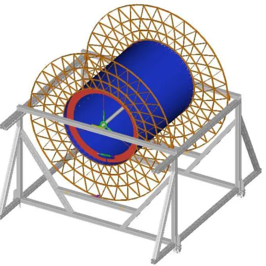
Figure 2. The TRT Barrel assembly, showing the Barrel Support System, in pink. The Barrel Support
System supports and locates the two ends of each module.
2. TRT Barrel and component specification
The mechanical design of the TRT Barrel must satisfy many requirements, including the ability to operate at high luminosity with high reliability, and, high mechanical rigidity while maintaining dimensional stability with a minimum amount of material, plus, a reasonable level of manufac-turability. Modularity has been used throughout the detector to simplify manufacturing and quality control, and to minimise at every stage the number of straws affected by any failure in the overall system. The TRT Barrel is divided into 96 modules of three types, arranged in three cylinders of 32 modules of each type, as shown in figure 2.
The modules are supported at each end by the Barrel Support System (BSS). Each module consists of a carbon-fiber composite cover or shell, an internal array of drift tubes, which are the detector elements, and an internal matrix of polypropylene fibers - the transition radiation material. The drift tubes (straws) were constructed from two layers of conductively-coated polyimide film. They form an approximately uniform array parallel to the beam axis, with an average spacing of about 6.6 mm between centers radially and tangentially. The layout of the drift tubes was designed to optimize the probability of the detection of transition radiation as well as to maximize the number of hits along a track. A more detailed description of the layout will be given when the straw positioning planes are discussed later.
2008 JINST 3 P02014
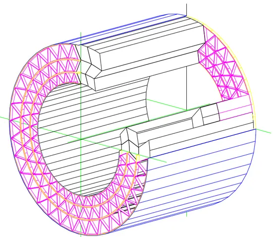
Figure 3. The three types of modules are mounted in the Barrel Support System. The orientation with
respect to the beam intersection area is shown to scale. The triangular sections on the space frame are radially symmetric.
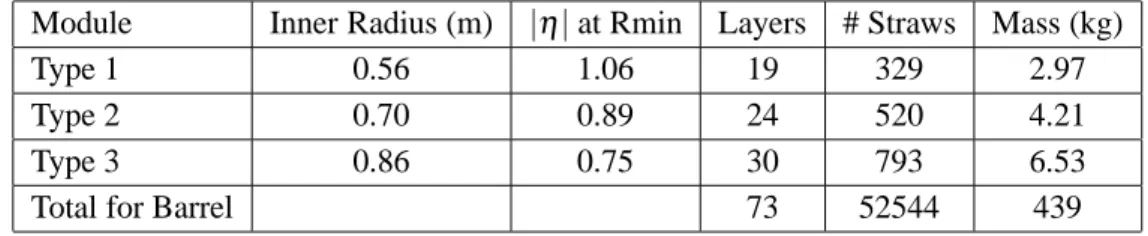
Table 1. TRT Barrel Module parameters.
Module Inner Radius (m) |η| at Rmin Layers # Straws Mass (kg)
Type 1 0.56 1.06 19 329 2.97
Type 2 0.70 0.89 24 520 4.21
Type 3 0.86 0.75 30 793 6.53
Total for Barrel 73 52544 439
A triplet of modules comprising a stack in azimuthal angle (“phi”) is shown in figure 3. The three sizes of Barrel modules are sequentially mounted in 32 “phi” sectors. Each module is a quadralateral prism with front and back faces in a plane perpendicular to the local radial ray, and sides that follow the close packing array shape of straws, approximating a 30◦ deviation with respect to a radial line. This design was choosen to minimize the amount of dead tracking area for high momentum particles. The resulting numbers of straws in each module are listed in table 1. The mass listed in the table are for modules only, with no electronics or external services connected. The total number of straws for all 32 sectors, and the total mass of the 96 modules is indicated in the bottom line of the table.
The straw diameter was chosen to be 4 mm as a reasonable compromise between speed of response, number of ionisation clusters, and mechanical and operational stability. The straw an-odes are 31µm-diameter gold-plated tungsten wires at ground potential and the straw cathodes are typically operated at a high voltage of 1530V, corresponding to a gas gain of 2.5 × 10⁴for the gas mixture chosen, which contains 70% Xe, 27% CO2, and 3% O2. To accomodate the high occu-pancy rate at the design luminosity, the sense wires are split in half by an insulating glass wire joint and instrumented with signal readout at both ends. The nine inner most layers are further divided into three sections with the middle section desensitized to further reduce the rate. The design and performance of the straw is described in detail in other documents [6, 21, 22], as is the evolution of the active gas mixture [14].
The dimensional specifications on the TRT were set by the requirements for the tracking preci-sion to be optimized for the drift tube straw intrinsic resolution of 130µm. Multiple measurements
2008 JINST 3 P02014
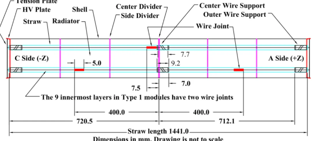
(a) Barrel module layout showing straw components and wire joint positions. Active sense wire regions can be calculated from the dimensions given. The upper straw shows a wire with single wire joint. The lower straw shows a wire with two wire joints.
(b) Isometric view of a module with end plates, radiator, straws and shell.
Figure 4. Layout of a Barrel module.
in each module linking through the three module layers required that the position (radially and tan-gentially) of each straw in a module be precise to±40µm, and the position of each module end to
±50µm. All mechanical components were constructed to satisfy these global specifications. Figure 4 illustrates the layout of a Barrel module. The Barrel components will be discussed in subsequent sections.
2008 JINST 3 P02014
2.1 Barrel Support SystemThe Barrel Support System (BSS) is the key structural component of the Inner detector assembly. It is comprised of two endframes connected together by an inner and outer cylinder. The BSS itself is supported on rails mounted to the inside of the ATLAS Liquid Argon Cryosat. It is shown in figure 2. The three layers of TRT barrel modules are supported at each end by the endframes of the BSS, and in addition the SCT barrel structure is supported by rails attached to the inside of the BSS inner cylinder.
The BSS is required to have minimal temperature related distortion, and maximal strength and stiffness since it determines the alignment of both the TRT barrel modules as well as the SCT. These constraints were satisfied, as well as restrictions on the mass and radiation length, by building the structure from carbon composites. The extensive performance requirements are given in CERN Technical Specification documents [42, 43].
The open strut system of the endframes was constructed from a large carbon fiber laminate disk, 21 mm thick, that was machined to produce the 2 meter diameter triangular strut array.The strut system permits access to the ends of each module, while at the same time giving high structural stability. The 3 mm diameter module mounting holes on the endframes ( two for each module end) were machined to within 50µm position tolerance from the hole’s specified position across the 2 m face. The two endframes are glued to a 2 mm thick continuous carbon fiber laminate cylinder at the inner radius forming the “spool” shown in figure 5. The BSS was manufactured in Russia [23]. Individual modules were inserted from the outer radius and were held at each end by two steel pins that pass through the precision drilled holes in the BSS and engaged a hole and a slot machined at two opposite corners of each module end assembly. After module insertion, two 3 mm thick carbon fiber laminate half cylinders were attached on the outside radius. The struts and cylinders were covered by copper foil to increase the conductivity of the carbon fiber to form a Faraday shield.
2.2 Shell specification and acceptance
The module shells were designed to minimize the thickness (and mass) of material while restricting the gravitational sag to less than 40µm in any module supported only at the ends. The
module-to-module shell separation was kept less than 1 mm, to avoid compromising the uniformity of the array of tracking points. The module shell also acts as a gas manifold for the flow of gas (CO2) that flushes the outside of the straw drift tubes and ensures that the ionization gas mixture, containing xenon, does not accumulate outside the straws through small leaks or diffusion. The flushing gas also ensures that we have a dry, high voltage insulating, gas outside the straws. This flushing gas enters at one end of the type-1 modules and passes serially through a “phi” stack of modules exiting at the opposite end of a type-3 module.
A module shell with the required 400µm wall thickness was produced in by a carbon com-posites manufacturer in California [24]. It was shown to satisfy the deflection requirements of a maximum of 40µm sagitta sag under full load in any orientation. The required flatness for the shell walls was 250µm. The design of the shell was based on 8 layers (90,+45,0,-45,-45,0,+45,90) of XN50A carbon fiber in a balanced, symmetric layup using RS12 resin. This fiber was chosen
2008 JINST 3 P02014
Figure 5. Barrel Support System without the outer cylinder halves which was attached after the modules
were installed.
for the very high thermal conductivity (200 W/(m · K)) since the module shells are cooled along
two edges, and must provide an approximately isothermal package.
At full LHC rates, the average ionization current generates significant heat in the gas. The heat generated is directly proportional to the straw counting rate and is estimated to be as high as 10− 20 mW per straw at LHC design luminosity. To satisfy the basic requirements on straw
operation stability and gas-gain uniformity, the temperature gradient along each straw should not exceed 10◦C. To meet this specification and to remove the heat, FluorinertTMliquid is used to cool the modules (and the front-end electronics). The liquid is passed through cooling pipes in the acute corners of each module in order to maintain the Barrel-module shells at an approximately constant temperature. A thin-walled Kapton° tube was glued in the two inside corners to hold the coolingR line in close contact to the wall. The thermal conductivity of the shell material was measured to be 57 W/(m · K). With the present shell material and the properties of the radiator, the internal
temperature rise at full luminosity is calculated to be less than 5◦C above the temperature of the cooling tubes. The calculation has been verified in a 0.5 m long prototype module [21].
2008 JINST 3 P02014
aluminum mandrels. A 50µm Kapton layer was bonded into the module as the first layer on thelayup. This was used for ensuring gas tightness and HV insulation between the shell and the straws which are at high volage. Upon receipt at our assembly sites the shells were checked for overall dimensions and thickness. The shells were cut to length (1444 mm) and penetration holes for the straw alignment planes were machined in the sides.
The modules were scanned with a touch probe device on a granite table to verify overall straightness and out-of-plane side panel deviations. All the shell edges near the corner at each side of the module were required to be within a specification of±200µm along the full length. The flatness requirement was that the module sides (which are much less stiff) were required to be extend no more than 500µm from nominal, which is the stay clear distance for each module. The average module shell weights were 570 g, 712 g, 892 g for types 1, 2, and 3 respectively.
2.3 Straw alignment plane (divider) specification and acceptance
The wire offset with respect to the center of each straw drift tube must not exceed 300µm for stable operation at the LHC. The maximum wire gravitational sag at wire tension of 70 grams-force is< 15µm, so the allowed offset is actually a specification on the straightness of each straw. In order to meet this centering requirement, the straw straightness must be maintained over the full length of the Barrel module to less than 300µm. It is the shell stiffness that provides, via the straw alignment planes, the necessary alignment of the straws, given that the gravitational sag of a fully loaded carbon-fiber shell has been measured to be< 40µm in any orientation.
Five alignment planes are positioned 25 cm apart along the module. Each plane has a straw-locating main sheet with two tabs on each edge (figure 6). The tabs pass through slots in the shell and holes in the tabs are held on an external alignment frame, and then glued to the shell. The aligment planes also function to maintain the shell wall profile under all loads, and so to strengthen them. To make assembly easier, each divider is sandwiched with two or three sheets of 100µm thick Ultem° film glued to one or two polystyrene foam spacers. Each sheet has an appropriaxteR pattern of holes; the main sheet in each divider has holes 4.3 mm in diameter and two alignment
tabs on each edge. The other sheet or sheets are stiffeners with larger holes and no tabs. Four of the five alignment planes have a main plane, foam spacer, and one stiffener sheet. The central plane has a stiffener, foam spacer, main sheet, foam spacer, and second stiffener, for symmetry.
The Ultem sheets and foam parts were wet machined by a precision instrument manufac-turer [25]. The perimeter features and the holes were wet machined in stacks of Ultem. Calibration testing had determined the expansion factor during wet machining for each type of sheet (∼ 1.004).
The machined sheets were washed and dried at an assembly site, and checked for dimensional cor-rectness by measuring the 4 corner positions with a Zeiss optical coordinate measuring machine with 5µm accuracy. The planes were then assembled at another assembly site.
Following assembly, each hole of each divider was inspected using a microscope to ensure that clearance was maintained and that the sheets were properly glued to the foam stiffeners.
2.4 Radiator specification and acceptance
The transition radiator material which completely surrounds the straws inside each module consists of polypropylene-polyethylene fiber mat about 3 mm thick [26]. This material had been chosen after
2008 JINST 3 P02014
Figure 6. A straw alignment plane (divider). This figure shows a divider for the Type 2 module. The external
tabs are for alignment only. They extend through small holes in the shell and are cut off after the divider is glued to the shell.
an extensive series of tests with prototype modules in CERN beam [2]. The fibers are typically 19µm in diameter and are formed from polyethylene clad polypropylene material. The fibers are formed into fabric plies with 3 mm thickness and a density of about 0.06 g/cm3. The absorption length for the lowest energy photons of interest (5 keV) is about 17 mm in the radiator material.
The fiber material was delivered as rolls 0.4 meter in width. The radiator fiber sheets were formed by stamping the pattern of straw holes into the fiber sheets. Three die sets that accurately cut the several hundred holes and the edges were produced. A production stamping company [27] punched the 50,000 fiber mats necessary for the TRT Barrel. A full-length module contains about 500 such pieces. The hole pattern is identical to that shown previously in figure 6 for the divider planes, except that the holes in the radiator material were 4.8 mm in diameter.
2008 JINST 3 P02014
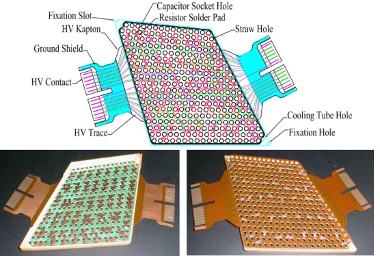
Figure 7. Upper plot is a transparent view of the HV plate showing HV circuits. Lower photos are front
and back view of a HV plate before bending the HV Kaptons. In the left hand photo one sees the thin plate inserted into the well of the thick plate and in the right hand photo one sees the Kapton HV feed on the reverse side of the thick plate. Connection between the HV feed and the thin plate is made via the capacitor socket.
of radiators arrived, they were accompanied by a test stamping sheet, so that obvious errors could be spotted quickly.
The boxes of radiator, each containing a known number, were weighed and sorted by density. Due to variations in the manufacture of the fiber, storage and compaction, and handling during stamping, the density varied considerably. However, aligned bundles of mats were sorted and shuffled to produce more uniform density. These bundles were produced at one of our assembly sites and distributed to all sites for insertion into the modules during assembly. Each of the bundles fit between the divider plane sections. The average weight of the radiator in each module was 1.12 kg, 1.65 kg, 2.59 kg for types 1, 2, and 3 respectively, with a variation of ∼ 2%
2.5 HV plates
The high voltage (HV) plates bring high voltages from outside the module into the straw cathodes. They also play an important role mechanically for the module structure and alignment. Figure 7 shows a drawing and photos of an assembled HV plate. The HV plate is made of three main components as described below.
2.5.1 HV feed
The HV feed is a Kapton flex circuit [29] that plugs into the fuse boxes and carries high voltage on a number of copper traces embedded in between layers of Kapton. Each trace goes to a surface-mounted 4.7 kΩ, 2.0mm × 1.3mm size filter resistor and is then connected to a pad that accepts a
2008 JINST 3 P02014
socket for a capacitor to return cathode signal current to analog ground. The HV feed is made inthree different layers. The center layer consists of 50µm Kapton sheet with 35µm rolled copper on each side. The two outer layers are 25µm coversheets of Kapton with 25µm acrylic bonding adhesive. The circuits were chemically etched on both sides of the center layer. Then, the part of each trace that will be in contact with the fuse boxes was selectively gold plated. No nickel or nickel flash were permitted before gold plating due to trace cracking problems that developed during bending of early versions.
2.5.2 Thick plate
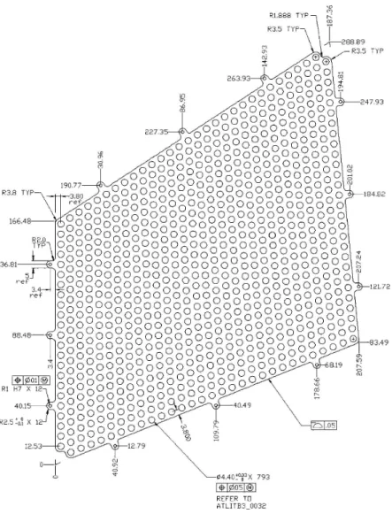
The thick plate is a tray shaped FR-4 [30]1structure precisely machined to mate between the tension plate and the shell and carries series of precision holes for mounting the module in the space frame, for holding the straws in their positions, and for the feed through of the module cooling tubes.
On the outer perimeter, the side facing toward the radiator must fit properly inside the module shell while the other end facing toward the space frame must be appropriately sized to not interfere with neighboring modules. The stated tolerance for outer perimeter dimensions is+0.0 mm and −0.10 mm per side.
The inner perimeter of the HV plate must allow clearance for the edge straws while simulta-neously allowing clearance for the cooling tube holes which penetrate the HV plate at the acute corners just outside the inner perimeter. The stated tolerance for this inner perimeter’s dimensions is±0.03 mm.The distance between the HV plate and the tension plate surfaces is 5 mm and must
be controlled to provide proper clearances for mechanical and electronic components in between. A major function of the HV plate is to locate each straw within the module. This is done by holes in the thick plate through which the straws pass. These holes, as well as the holes through the HV feeds and the thin plates (which are larger than the holes through the thick plate) must be aligned during assembly to allow subsequent insertion of the straws during module assembly.
The thick plate holes are located relative to the fixation pin holes/slots at the acute corners. These holes/slots fix the relationship between the modules and the attachment to the TRT Barrel Support System.
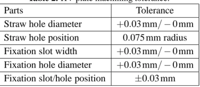
Table 2 lists the machining tolerance for the straw holes and the fixation holes/slots. The final precision on straw location requires that the deviation of the sense wire from the center of the straw shall not be more than 0.3 mm [1, 2]. An accumulation of tolerance limits the allowable circular
variation of straw hole-positions relative to the fixation/alignment holes. The tolerances listed in table 2, combined with the twister, sleeve, end plug, and straw tolerances result in an expected variance of wire center position of 91µm. This represents the part of the accumulated tolerance that can be allowed to HV plate assembly.
During production the thick plate hole positions were surveyed using a non-contact optical measuring machine [28] and compared to the theoretical values before they were assembled into HV plate.
1FR-4, an abbreviation for Flame Retardant 4, is a type of material used for making a printed circuit board,
2008 JINST 3 P02014
Table 2. HV plate machining tolerance.
Parts Tolerance
Straw hole diameter +0.03 mm/ − 0 mm
Straw hole position 0.075 mm radius
Fixation slot width +0.03 mm/ − 0 mm
Fixation hole diameter +0.03 mm/ − 0 mm
Fixation slot/hole position ±0.03 mm
2.5.3 Thin plate
The thin plate is a 0.2 mm thick single-sided FR-4 printed circuit [29] which carries pads that
con-nect each group of eight or seven straws to each other and to a capacitor-socket hole. This hole is aligned with a hole in the thick plate and the capacitor-socket hole in the HV feed. A capacitor socket passes through all three pieces of the HV plate and is top and bottom soldered to connect traces on the HV feed to pads on the thin plate.
2.5.4 Assembly of the HV plate
The three parts of the HV plate, the HV feed, the thick plate and the thin plate are first glued with Araldite° 2011 epoxy. Then, the resistors are soldered to the HV feed, and the capacitor socketsR are soldered to the thin plate and the Kapton circuit. The flaps of the HV feed are then bent 90◦ following the edge profile of the thick plate. This folding is done by heating and bending the Kapton on a 250◦C heating block. The heating block is machined to match the edge profile of the HV plate. After bending to 90◦the Kapton is clamped against the heating block to cool down. When the temperature reaches below 100◦C, the clamp is opened and AY103 epoxy is applied between Kapton and the thick plate. The assembly is then clamped again and the epoxy is allowed to cure overnight as it gradually cools to room temperature. Electrical continuity is checked between the Kapton feed and the thin plate sockets to ensure no breakage during the bending process.
2.5.5 HV stability
The electrical stability of the HV plate is characterized by its leakage current, the micro-discharge rate and the breakdown voltage under high voltage.
The leakage current measurement is repeated several times from trace to trace and from trace to shield during module production, and is required to be< 50 nA at 3000V in dry air.
The micro discharge rate was sampled for a finished HV plate and was determined to be
< 0.01 Hz at 5 pC threshold under 3000 V in dry Nitrogen.
Destructive breakdown voltage test was not carried out on finished HV plate, however, the HV plate operates at 3000 V in dry air without problem. Discharges sometimes occur due to contamination on the surface and can be eliminated by cleaning.
2.6 Tension plate
The tension plate is a 2-mm thick double-sided printed circuit board made of FR-4. It provides wire fixation mechanism using eyelets and taper pins, and, combined with the HV plate, forms a beam
2008 JINST 3 P02014
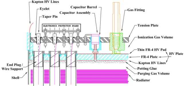
Figure 8. Tension plate and HV plate at module end.
structure that transfers wire tension to the carbon-fiber shell and the straws. In addition to taking the wire tension, the tension plate also serves as the interface between the module and the outside world. The empty space enclosed between the tension plate and the HV plate is a gas volume. This volume buffers the ionization gas from external pipelines into individual straws. The printed circuit traces on the inside of the tension plate brings signals from anode wires to an array of sockets on the tension plate. These sockets are where the external electronics is connected. The outer side of the printed circuit is a ground plane which provides signal return for the straws through HV blocking capacitors connected to the HV plate. The ground plane also serves as the analog ground for the external electronics [31]. Together with the shell, the tension plate is also part of a Faraday shield for the module. Figure 8 shows a cross section view of the tension plate region and its related components. The tension plate includes the following components:
2.6.1 Eyelets and taper pins
The eyelets are Stimpson stock item A1994 flat flange eyelets. The taper pins are custom machined part [33] to fit the eyelets, 3.43 mm long with a taper of 37 mm/m. Both eyelets and taper pins are made of brass and gold plated. A crimping mechanism is used to force the two brass pieces against the tungsten sense wire during stringing of the module. The back of the taper pin is machined with a blind hole. This is to reduce material and to facilitate handling and removal if needed. The diameter of the blind hole, 0.71 mm, is made to the tap size of a #1 screw so that a steel screw can be threaded into the taper pin and grab it for extraction.
2.6.2 Capacitors and capacitor barrels
The capacitor barrel provides a pocket between the tension plate and the HV plate that allows a capacitor to connect to the HV plate without disturbing the ionization gas volume. In the case of a capacitor failure, the capacitor can be replaced without having to open up the tension plate which would require cutting all the anode wires. The capacitor barrels, distributed across the tension plate
2008 JINST 3 P02014
surface, also serve as spacers to maintain distance between the two plates and transfer wire tensionfrom tension plate to the HV plate. The capacitor barrel [33] is made of Ultem 1000 with a double-sided pin glued at the end for electrical connection. The double-double-sided pin is gold plated brass and designed to fit the sockets on the HV plate on one end and the sockets on the capacitor on the other end. Because the capacitor barrel is part of the ionization gas enclosure, each assembled piece was tested with 1.4 bar dry air and submerged in water for 5 sec. to check for their gas tightness.
The capacitor is 875 pF NPO/COG type in an 4.6mm × 3.0mm size package. A reduced
length Mill-Max PGA socket is soldered on one end of the capacitor for connection to the double pin. A custom made bent pin is soldered on the other end for connection to the tension plate ground socket. Both sockets and tail pins are gold plated brass. To ensure reliability the capacitors have to withstand a burn-in at 2750V in dry air for 10 days. In this test, about 0.2% of the capacitors showed
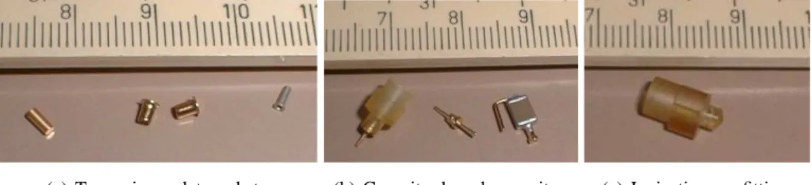
signs of breakdown and were rejected. The final capacitor assembly is coated with Hysol PC18M urethane coating to protect against contamination and humidity. The capacitors are not installed until the module is complete and ready for operation. After they are installed, a thin layer of AY 103 epoxy is applied over the opening of the capacitor barrel to add redundancy to the gas seal. This thin layer of epoxy can be removed with a small tip solder iron if it’s necessary to replace a capacitor. 2.6.3 Ionization gas fitting
Each tension plate is equipped with four ionization gas fittings [33] near the four corners. The gas fittings are machined from Ultem 1000. The gas fitting seats on the HV plate and shoulders against the tension plate. The fitting is hollow and threaded on the tension plate end for adapting to external gas lines. Three openings in the gas fitting near the HV plate end, 120◦angle apart, allow the gas to flow into the ionization gas volume uniformly. In normal operation, only one diagonal pair of fittings is used on a tension plate. The other 2 are sealed up as spares. On a module, the opposite pair of gas fittings are used on each side of the tension plate to force a more uniform gas flow through the straws.
2.6.4 Pre-assembly of tension plate
After the bare tension plate is made and cut into shape, the eyelets and sockets are soldered. When soldering the sockets, they are held by a mock up electronics board so that the socket arrays will fit for the electronics to plug in. The capacitor barrels and the gas fittings are then glued to the tension plate from the inner side. This glue is cured with a matching HV plate plugged into the capacitor barrel pins and the gas fittings seated to ensure that the glued components will fit their mating parts. After soldering and gluing, the components on the inner side of the tension plate are coated with a layer of sealing glue (AY 103) to ensure gas tightness. Figure 9 shows pictures of the various tension plate components.
2.7 Straw drift tube
The finished drift tube consists of a conducting ‘straw’ tube, sense wire supports at either end and the centre, plus the sense wire with an insulating joint, as described in the TDR [2], p. 653. Details of the design and the performance of the drift tube are described in a separate paper [22]. Mechanical assembly is described below.
2008 JINST 3 P02014
(a) Taper pin, eyelet, socket. (b) Capacitor barrel, capacitor. (c) Ionization gas fitting.Figure 9. Tension plate components.
Figure 10. Wire support drawings and photos. In the photo: Left a bare wire support (twister). Middle
-embedded in a cylindrical sleeve as a centre wire support. Right - -embedded in a flanged sleeve as an outer wire support.
2.7.1 Center and outer wire supports
The center and outer wire supports are designed to keep sense wires centred in the straw. The wire supports must not obstruct the flow of the ionisation gas going through the straw, and must allow installation or removal of the sense wire during module construction.
Wire supports consist of a twister [34] and a surrounding Ultem sleeve [35]. The twisters are cut from an Ultem rod with a machined helical groove [36]. The depth of the groove is 25µm greater than the radius of the rod, forming a 50µm diameter hole along the axis. The length of the twister is 7.7mm, a little over one pitch of a helix 6.88mm, so that the sense wire is constrained radially in all directions.
Figure 10 shows drawings and photographs of wire supports. The finished centre wire support is glued in a sleeve to provide an uniform surface for gluing to the inner straw wall. The outer wire support is embedded in a sleeve with a flange [33] to facilitate conductive gluing from the straw end to the HV pad on the HV plate.
2.7.2 Straw preparation and acceptance
Reinforced straws arrived at the U.S. preparation sites in batches from reinforcement sites at PNPI [37] and Dubna [38], sorted according to straightness; each straw was 1.65 m long. About 64,000 straws were processed.
2008 JINST 3 P02014
Figure 11. Glue dispenser in cut-away straw.
Glue
Wire
Support
Straw
Wall
Figure 12. Center wire support in cut-away straw showing cured glue.
Since the centre wire support is not at the precise centre of the straw (it is offset from|η| = 0),
each straw was first marked with a water-based latex paint at one end, to establish its orientation. Next, each straw was cut with scissors to a length of approximately 1.48 m, about 4 cm longer than the final length.
The next step was to glue in the centre wire support. This was done by batch in a jig. First, a drop of glue was placed by an glue dispenser at the centre of each straw. The dispenser was a glue reservoir at the end of a long stainless steel tube. Figure 11 shows the dispensing tip in a cut-away straw.
The glue-dispensing process required careful adjustment of tip distance from the straw, glue viscosity, air pressure, pressure pulse length, and speed of removal from the straw. Without correct adjustment, drops of glue can be left in the straw in the sensitive region. (This did occur in initial production, and led to the addition of a final quality assurance step: visual inspection of the inte-rior.) Centre wire supports were then pushed down each straw over the glue drop (figure 12). After a short time the straws were removed from the jig and allowed to cure.
The next stage was to check the straws for leaks. This was done with an automated version of the leak-test system described in the TDR [2], p. 660. An elastomer seal was inserted into each end of the straw and expanded against the inside with a supporting collar on the outside. At one end, a central tube allowed the straw to be pressurized with dry air to about 5 mbar. After a short time to allow the gas to come to equilibrium, the pressure was measured over an interval of two minutes. If the pressure fell at rate corresponding to a leak rate of greater than 1 mbar/bar overpressure/min, the test was registered as failed. It would then be re-tested. A straw can be re-tested up to three times
2008 JINST 3 P02014
before it’s rejected. Repeated tests were allowed because the sealing mechanism was imperfect:the interior winding of the straw created a spiral channel that could allow a leak. Overall, about 0.1% of straws failed this test, but that may have been due to seal failure, not straw leaks.
The design of the Barrel modules required that the straws were of a precise length: the end wire supports in each end of the straw had to contact the HV plate and not interfere with other components. The straw was cut to its final length, removing the part that had been in contact with the leak-test seal, in a cutting machine modelled after the one described in the TDR [2], p. 680. The production machine had rotating bypass shears made of tungsten carbide. The straw was mounted with a spacing rod inserted to position the centre wire support and the cylindrical internal ‘blade’ inserted into the ends. Clamps then held the straw in place while it was rotated so that the external blade cut the straw.
The length of every straw was assessed in a measurement jig using a digital dial gauge. The nominal straw length was 1441.00 ± 0.25 mm. Figure 13 shows the length assessments for about
65,200 straws, in terms of deviation from a nominal setting. The jig was set by indirect comparison with an Invar bar in combination with shims. One assembly site made and calibrated the Invar bars used by the other sites. A carbon-fiber rod with metal tips was then used to transfer the appropriate length from the bar to the measurement jig.
In addition to the length assessment, the position of the centre wire support was checked after the final cut.
The final step before packaging was interior inspection of the gluing side of the straw. This was done with an endoscope, about 2 mm in diameter, attached to a CCTV camera with the image displayed on a monitor. Straws with glue drops or other imperfections were rejected. Finally, the straws were packed in sealed polyethylene bags, with the batch bar code attached, and shipped to assembly sites.
2.8 Signal wire
The straw anode was a 31µm gold-plated tungsten wire. This wire was produced by Toshiba at the Yokohama, Japan factory. The base wire material was pure (99.95%) tungsten with a density of
19.22 g/cm3and was plated with pure gold. The thickness of deposited gold was 0.5µm minimum to 0.7µm. No nickel additives to the gold or nickel-flashing of the wire surface before gold plating were allowed.
Requirements on electrical stability for high rate operation, gas gain uniformity for Transition Radiation function, and radiation hardness for LHC environment imposed very stringent require-ments on the quality of the wire and its production processes. The wire ellipticity corresponding to wire diameter variation was required to be less than±2%. The finished, gold-plated wire was
required to have a tensile strength 700− 800 MPa.
The base wire had to be free of cracks, splits, or other defects. It was electrically polished to provide a smooth surface free from any pollutants and also carefully treated using light electrolytic cleaning to eliminate all traces of oxides and other possible pollutants immediately prior to gold plating.
The gold plating was required to be smooth, uniform and free of defects. Specifically, holes in the plating, poor adhesion, flaking, peeling, deep scratches, and blisters were not acceptable. The wire cleaning procedure following the gold plating process is critical. It ensured that the gold
2008 JINST 3 P02014
Figure 13. Straw length checks. The shift in the first 120 days is due to a mis-calibration of 0.15 mm.
surface is free from any chemical residue. No mechanical treatment of the wire surface was allowed after gold plating. This also implies special requirements for cleanliness and surface quality of all the parts of the set-up that are in contact with the gold plating surface during the gold plating process and the respooling process.
The wire was wound onto clean aluminium spools approximately: 95 mm ID×110 mm OD ×20 mm height. Each spool typically held 3 − 4 km of one continuous wire.
The wire was extensively inspected upon arrival using a scanning electron microscope (SEM) at North Carolina State University (Raleigh, NC). Typical images from these inspections are shown below in figure 14.
2.9 Wire joints
Due to the high occupancy of the straw tubes, especially at low R, it is necessary to split each sense wire into two electrically isolated wires, with each being read out from the corresponding end. To achieve this electical split, each sense wire consists of two wire sections joined by a length of glass tubing [39]. The pre-cut tubing, before any melting, is 6 mm long with an inside diameter
2008 JINST 3 P02014
Figure 14. Two images of accepted gold plated tungten sense wire under electron microscope.
of 0.127 mm, and an outside diameter of 0.254 mm. The glass, Kimble EN-1° type, was chosenR for its superior bond strength when fused to metal. The center 0.5 mm of each glass tube was
first fused in a methane-oxygen flame to form a ball to prevent the subsequently inserted sense wires from becoming electrically connected and to aid in the alignment of the tube in the wire joint tooling. Each center-fused tube was inspected for completeness of melting and straightness. To make wire joints, the sense wire is unspooled and cut near the center of the wire joint jig. The glass tube is held in the jig and the cut ends are fully inserted until stopped by the fused center and then fused by a pair of flames into the tube. The wire is then taken up by a spool so that the next cut is made 2 m from the previous wire joint. This produces a continuous batch of sense wire with sufficient extra length to allow for handling during module stringing. The finished length of each wire joint is in the range 5.0 − 5.5 mm. Each wire joint was visually inspected for completeness
of melting, and periodically wire joints were tested by attaching to a force gauge and pulling to destruction. Properly made joints are stronger than the sense wire itself, so the wire breaks at 200 g of pull rather than pulling out of the tube or the glass breaking. This is∼ 3 times the maximum
tension that the wires will have in the modules. For the straws at the smallest R, i.e. those in the first nine layers of each Type 1 module, the high occupancy requires that approximately the center third of the wire not being read out. For this case sense wires were produced with two joints per wire, spaced apart to create an 80 cm dead segment as shown in figure 4(a). Figure 15 shows a completed wire joint.
2.10 Preparation and acceptance of components
An important aspect of the manufacturing process was the shift from prototype methods to series production with consistent quality assurance procedures. To achieve a degree of uniformity, most or all of several kinds of components were prepared at a single facility at Hampton University and shipped to assembly sites at Duke University and Indiana University. These parts included straws, wire supports,dividers, shells, HV plates, tension plates, etc. A total of about 500,000 parts were processed, a database being used to track parts and batches, and to guide the preparation process — instructions for each procedure were presented to the technician on a screen and a response was required on the completion of each step. Bar codes on items or batches were recorded so that there was assurance that processing and assembly procedures were followed.
2008 JINST 3 P02014
Figure 15. From the bottom up: a pre-cut glass tube, a center-fused glass tube, and, a glass wire joint fused
to two sense wires. The fused center of the glass tube prevents the two wires from touching each other. White mark on top is a ruler in mm scale.
2.10.1 Common preparation processes
There were common features to the preparation of many parts particularly in cleaning and gluing. Cleaning of small parts made of metal or Ultem (twisters, wire support sleeves, capacitor bar-rels, taper pins, etc.) was done via ultrasonic cleaning using a 2% solution of Micro-90 detergent in distilled water. Following this cleaning, the parts were rinsed in distilled water until the conduc-tivity of rinse water was not distinguishable from that of distilled water. The parts were then dried in an oven at 110-120◦C for 45 minutes, spread out on a tray in a single layer.
Assembly of composite parts (e.g., wire supports, dividers) was done with an appropriate epoxy. To speed up production, epoxy was set by baking the parts in suitable jigs for 1.5 hours at 60 to 65◦C.
Specifications and quality control tests for small parts varied. For wire supports, samples from each batch were tested for adhesion of the twister to the sleeve by applying a longitudinal force; the glue joint had to support a load of more than 9 kg.
The brass taper pins were finish plated with 1.3µm of 99.7% gold (130 Knoop hardness) over 2.5µm of nickel, and over 2.5µm of copper base plating. Quality control was by visual inspection of completeness of coverage. A similar specification was used for the tension plate eyelets.
3. Electronics and services
3.1 High voltage
High voltage is supplied to the TRT Barrel from power supplies in the electronics room through
∼ 100m of cables divided into 3 sections. The last section starts from the outer edge of the Barrel
and distributes HV to the modules through sets of fuse boxes. Each fuse box is a two-half FR-4 shell enclosure containing filter circuits, fuses and spring contacts for direct connection to the HV feed in front of the modules.
2008 JINST 3 P02014
Figure 16. HV cable routing and fuse box connections to the modules. Six fuse boxes for 1 stack of 3
modules are bundled into 1 HV connector at the outer edge (bottom) of the Barrel.
A Barrel module has two HV feeds at each end to receive high voltage, however, fuse boxes and HV are only supplied to one end of the module. The two HV feeds on the other end are used as spare and protected by empty FR-4 dummy fuse boxes. Real and dummy fuse boxes alternate between neighboring modules and split HV lines equaly between the two ends of the Barrel. The wiring and fuse boxes are designed such that if one end of a module has a defect and is unable to receive HV, the other end can be used by swapping cables with its neighbors. Figure 16 shows fuse box connections on the modules.
3.1.1 Fuse box design and HV granularity
Inside each half of a fuse box is a 0.15mm thick double-sided printed circuit board glued on to the FR-4 casing and holding all the components as shown in figure 17. The HV mini coax cable entering the fuse box first goes through a filter circuit consisting of 1kΩresistors on HV and return lines bridged by a 875 pF HV capacitor. The filtered return line then goes to a spring contact that will connect to the analog ground of the electronics. The HV line goes through fuses to the spring contacts that will connect to the module HV traces.
2008 JINST 3 P02014
power supply trips. When there is a broken sense wire and the fuse has to be disabled, a specialHV pulse is injected from the power supply side to blow the fuse.
The nominal TRT operating voltage is 1530V. The fuse boxes are required to hold 2 kV with a leakage current less than 50 nA per HV line. After soldering and cleaning, they are baked and coated with urathane conformal coating to reduce surface leakage current.
The HV granularity is a trade off between cost, performance and tolerance in losses:
1. In order for the straw gas gain to be uniform across the Barrel, the voltage drop over the fuses and filter resistors due to current draw in the straws can not be more than 7 V at the design luminosity. This sets an upper limit on how many straws can be fed from a fuse or a HV line. 2. In case of a HV failure inside the detector, e.g. a broken sense wire, we want to minimize the number of straws that have to be shutdown by a fuse. This number is determined to be 8, and is implemented on the HV plate which groups 8 straws to share one trace on the HV Kapton. 3. To minimize the cost, a HV power supply should drive as many straws as possible up to a limit either set by the number of straws or the current draw. Based on the power supply specification, the nominal load assignment to a power supply is chosen not to exceed 1.5 mA, and, the maximum number of straws is chosen to be less than 100.
With these criteria, GEANT simulation was used to estimate current draw on each fuse at projected LHC luminosity. The fuses are then grouped to share HV power lines within the current limit. To simplify fuse box production and installation, symmetry is taken into account, and, the fuses are grouped such that one fuse box layout can be used on all 4 possible HV Kapton positions in a module. The results are 6 lines for a type 1 module, 6 lines for a type 2 module, and 10 lines for a type 3 module. The number of straws each line drives ranges from 48 in a type 1 module to 96 in a type 2 module. Type 3 module was assigned a uniform 80 straws per line for simplicity, despite its lower current draw [41]. The HV circuit and a picture of the layout with fuse grouping is shown in figure 17.
3.2 Electronics
The basic front end electronics [31] for the TRT Barrel is schematically the same as the electronics for the TRT End Cap - an ASDBLR (Amplifier, Shaper, Descriminator, Base Line Restorer) analog signal processing chip followed by a DTMROC (Drift Time Measurement Read Out Chip) time measuring.
The 8 channel ASDBLR ASIC in DMILL technology [32] performs the amplification, shaping and base line restoration. It includes two discriminators, one at low threshold for minimum ionizing signal detection and one at high threshold for transition radiation detection;
The 16 channel DTMROC in commercial 0.25m CMOS technology performs the drift time measurement (3 ns binning). It includes a digital pipeline for holding the data during the level 1 trigger latency, a derandomising buffer and a 40 Mbits/s serial interface using LVDS (Low Voltage Differential Signaling) for the readout. It also includes the necessary interface to the timing, trigger and control as well as DACs to set the ASDBLRs thresholds and test pulse circuitry for mimicking analog inputs to the ASDBLRs. These ASICs are housed on front-end boards attached to the detector. Details of this electronics can be found in the TRT electronics publication [31].
2008 JINST 3 P02014
565-1087
ȝA/line
999-1253
ȝA/line
498-735
ȝA/line
1
2
3
4
5
1
2
3
1
2
3
1
2
Fuses
HV
Cable
Spring
Contact
(a) The fuse box layout for module types 1, 2, and 3 from left to right with fuse grouping indicated in white and current draw ranges in black.
(b) Schematics showing HV circuit.
2008 JINST 3 P02014
3.2.1 Protection boardsPhysical connections of the anode wires and the tension plate ground reference to the front end electronics is made via a small 22 pin "protection board". Each protection board connects 16 anodes and 6 signal returns using 0.5 mm diameter gold plated brass pins in a common physical pattern repeated across the faces of the modules. The corner pins for each protection board have PEEK2standoffs to ensure a common mating height for all the protection boards on a module. The outer surface of each protection board has a miniature 50 pin connector for connection to the front end electronics boards. The 50 pin connector has enough contacts to allow each anode signal to be accompanied by a "dummy" signal from the protection board up to the front end and the ASDBLR inputs and for each pair of anode and dummy to be separated by a signal return trace. The remaining surface area on both sides of the protection board is used to mount a limiting resistor (24 Ohms) and a clamp diode for each anode signal to provide additional protection for the ASDBLR inputs against electrical discharge.
The other function of the protection boards is to allow a mechanical degree of freedom for at-taching the front end boards to the modules - even the smallest of the front end boards has ten pro-tection boards, 220 brass pins that would be difficult to insert simultaneously and the largest front end board has 594 pins. The 50 pin connectors themselves provide some 300 microns of mechanical compliance which adds to the degrees of freedom for each individual protection board and yields a mechanical system that allows a surprisingly easy and reliable manual insertion of up to 1350 individual connections between the largest front end board and its ensemble of protecion boards. 3.2.2 Front end boards
The front end electronics for the TRT Barrel has physical and thermal constraints that are tighter than those for the Endcaps, thus the Barrel final front end board designs turned out to be signifi-cantly more challenging. Instead of a two board design for the Endcaps which allows some physical separation of the ASDBLR analog and DTMROC digital circuitry, both chips were combined on a single physical triangular substrate. More details can be found in [31].
The readout is segmented in 32 stacks in “phi” to ease the level 2 trigger task of data retrieval. The readout uses 40 Mbits/s electrical LVDS links to patch panel boards (PP2) located up to 13 meters away just after the first muon chambers. Further details about the back end electrlnics and the off-detector DAQ can be found in [31].
3.3 Cooling plates
The electronics as well as the modules themselves need to have heat removed from the detector area. This is accomplished by circulating C6F14 (Fluorinert) from a central cooling plant to four distribution racks located near the detector and through the modules in the detector. For the design and tests of the cooling system it has been assumed, with enough of safety margin, that FE electron-ics generates 100 mW/channel. This heat is removed by conduction from surface of the DTMROC chip directly to an aluminum cooling plate attached to each of the electronic roof boards. The Fluorinert is carried by a cooling manifold from the outside radius of the BSS to the modules. In
2PEEK, Polyetheretherketone, is a thermoplastic with extraordinary mechanical properties,
2008 JINST 3 P02014
Figure 18. Exploded View of Cooling plate.
order to cool the modules themselves, which can produce up to 6 W/module at highest luminosity, the Fluorinert exits each cooling plate and passes along the length of the module to the opposite end before being carried away by a manifold to the outer radius of the BSS and ultimately back to the pumping station. There is a module cooling tube inside the shell in each of the acute corners of every module. This module cooling tube is made of 3mm PEEK and is connected to the electronic cooling plate at one end, and exits via the manifold at the other end. The nominal entrance temper-ature of the fluid is 15◦C, and the fluid flow is set to have a maximum temperature increase of less than 8◦C at the return.The cooling plate itself is shown in figure 18.
The cooling plate is made from two triangles of aluminum with aluminum input and output connections. All components are bonded with epoxy - Epibond 420. The top plate is machined to produce a path for the cooling fluid directed over the tops of the electronic chips. For increased protection against de-laminating, the two plates are riveted in numerous places as well as being glued. All plates were tested for tightness at 10 bar. The nominal operating pressure is about 3 bar. The specifications for leak tightness was< 100 l/year for the entire manifold and plumbing
system. The leak rate in any cooling plate was too low to measure, it was expected that the major loss would be in the interconnects of the manifold and plumbing connections. The cooling plates and manifolds have a total volume of about 3 liters while the plumbing ditribution lines from the racks in the cavern is more than 200 l. The coolant flows are 0.6 l/min for a type 3 module and 0.5 l/min for type 1 and type 2 modules.
3.4 Active gas, flushing gas and manifolds 3.4.1 Active gas
The active gas for the straw drift tubes is Xe(70%), CO2(27%), O2(3%). This gas is supplied through two ports at one end of each module, and exits from two ports on the other end of each
2008 JINST 3 P02014
Figure 19. The cooling and active gas manifold for an 1/16 “phi” section. Active gas (five leftmost fittings)
and cooling fluid (the next four fittings on the right) are supplied from the large radius fittings and distributed to the three layers of modules.
module. The gas volume within the module itself is the volume between the tension plate and the HV plate and the straws themselves. For the three module types the nominal flow rate is 110 cc/min for type 1, 170 cc/min for type 2, and 240 cc/min for type 3, which results in about one volume change per hour. The exit gas is recovered, cleaned and recirculated.
3.4.2 Barrel manifold
At each end of the Barrel there is a PEEK based manifold that carries active gas to each module. For the innermost modules (type 1) one manifold line feeds two modules in parallel. The active gas lines are part of the Barrel manifold shown in figure 19. The active gas and cooling manifolds are physically grouped into a radial network that links the supply line at the outer BSS radius to the individual modules.
3.4.3 Flushing gas
In the TRT Barrel the individual drift straws are separated by several millimeters. In between the straws there is the TR radiator. It is very important that Xe does not fill this region, otherwise the transition radiation photons would deposit their energy outside the straws. In order to sweep away any small amount of active gas that might have leaked or diffused from the straw wall, the radiator region is flushed with CO2. The shell of the module has access holes that act as the manifold for this gas volume. The CO2gas flows at a rate of about 500 cc/min per stack of 3 modules. The gas enters at the inner radius of the innermost module, flows the length of this module and exits via a gasket coupling to the inner side of the middle module. Again it flows the length of the middle module and exits into the inner side of the outer most module, passing along its length and exiting at the outer radii. This is done for each of the 32 module stacks in “phi”. The entrance end for