Abstract— In this paper, we present equivalent circuit for
immersed capacitive micromachined ultrasonic transducers (cMUT), based on an accurate parametric model. We also present an accurate approximation for the radiation impedance cMUT. We develop a design approach for immersed cMUTs using the equivalent circuit. We demonstrate that the equivalent circuit predicts the performance of a cMUT array element composed of many cells in parallel. We investigate the applicability of the equivalent circuit in designing cMUT array elements.
I. INTRODUCTION
uring the era, when capacitive micromachined ultrasonic transducers (cMUT) were first reported [1], most of the effort was spent on the modeling [2] and the fabrication [3]. Modeling still remains as an important issue in order to have a better understanding and the optimization of the operation of cMUT [4].
When operated in air, there is a good agreement between the Mason’s equivalent circuit and the experimental results [3]. However, when immersed in fluid medium, modelling approaches fail in the explanation of the radiation impedance that cMUT experiences. In this work, using the results obtained in [5], the designs of various cMUT array elements are presented. Practical considerations such as parasitic capacitances are included in all design examples.
In [6], it is shown that the model depicted in Fig. 1, which is derived from Mason’s impedance equation [7], represents the mechanical impedance of cMUT exactly up to the third parallel resonance when operated in vacuum. Although, the mechanical impedance of the membrane deviates from Mason’s expression as it gets thicker, this affect is accurately taken into account in [6]. The model has one electrical port and two sets of symmetric acoustics ports corresponding to the two faces of the membrane. In vacuum, both surfaces are terminated by F=0. At the electrical side, C0 and –C0 represent
the shunt input capacitance and the capacitance arising from the membrane motion. n is the turns ratio calculated using the procedure described in [8]. In this circuit,
Cmk and Lmk represent the compliance and the mass of the
membrane. Their values can be calculates as [6],
2 2 ( / ( )), 1, 2, 3, 4 ( ) mk k t mk k t C C a c l k L L a l πρ π ρ = = = (1) where 2 0 0 2 (1 / ) 12 (1 ) t T Y l c Y ρ σ + = − (2)
Here a and lt are the radius and the thickness of the membrane,
respectively. ρ is the density, σ is the Poisson’s ratio, Y0 is the
Young’s modulus and T is the residual stress of the membrane material.
The values of Ck and Lk can be obtained from the following
polynomial constructed in terms of lt/a [6],
3 2 1 3 2 1 0 for 0.2, 1, 2,3, 4 k t t t k t C l l l q q q q L a a a l k a = + + + ≤ = (3)
where the coefficients, qi, of the polynomials for Ck and Lk are
given in Table I.
Radiation Impedance and Equivalent Circuit for
Immersed CMUT Array Element
Muhammed N. Senlik, Abdullah Atalar, Hayrettin Koymen, and Selim Olcum Electrical and Electronics Engineering Department, Bilkent University, Ankara, TURKEY
D
Fig. 1. Lumped element model of mechanical dynamics of cMUT membrane.1951
©
TABLE I
MODEL PARAMETERS OF cMUT
cMUTs are operated under bias in order to have a better electromechanical conversion. Under these circumstances, only C1 and L2 are affected. These affects can be accounted for
as [6], 2 2 2 4 0 1 1 2 4 0 2 2 1 1 0.025 (1- 3.54 7.0 ) 1 1 1 0.025 1 t unbiased t unbiased d C l C d L l L γ γ γ γ ≈ + + ≈ + (4)
Here d0 denotes the effective gap height of cMUT and γ is the
ratio of the operating voltage to the collapse voltage, Vcol.
II. MODELLINGOF CMUTINWATER
cMUTs are immersed in a medium for operation. In this work, we assumed that the immersion fluid is water. However, the modeling is valid for other fluid media. In this case, the back surface will still be terminated by F=0, but the front surface is in contact with water. When the acoustic ports are terminated accordingly, the equivalent circuit in Fig. 1 reduces to the one in Fig. 2 [5]. This equivalent circuit models the membrane when loaded with water, up to the vicinity of first
parallel resonance frequency.
The series path in the circuit denotes the piston motion of the membrane. In this sense, the membrane sees the radiation impedance of an equal sized circular piston, which is
2
( ) ( ( ) ( ))
W w w
Z ω π ρ= a c R ka + jX ka (5)
where ρw and cw is the density of the water and the speed of
sound in water. However, the distribution of the particle velocity on the membrane surface has a non-uniform profile and brings in an inductive loading denoted by LmWL. The
inductive loading represents the mass of the water moved by the membrane apart from the piston motion. This mass is approximately equal to the mass of water in one half of the hemispherical volume above the membrane [5],
3 0.25 (4 / 3)
mWL W
L = ρ πa (6)
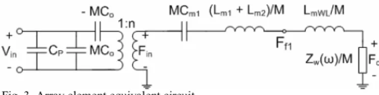
In order to construct an array element, many identical cMUTs are connected in parallel. We obtain in the equivalent circuit in Fig. 3 [5], where M denotes the number of cMUT cells in an array element.
Since the circuits are connected in parallel, the capacitance values are multiplied with M, whereas the inductor and the impedance values are divided by M. CP accounts for the total
parasitic capacitance due to the interconnections between cMUTs and the cable connecting the electronics. Here, we assume that the mutual loading between the cMUT cells is negligible and the moved water represented by LmWL remains
local to each cell.
If the fill factor, fF is defined as the ratio of the total cMUT
membrane area to the element area, then the effective radius of array element will be,
/ F
r a M f≈ (7)
The radiation impedance per cMUT becomes, 2
( ) ( ( ) ( ))
W w w
Z ω π ρ= a c R kr + jX kr (8) If we write down the resonance equation for the circuit in Fig. 3 at the series resonance frequency, ωs we obtain,
( ) 1/( ) 0
L s s sT
X ω − ωC = (9)
where XL(ωs) and 1/(ωsCsT) are the total inductive and the
capacitive loads in the series path at the series resonance frequency.
If we rearrange the resonance equation (9) to write a polynomial in powers of a/lt, we obtain [5],
q1 q2 q3 q4 C1 -0.007167 0.03620 -0.0005467 0.005208 L1 -6.523 -3.868 0.02025 1.202 C2 -0.05307 0.01826 -0.0002122 0.0003314 L2 10.46 0.2339 0.06243 0.5983 C3 -0.004264 0.003400 -0.0001039 0.0006432 L3 -5.921 10.49 0.02132 0.3082 C4 -0.05627 0.0330 -0.0001758 0.0008004 L4 4.733 -0.04884 -0.01920 0.1546
Fig. 2.Equivalent circuit of a cMUT membrane immersed in water; Zw(ω)
is the radiation impedance of piston, Zw(ω) = πa2ρwcw(R(ka) + jX(ka)).
Fig. 3. Array element equivalent circuit
( )
(
)
( )
3 2 2 2 1 2 2 0 ( ) 1 3 1 0 s w t s t s X k r a a a a L L a l k r r r l r e k r ρ ρ + + + − = (10) where 1 2 / w o s t c C e f c l = (11)Here fs denote the spring softening factor. C1 and L1 + L2 are
0.0052 and 1.8, respectively. The typical value for fs, when γ is
0.9, is 0.77.
To design a cMUT array element at a specific resonance frequency, one can solve (10) to find a/lt, from which lt can be
calculated for the desired a value.
In order to check the accuracy of the model, we compared the results obtained from the equivalent circuit with the experimental work given in [9]. The array element consists of 16 cMUTs (M=16) having silicon nitride membranes, we used the material properties given in [9]. For a single cMUT, a and
lt are 16µm and 1.8µm, respectively. If we choose d0 as 0.2µm
and fF as 0.68, Vcol and n become 179V and 48.8µNt/V per
cell, respectively. The operating voltage is assumed to be 90% of Vcol. Although parasitic capacitance due to cMUT
interconnections is low, around 2pF, the cable parasitic is one order of magnitude higher [9]. We assumed total Cp to be
30pF. The transfer function Re{(Fc/Vin)} for transmission and
open circuit transfer function |Vin/Fc| for reception are
depicted in Fig. 4.
The center frequency is approximately at 16 MHz. The device has a two-way insertion loss of -40dB with a 6dB bandwidth of 13 MHz. It can be seen from Fig. 4 that there is a very good agreement between the equivalent circuit predictions and the experimental data [9].
III. DESIGNEXAMPLES
It is possible to construct a cMUT array element, where the aperture size is chosen such that kr is larger than 2 in the bandwidth. Hence the radiation resistance remains constant, whereas the radiation reactance has a low value, which in turn results in a good transmission performance. Consider an 8x8 array (M=64) made of silicon nitride. The material properties,
Yo, ρ and σ for silicon nitride are assumed to be 320GPa,
3270kg/m3 and 0.263, respectively. We choose f
F to be 0.5,
which is a reasonable value for an array having such a high volume of cells. Let the effective radius of the array be 300µm, and hence a is 26.5µm. If the resonance frequency is chosen to be 1MHz, we obtain a/lt = 26 from (10), hence lt
must be 1µm. d0 is chosen to be 0.15µm. In this case, Vcol and n become 25.6V and 34.5µNt/V. Cp is assumed to be 30pF.
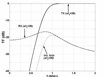
The transfer functions both for transmission and reception, and the insertion loss are given in Fig. 5.
Fig. 5. Transmission and reception transfer functions for a large aperture array, (a/lt=26)
The array element has an excellent transmit performance around 1 MHz as expected. If we consider the reception, we see that the bandwidth deteriorates due to the parallel capacitances, C0 and Cp. Array element has a two-way
insertion loss of -19dB with a 6dB bandwidth of 0.71MHz. In order to have a high fF, let’s design a phased-array
element containing single cMUT. The resonance frequency is chosen to be 10 MHz, making λ/2 to be 75µm. If we choose the radius a as 35µm, then lt becomes 4.5µm giving a/lt equal
to 7.8 (Eq. 10) and fF 0.68. d0 and Cp is again chosen as
0.15µm and 30pF. Vcol and n are 135V and 310µNt/V,
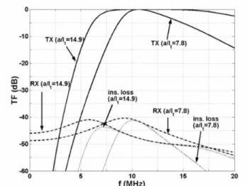
respectively. The transmission and reception transfer functions are shown in Fig. 6. The device has a two-way insertion loss of -41dB around 10MHz with a 6dB bandwidth of 4.3MHz.
If we increase the number of elements in the array to 9, while keeping the aperture size and fF constant, a becomes
14.1µm and (10) advises that a/lt is 14.9 (lt =0.95µm) in order
that cells resonate again at 10 MHz. The transfer functions for this design are also depicted in Fig. 6. Compared to the single Fig. 4. Transmission and reception transfer functions.
element case, the two-way 6dB insertion loss bandwidth is wider at 7.4MHz but with a higher loss level of –44dB.
IV. CONCLUSION
In this work, we described a method to estimate the radiation impedance of a cMUT, which is a series combination of an equal sized piston and an extra mass of water. We present an equivalent circuit for immersed cMUT. We showed that the circuit predicts the performance of realized array elements very accurately. We demonstrated the use of this circuit in the design of cMUT arrays elements. We showed that the dimensions of cMUT cells can be accurately determined for a specified operational condition.
The equivalent circuit is useful to accurately estimate the performance of small aperture array elements as well. A single cell per array element design is compared with multi cell element of same size and same resonance frequency. We showed that increasing the number of elements increases the bandwidth at the expense of increased insertion loss.
V. ACKNOWLEDGEMENTS
This work is supported in part by Turkish Scientific and Research Council (TUBITAK) under project grant 105E023.
REFERENCES
[1] M. I. Haller, and B. T. Khuri-Yakub, “A Surface Micromachined Electrostatic Ultrasonic Air Transducer,” IEEE Trans. Ultrason., Ferroelect., Freq. Contr., vol. 43, pp. 1-6, 1996.
[2] A. Bozkurt, I. Ladabaum, A. Atalar, and B. T. Khuri-Yakub, “Theory And Analysis Of Electrode Size Optimization For Capacitive Microfabricated Ultrasonic Transducers,” IEEE Trans. Ultrason., Ferroelect., Freq. Contr., vol. 46, pp. 1364-1374, 1999.
[3] X. Jin, I. Ladabaum, and B. T. Khuri-Yakub, “The Microfabrication Of Capacitive Ultrasonic Transducers,” IEEE J. Microelectromech. Syst., vol. 7, no. 3, pp. 295-302, 1998.
[4] S. Olcum, M. N. Senlik, and A. Atalar, “Optimization Of The Gain-Bandwidth Product Of Capacitive Micromachined Ultrasonic Transducers,” IEEE Trans. Ultrason., Ferroelect., Freq. Contr., vol. 52, pp. 2211-2219, 2005.
[5] H. Koymen, M. N. Senlik, A. Atalar, and S. Olcum, “Parametric Linear Modeling Of cMUT In Water,” unpublished.
[6] H. Koymen, M. N. Senlik, A. Atalar, and S. Olcum, “Parametric Linear Modeling Of cMUT In Vacuum,” IEEE Trans. Ultrason., Ferroelect., Freq. Contr., submitted for publication.
[7] W. P. Mason, Electromechanical Transducers and Wave Filters, 2nd ed.
New York: D. Van Nostrand Company, Inc., 1948
[8] S. Olcum, A. Atalar, H. Koymen, and S. Olcum, “Calculation Of Transformer Ratio In Mason’s Equivalent Circuit For CMUTs,” IEEE Ultrasonics Symposium 2006 , to be published.
[9] J. Knight, J. McLean, and F. L. Degertekin, “Low Temperature Fabrication Of Immersion Capacitive Micromachined Ultrasonic Transducers On Silicon And Dielectric Substrates,” IEEE Trans. Ultrason., Ferroelect., Freq. Contr., vol. 51, pp. 1324-1333, 2004. Fig. 6. Transmission and reception transfer function for a/lt equals to 7.8
and 14.9.