RESERVATION FRAME SLOTTED ALOHA
FOR MULTI-CLASS IOT NETWORKS
a thesis submitted to
the graduate school of engineering and science
of bilkent university
in partial fulfillment of the requirements for
the degree of
master of science
in
electrical and electronics engineering
By
Mahzeb Fiaz
January 2019
Reservation Frame Slotted ALOHA for Multi-Class IoT Networks By Mahzeb Fiaz
January 2019
We certify that we have read this thesis and that in our opinion it is fully adequate, in scope and in quality, as a thesis for the degree of Master of Science.
Nail Akar(Advisor)
Ezhan Kara¸san
Mehmet Akif Yazici
Approved for the Graduate School of Engineering and Science:
Ezhan Kara¸san
ABSTRACT
RESERVATION FRAME SLOTTED ALOHA FOR
MULTI-CLASS IOT NETWORKS
Mahzeb Fiaz
M.S. in Electrical and Electronics Engineering Advisor: Nail Akar
January 2019
The Internet of Things (IoT) is a promising technology capable of revolutionizing our work and daily lives. ALOHA based medium access schemes are widely used in IoT applications due to their low complexity despite lower throughput figures. In this study, we aim to improve the performance of Frame Slotted Aloha (FSA) for a single hop IoT network without increasing the overall complexity. Duty cy-cling is a key concept for managing energy consumption of wireless networks with battery powered nodes having maximum duty cycle constraints. The goal of this study is to improve the performance of frame slotted Aloha by exploiting duty cycle patterns in these networks and using reservations in advance. We discuss the system model for a single class IoT network and study via simulations the performance of Reservation Frame Slotted Aloha (RFSA) as compared to FSA, as well as the performance implications of different system parameters related to traffic patterns. With the insight gained from this preliminary study, we next study a multi-class IoT network with nodes belonging to different classes with different duty cycle constraints. Adopting RFSA for such a network requires dif-ferent schemes for allocating channel resources for each class. We propose several static and dynamic channel allocation schemes based on our traffic model and study their performance as compared to FSA. Static partitioning has better per-formance for low traffic loads but dynamic partitioning offers better throughput at higher traffic loads. Selection of an appropriate channel allocation scheme can vary according to the load as well as several system parameters of the network.
Keywords: ALOHA, Internet of Things,Frame Slotted ALOHA, R-ALOHA,
¨
OZET
REZERVASYON TABANLI C
¸ ERC
¸ EVE-D˙IL˙IML˙I
ALOHANIN C
¸ OK-SINIFLI IOT A ˘
GLAR ˙IC
¸ ˙IN
KULLANILMASI
Mahzeb Fiaz
Elektrik ve Elektronik M¨uhendisli˘gi, Y¨uksek Lisans Tez Danı¸smanı: Nail Akar
Ocak 2019
Nesnelerin ˙Interneti (IoT), i¸simiz ve g¨unl¨uk hayatımızda ¨onemli de˘gi¸sikliklere
yol a¸cma potansiyeli olan bir teknolojidir. ALOHA tabanlı ortam
eri¸sim y¨ontemleri, g¨oreceli d¨u¸s¨uk verime sahip olmalarına ra˘gmen, d¨u¸s¨uk karma¸sıklıklarından dolayı, IoT uygulamalarında yaygın olarak kullanılmaktadır. Bu ¸calı¸smada, tek sekmeli bir IoT a˘gı i¸cin C¸ er¸ceve-Dilimli ALOHA’nın (FSA) ba¸sarımını arttırmak hedeflenmektedir. G¨orev zaman dilimleme, kablosuz a˘gların enerji t¨uketimini y¨onetmek i¸cin ¨onemli bir kavram olarak ortaya ¸cıkmaktadır ve lisanssız spektrumda ¸calı¸san a˘gları kullanan d¨u˘g¨umlerde bir maksimum g¨orev d¨ong¨us¨u kısıtlaması mevcuttur. Bu ¸calı¸smanın amacı, bu a˘glarda g¨orev d¨ong¨us¨u paternlerini kullanmak suretiyle ¨onceden rezervasyon yapılarak FSAın ba¸sarımını arttırmaktır. Oncelikle, tek-sınıflı bir IoT a˘¨ gı i¸cin sistem modeli ¨onerildi ve sim¨ulasyon y¨ontemi kullanılarak, ¨onerilen Rezervasyon FSA (RFSA) y¨onteminin, FSAye g¨oreceli olarak, trafik modelleri ile ilgili farklı sistem parametrelerindeki de˘gi¸sikliklere g¨ore ba¸sarımı irdelendi. Bu ¨on ¸calı¸smadan elde edilen bilgiler ı¸sı˘gında, farklı g¨orev d¨ong¨us¨u kısıtlamaları olan ¸cok sınıflı bir IoT a˘gı i¸cin RFSA y¨ontemleri ¨onerildi. C¸ ok sınıflı bir IoT a˘gında RFSA’nın kullanılması i¸cin, her bir sınıf i¸cin kanal kaynak tahsis y¨ontemleri gerekir. Bu tezde, kullanılan trafik modeline g¨ore ¸ce¸sitli statik ve dinamik kanal y¨ontemleri ¨onerilmektedir FSA ile kar¸sıla¸stırmak suretiyle, bu y¨ontemlerin ba¸sarımları irdelenmektedir. Statik b¨ol¨umleme, d¨u¸s¨uk trafik y¨ukleri i¸cin daha iyi ba¸sarıma sahiptir, ancak dinamik b¨ol¨umleme, daha y¨uksek trafik y¨uklerinde daha iyi bir performans sunmaktadır. Uygun bir kanal tahsisi y¨onteminin se¸ciminin, y¨uke ve a˘gın ¸ce¸sitli sistem parame-trelerine g¨ore de˘gi¸smesi gerekti˘gi, bu tezde g¨osterilmi¸sdir.
v
Anahtar s¨ozc¨ukler : ALOHA, Nesnelerin Interneti, C¸ er¸ceve-Dilimli ALOHA, R-ALOHA, Kanal Tahsisi.
Acknowledgement
First and foremost, I would like to express my sincere gratitude to my supervi-sor Prof. Nail Akar for his constant guidance, support and encouragement. This work would not have been possible without his guidance.
I would like to thank Prof. Ezhan Kara¸san and Dr. Mehmet Akif Yazıcı for agreeing to be on my thesis committee and for their valuable feedback.
I would like to acknowledge the T ¨UB˙ITAK support of my research as a scholar in ARDEB-1001 project number 115E360.
I would like to thank my parents for providing me with the best of opportunities and for their unconditional support. I would like to dedicate this thesis to my late grandmother without whom I would not be the person I am today.
Last but not the least, I would like to thank my siblings and friends for all the love and support they offered during the course of my degree.
Contents
1 Introduction 1 1.1 Overview . . . 1 1.2 Literature Review . . . 5 1.3 Thesis Contribution . . . 9 1.4 Thesis Outline . . . 10 2 Related Work 11 2.1 Pure ALOHA . . . 11 2.2 Slotted ALOHA . . . 132.3 Frame Slotted ALOHA . . . 14
2.4 Reservation Frame Slotted ALOHA . . . 15
3 Reservation Frame Slotted ALOHA for Single-Class Network 17 3.1 System Model . . . 18
CONTENTS viii
3.3 Simulation Results . . . 21
3.3.1 Throughput . . . 23
3.3.2 Delay . . . 24
3.3.3 Energy Consumption . . . 25
3.3.4 Packet Drop Probability . . . 25
3.3.5 Delay and Throughput Comparison for varying A, B and M 26 4 Reservation Frame Slotted ALOHA for Multi-Class Network 33 4.1 System Model . . . 33
4.2 Performance Metrics: . . . 35
4.3 Algorithms: . . . 36
4.3.1 Reservation Frame Slotted ALOHA-SP . . . 37
4.3.2 Reservation Frame Slotted ALOHA-SPS . . . 37
4.3.3 Reservation Frame Slotted ALOHA-DP . . . 38
4.4 Simulation Setup: . . . 40
4.5 Simulation Results: . . . 40
4.5.1 Reservation Frame Slotted ALOHA-SP . . . 40
4.5.2 Reservation Frame Slotted ALOHA-SPS . . . 43
4.5.3 Reservation Frame Slotted ALOHA-DP . . . 49
CONTENTS ix
4.5.5 Static and Dynamic Partitioning with Unequal Channel Al-location . . . 54 4.5.6 Performance of Static and Dynamic Partitioning for
vary-ing traffic patterns . . . 56
List of Figures
1.1 Internet of Things paradigm as a result of the convergence of
dif-ferent visions [1] . . . 2
1.2 Single hop Internet of Things network . . . 4
1.3 Internet of Things applications [2] . . . 6
2.1 Packet Transmission Example pure ALOHA . . . 12
2.2 Packet Transmission Example slotted Aloha . . . 13
2.3 Packet Transmission Example FSA . . . 14
2.4 Packet Transmission Example R-ALOHA . . . 16
3.1 Traffic Pattern for nodes . . . 18
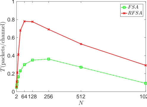
3.2 Throughput T RFSA vs FSA as function of number of nodes N . . 23
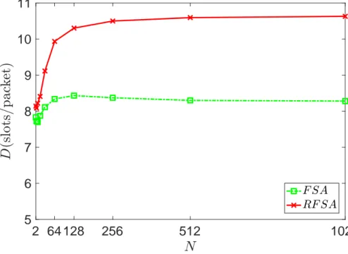
3.3 Average delay D per successfully transmitted packet RFSA vs FSA as function of number of nodes N . . . 24
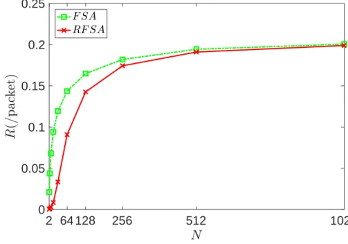
3.4 Number of retransmissions R per packet RFSA vs FSA plotted as function of number of nodes N . . . 25
LIST OF FIGURES xi
3.5 Packet Drop Probability PD RFSA vs FSA as function of number
of nodes N . . . 26
3.6 Throughput T for RFSA with respect to varying value of mean
burst length B. . . 27 3.7 RFSA average delay D with respect to varying value of mean burst
length B. . . 28
3.8 Throughput T for RFSA with respect to varying value of mean
idle time A. . . 29 3.9 RFSA average delay D with respect to varying value of mean idle
time A. . . 30 3.10 Throughput T for RFSA with respect to varying value of number
of channels M . . . 31 3.11 RFSA average delay D with respect to varying value of number of
channels M . . . 32
4.1 System Model . . . 34
4.2 Throughput T as a function of load ρ for FSA and RFSA-SP. . . 41
4.3 Blocking probability Pbas a function of load ρ for FSA and RFSA-SP. 42
4.4 Number of retransmissions R per packet as a function of load ρ for FSA and RFSA-SP. . . 43
4.5 Throughput T as a function of load ρ for FSA and RFSA-SPS4. . 44
4.6 Blocking probability Pb as a function of load ρ for FSA and
LIST OF FIGURES xii
4.7 Number of retransmissions R per packet as a function of load ρ for FSA and RFSA-SPS4. . . 46
4.8 Throughput T as a function of load ρ for FSA and RFSA-SPS8. . 47
4.9 Blocking probability Pb as a function of load ρ for FSA and
RFSA-SPS8. . . 48
4.10 Number of retransmissions R per packet as a function of load ρ for FSA and RFSA-SPS8. . . 49
4.11 Throughput T as a function of load ρ for FSA and RFSA-DP. . . 50
4.12 Blocking probability Pb as a function of load ρ for FSA and
RFSA-DP. . . 51 4.13 Number of retransmissions R per packet as a function of load ρ for
FSA and RFSA-DP. . . 52 4.14 Throughput T as a function of load ρ for RFSA-SP, RFSA-SPS
and RFSA-DP. . . 53 4.15 Throughput T as a function of load ρ for RFSA-SP and RFSA-SPU. 55 4.16 Throughput T as a function of load ρ for RFSA-DP and RFSA-DPU. 56 4.17 RFSA-SP and RFSA-DP throughput T as a function of α for ρ3 =
1/2 . . . 58 4.18 RFSA-SP and RFSA-DP throughput T as a function of α for ρ3 =
1/3 . . . 59 4.19 RFSA-SP and RFSA-DP throughput T as a function of α for ρ3 =
Chapter 1
Introduction
1.1
Overview
With the advent of the Internet of Things (IoT) and Machine-to-Machine (M2M) communications, the number of devices connected to the Internet is increasing rapidly. Sensors, actuators and RFID technologies work together to seamlessly integrate to the Internet. Advancements in Micro-Electronic-Mechanical Sys-tems (MEMS) technology, digital electronics and wireless communications have resulted in the development of small devices capable of sensing, computing and communicating over small distances. A network of these nodes is called a Wire-less Sensor Network (WSN) with a wide range of applications in industrial mon-itoring, environment monmon-itoring, infrastructure monmon-itoring, retail; see [3] and the reference therein. In [1], the authors define three paradigms for the IoT: internet-oriented (middleware), things-oriented (sensors) and semantic-oriented (knowledge). The true potential of the Internet of Things can only be unleashed in application domains where these paradigms intersect.
Access to shared channel resources is an important concern for wireless net-works. Throughput of the underlying medium access schemes can significantly af-fect the overall performance of the network. Therefore, careful design of medium
Figure 1.1: Internet of Things paradigm as a result of the convergence of different visions [1]
access schemes is vital to optimal operation of the network. Medium access schemes proposed for wired networks cannot be used for wireless networks with-out modification. A number of medium access schemes have been proposed for wireless networks in the literature. MAC protocols for wireless networks can be categorized into scheduled and event-driven protocols [4]. Schedule-based MAC protocols like TDMA, FDMA, CDMA avoid collisions by reserving resources for each node. Network resources, however, are used wastefully as every node may not use the resource reserved for it at all times. Another drawback of these proto-cols is that they are not adaptable and scalable. Low Energy Adaptive Clustering Hierarchy (LEACH) [5] and Bluetooth [6] are examples of scheduled protocols. In LEACH, nodes are organized into clusters with TDMA within each cluster man-aged by a cluster head. The role of the cluster head is rotated between nodes in the cluster to avoid uneven energy depletion. Bluetooth standard was introduced for Personal Area Networks (PAN) and organizes nodes into piconets. Piconets are clusters consisting of a master node and upto seven slave nodes. For commu-nications inside the cluster, TDMA is used and for inter-cluster commucommu-nications, frequency-hopping CDMA is used.
Event-driven protocols do not allocate channel resources for nodes in advance; instead resources are allocated to nodes when they have data to send. While
these protocols are more scalable and adaptable to changes in the network, for example the node density and traffic load, they are also prone to collisions. Other drawbacks of these protocols include idle listening and over-hearing [7]. ALOHA and its predecessors and CSMA/CA are the most prominent protocols in this category.
Introduced in 1970, ALOHA [8] was the first of its kind medium access sys-tem that provided wireless communication between different campuses of the University of Hawaii. Aloha considers a star topology with a single gateway communicating with multiple nodes. Each node performs random access without any prior knowledge about the channel to transmit its data. If only one node transmits during this time, transmission is successful, otherwise, a collision oc-curs. While Aloha offers an attractive medium access mechanism due to its low complexity its throughput is also low due to collisions. A number of variations of pure Aloha were later introduced to improve its throughput performance. Slot-ted Aloha (S-Aloha) [9] is one such scheme which divides time into slots and transmissions are synchronized according to these time slots. Each node can only transmit at the start of a time slot. This synchronization results in a reduced number of collisions and hence improves the performance of pure Aloha. Frame Slotted Aloha (FSA) [10] is another predecessor of pure Aloha which divides time into frames. Each frame consists of multiple slots. Each node randomly selects a slot for transmitting its data in a frame. Reservation Aloha (R-Aloha) [11] was proposed to improve the performance of FSA for satellite communications where long messages are fragmented into smaller packets each of which can be transmitted in one slot. It was proposed that in these scenarios if a node success-fully transmits its first packet in a slot, this slot should then be reserved for this node at the successive frames until the end of the message. This protocol im-proves the performance of FSA without increasing the overall complexity. While it was initially proposed for satellite communications, it also found applications in vehicular networks, optical networks, and other domains [12–14].
For IoT networks and M2M communications, energy conservation is one of the main concerns and hence MAC protocols need to be simple and efficient. While a number of protocols are proposed for these networks in the literature, in
practical applications, Aloha-based protocols are widely used. In a single-hop IoT network, nodes communicate with a single gateway with no direct communication taking place between the nodes. In some of these networks, nodes transmit longer messages fragmented into packets. For such networks, R-Aloha can be used as it improves the throughput without increasing the complexity.
INTERNET GATEWAY N5 N5 N4 N3 N2 N1
Figure 1.2: Single hop Internet of Things network
R-Aloha has been previously studied for M2M communications and is often referred to as Reservation Frame Slotted Aloha (RFSA). Most of these studies focus on its use as an anti-collision algorithm for tag detection in RFID and merely delta traffic conditions have been considered. IoT networks, however, are very diverse with a variety of applications with unique system and traffic models and there is a gap in the literature in terms of studying RFSA for different IoT networks. Keeping in mind this gap, we aim to study the performance of RFSA for single hop IoT networks with duty cycling. In addition, we adapt this protocol for a multi-class heterogeneous IoT network.
We study the throughput, delay and energy performance of RFSA for a duty-cycled network in which nodes have alternating idle and busy periods. During busy periods, the nodes transmit a burst of data with packets while during idle periods the transmitters are turned off. Through simulations, we compare the performance of RFSA with FSA and show that it outperforms FSA in terms of our performance metrics. In addition, we study the effect of system parameters on the throughput and delay performance of RFSA. Building on the insights gained
through these results, we then introduce a heterogeneous IoT network with nodes belonging to different classes. Nodes in class i sample data packets with a period Pi during the busy period and transmit them. As each class has a unique
pe-riod, the use of RFSA in such a network requires channel allocation schemes for distributing channel resources between these classes. We propose three different channel allocation schemes in the context of two reservation-based and one spo-radic traffic class and study their performance. More than two reservation classes of traffic is left for future research.
1.2
Literature Review
Internet of Things (IoT) is an extension to the traditional Internet which promises to let a massive number of Internet-enabled devices to exchange sensed data over the Internet. While IoT is a promising technology with substantial potential to revolutionize both our daily lives and the way we work, it poses several design challenges. The end devices in an IoT network are small battery powered nodes with very limited energy and computational resources.
Internet of Things is still considered an emerging technology but Internet-enabled devices were available in the 1990s. John Romkey [15] introduced the first known IoT device, an Internet controlled toaster in 1989. This toaster could be turned on/off using the Internet. In 1999, the term Internet of Things (IoT) was introduced by Kevin Ashton [16], executive director of the Auto-ID center, in the context of supply chain management. However, in the past decade, the definition has widened with IoT finding applications in all venues of life including health care, utilities, transport, etc. [17]. It would be appropriate to say that IoT has stepped out of its budding stage and is on the verge of enabling the fully integrated Future Internet [2]. In 2008, Cisco reported that there were more devices connected to the Internet than people and it is estimated that by 2020, there will be over 50 billion IoT devices [18]. IoT is finding applications in every aspect of our lives and soon Internet will be deeply woven into the fabrics of our daily lives blurring the boundaries between cyber and physical worlds.
Figure 1.3: Internet of Things applications [2]
IoT networks operating in the license free spectrum are subject to a variety of regulations by different regulatory authorities. One of these regulations is the maximum duty cycle limit per device. This limit has been defined to prevent a transmitter from occupying a channel for extensive period of time. The maximum duty cycle limit is in the range of 2.8 percent for devices complying with Listen Before Talk and Adaptive Frequency Agility [19]. In addition to the maximum duty cycle constraint, duty cycling is also an important concept for conserving energy of the network. A number of duty cycling algorithms [20–25] have been proposed in the literature to manage the energy consumption of nodes.
Internet of Things networks generally consist of low-power devices with low computational complexity. These devices have limited energy and computational resources, making energy efficiency the main design challenge. This tradeoff be-tween efficiency and energy consumption has led to substantial research for de-signing efficient medium access schemes for these networks. A number of MAC protocols have been proposed for IoT networks in the past. MAC protocols for IoT can be categorized into contention-based protocols, contention-free protocols and hybrid protocols [26].
Aloha [8] was the first random access scheme that proposed transmission of messages as they arrive without sensing the channel. Through the use of positive acknowledgments and checksums, this protocol allows the nodes to transmit data
in an unsynchronized manner. Due to lack of central control, there is a probability of collisions in this protocol due to which it cannot utilize the channel resources to the fullest extent. The maximum achievable throughput of Aloha is 1/2e ≈ 0.18. To improve the performance of pure Aloha, slotted Aloha [9] was proposed. In slotted Aloha, the time axis is divided into identical slots. Size of these slots is chosen to be equal to the transmission time of a single packet. Each node can access the channel at the start of a slot with a certain probability. Since there are no transmissions during a slot, the number of collisions is significantly reduced thus resulting in doubling of the throughput of pure Aloha. Frame slotted Aloha [10] is another variant of slotted Aloha which further divides into frames which are composed of a number of time slots. Each user can transmit data in a randomly chosen time slot and the decision is to be made on a per-frame basis.
Slotted Aloha and frame slotted Aloha-based protocols have found a wide range of applications in networked systems due to their low complexity and effectiveness in tackling collisions. These applications range from satellite communications [27] and wireless local area networks [28] to more recent applications such as M2M communications [29]. Frame slotted Aloha has gained a lot of attention for tag identification in RFID systems [30], [31] and is also a part of the EPCGlobal Class-1 Generation-2 (C1G2) RFID standard [32].
The work in [11] proposes R-Aloha for satellite communications with the aim of maximizing channel utilization with a low complexity medium access scheme. In satellite communications, nodes need to transmit long messages comprising multiple packets over a shared broadcast channel. The reference [33] provided a performance analysis of R-Aloha for packet broadcast networks and provides an analytic framework for characterizing the message delay and channel utilization of the protocol. A number of expressions for channel throughput and channel capacity are derived and it is shown that the channel capacity of R-Aloha ranges from that of slotted Aloha to one, depending on the input traffic and user model. While R-Aloha was initially proposed for satellite communications making use of the unique traffic patterns of a satellite network, it also found a number
of applications in other types of communication networks. In vehicular adhoc networks, R-Aloha based medium access schemes offer an attractive alternative to contention-based schemes by offering a solution to mobility issues without compromising on the QoS metrics. In [13], Reliable R-Aloha (RR-Aloha) was proposed for ad-hoc networks with hidden terminal problems. Later RR-Aloha+ [14], an extended version of the protocol was proposed which improves its stability and reliability without increasing its complexity. Other variations of RR-Aloha have been proposed and analyzed in the literature [34], [35] for improving its resilience to mobility issues facing VANETs. Reservation-based Aloha protocols offer an attractive solution for VANETs.
In [12], the authors study the use of S-Aloha based protocols, including R-Aloha for optical fiber local area networks. The study concludes that R-R-Aloha protocols are best suited for bulk data transfers in optical fiber networks and offer better throughput and delay performance then slotted Aloha. While initially the term R-Aloha was used, later many studies referred to the protocol or its variants with different names. In [36], the performance of Packet Reservation Multiple Access (PRMA) is studied with PRMA being a close relative of R-Aloha.
R-Aloha has also gained attention of researchers in IoT domain for M2M com-munications. Most of the literature in this domain refers to R-Aloha as Reser-vation Frame Slotted Aloha (RFSA). In [37], the authors study the performance of RFSA for data collection in M2M networks. In such networks, the nodes keep their radios off until prompted by a coordinator to transmit their sensed data. The study concludes that RFSA outperforms FSA in terms of its throughput, de-lay and energy performance for both the coordinator and the end nodes. In [38], the authors provide an analysis of RFSA for delta traffic conditions in which all nodes compete to access the channel at the same time setting the network into saturation. They derive an optimal frame length to maximize throughput and delay performance depending on the number of active end nodes.
Tag collision is an important issue in IoT networks which results in low recog-nition during population process of an IoT network. Aloha based protocols have also found application as anti-collision algorithms for tag identification. In [39],
the authors proposed a dynamic frame slotted Aloha (DFSA) which dynamically adjusts the number of frames in a slot according to number of tags. It over-comes the shortcomings of other Aloha-based protocols when the number of tags is large. In [40], an improvement to the DFSA algorithm has been proposed which outperforms DFSA in certain situations.
1.3
Thesis Contribution
In the literature, RFSA has been studied for IoT networks but these studies are limited to its use in tag reading and other delta traffic conditions. In delta traffic conditions, all nodes go from idle to busy mode and attempt to access the channel at the same time. While these studies conclude that RFSA outperforms FSA for such networks, there has been no work done in the past to evaluate the performance of RFSA for other IoT networks with different classes of traffic.
In this thesis, we performed a simulation study to evaluate the throughput, delay and energy performance of RFSA for IoT networks with nodes having al-ternating ON and OF F periods. During an OF F period the nodes remain idle and keep their radios off. During an ON period, on the other hand, the nodes turn on their radios and transmit a burst of data. Such a traffic model can be a realistic representation of IoT networks operating in the unlicensed spectrum where the nodes have a duty cycling constraint. In a duty cycled network nodes have an upper bound on the amount of time they can transmit. We compare the performance of RFSA with FSA in such a network.
In IoT networks, as we know there are a number of different devices working together and hence many IoT networks will not necessarily be homogeneous. In a heterogeneous network, not all nodes belong to the same class. Hence in a realistic representation of an IoT network, there are multiple classes. For using RFSA in a multi-class IoT environment, one is faced with the challenge of distributing the network resources among these classes. We propose three different schemes for dividing channel resources and compare their performance. So, the main novel
contribution of this thesis is adaptation of RFSA for a multi-class IoT network.
1.4
Thesis Outline
This thesis is organized as follows: In Chapter 2, we give some important prelim-inaries required for thorough understanding of the thesis. We discuss pure Aloha, slotted Aloha and reservation frame slotted Aloha in detail. In Chapter 3, we give a detailed overview of our system model and give the simulation results of RFSA as compared to FSA for our traffic model. In Chapter 4, we first describe our system model with two reservation-based classes and one sporadic class. Each node within a reservation-based class transmits with a period Pi during busy
pe-riods and the load on the system is a-priori known. We propose three different channel allocation schemes for this system model and study their performance as compared to FSA. We also study their performance for a wide range of system parameters and show that the choice of a channel allocation mechanism depends on the parameters of the traffic model. Finally, in Chapter 5, we present our conclusions and discuss future research directions.
Chapter 2
Related Work
This chapter provides a detailed background on the basic concepts required for understanding this thesis. First, we provide a detailed overview of pure Aloha with mathematical analysis and throughput. Next, we discuss slotted Aloha and frame slotted Aloha in detail. Frame slotted Aloha serves as our performance benchmark throughout this simulation study. And last we discuss reservation frame slotted Aloha as it forms the basis for the simulation study.
2.1
Pure ALOHA
Abramson proposed Aloha [8] as the first packet communication system designed to provide wireless access to computer systems. In 1971, the Alohanet became operational which connected different campuses of the University of Hawaii. The medium access scheme used by this network was referred to as the Aloha protocol which gained a lot of attention due to its simple nature. Aloha laid down the foundation for random access schemes which are widely studied in the literature. The simple and distributed nature of Aloha has helped in keeping it relevant to date and its variations are widely adopted in modern communication systems.
with a common gateway. Each node does not have any prior information about channel usage and transmits a packet right away as it arrives. If multiple nodes try to transmit at the same time, a collision occurs, otherwise transmission is successful. For each correctly received packet, the gateway sends an acknowledg-ment. If a node does not receive acknowledgment, it re-transmits the packet.
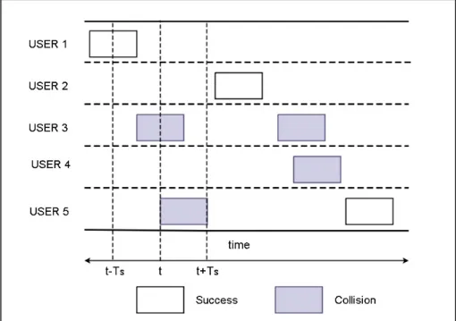
In Aloha, Ts is the transmission time of a single packet. If we consider the time
of transmission for a packet to be t, a collision occurs if any other node transmits within the t − Ts to t + Ts time interval. Since each node can transmit at any
given time so the probability of collisions is high in pure Aloha. Fig. 2.1 shows an example of such a network with 5 users. For the 5th user since the third user started transmission within t − Ts, so there is a collision. Similarly, for the third
user, the second packet also collides as the 5th user starts transmitting within the
t + Ts interval.
Figure 2.1: Packet Transmission Example pure ALOHA
Throughput T for this system can be defined as the number of successfully received packets per unit time, where a unit time can be taken as Ts. We can
define load G on the system as the number of packets transmitted per unit time. If we consider arrivals to be Poisson, then the throughput of the system is T =
Ge-2G. The maximum throughput achieved by Aloha is at G = 0.5 and is 1/2e ≈
0.18 [8]. Since the throughput of pure Aloha is very low, several variations were proposed to improve its throughput.
2.2
Slotted ALOHA
Slotted Aloha (S-Aloha) is one variation of pure Aloha which aims to improve the maximum achievable throughput through time synchronization. In S-Aloha time is divided into slots equal to the transmission time of a single packet, i.e., Ts. All nodes are synchronized by the gateway and can only transmit a packet at
the start of a time slot. In such a network, the probability of collisions goes down as nodes cannot start a transmission at any random time instant hence resulting in no partial collisions. Collisions only occur if another node starts transmission at the same time slot as this node. In Fig. 2.2, an example network for S-Aloha is given. A collision occurs for the 3rdand 5th user as they both attempt to transmit in the same time slot. For all other users, transmission is successful as no other node transmits in the same time slot.
S-Aloha increases the complexity of the system as it requires synchronization but also improves the throughput of pure Aloha. For a system throughput T is defined as the number of successfully received packets per time slot and load G is defined as the number of packets transmitted per time slot. For slotted Aloha, T = Ge-G which is maximized at G = 1 as 1/e ≈ 0.368 [9]. While the throughput for slotted Aloha is significantly higher than pure Aloha, more than 60 percent of the network time is still being wasted.
2.3
Frame Slotted ALOHA
Frame slotted Aloha (FSA) is another variation of the pure Aloha protocol. In FSA, also referred to as Framed Aloha, time is divided into frames with each frame further divided into multiple slots. FSA is similar to S-Aloha in terms of synchronization. Nodes can only start transmission at the start of a time frame. Each slot in a time frame has the size Ts. Each node can transmit in one slot per
frame. Whenever a packet arrives, the node randomly selects a slot to transmit this packet in the current frame. A collision occurs only if more than one node tries to transmit a packet in the same slot in the same frame.
Figure 2.3: Packet Transmission Example FSA
selects a slot in a frame to transmit its packet. In Frame 1, there is one collision in slot 3 as the 2nd and 4th user transmit in it. Transmissions are successful in all
other slots in all frames as only one user transmits. FSA lowers the probability of collisions by providing multiple slots within each frame to the users.
Frame slotted Aloha initially found applications in satellite communication but was later adopted for a number of communication networks including RFID tag recognition due to its low complexity and high throughput. An interesting problem in the FSA protocol is the selection of the number of slots available in a frame depending on the number of active users. A number of studies have been conducted in this regard and dynamic versions of the protocol have been proposed which optimize the number of slots available in a frame to maximize throughput.
2.4
Reservation Frame Slotted ALOHA
Reservation Aloha was proposed in 1973 with the aim to maximize channel utiliza-tion in satellite networks. In Satellite Communicautiliza-tions generally, long messages are transmitted consisting of multiple consecutive packets. The idea of RFSA is that for such communications, a node should contend for a slot in a frame only for the first packet in a long message. Once it successfully captures a slot for transmission, the slot should be reserved for this node for the entire duration of this message. So RFSA behaves as a Random Access (RA) protocol for the first packet, but for the rest of the packets in the message it behaves as TDMA.
In R-Aloha each node has information about the usage status of each slot in the previous frame. From a node’s perspective, each slot can either be used which means it was used successfully for transmission or unused which means it was either not used by any node or a collision took place. If a slot was used by node X in the previous frame it is marked as forbidden for all other nodes and node X will continue its transmission in this slot. The unused slots in the last frame are available for contention by all the nodes. There can be two variations
for this protocol, P1 with no end of usage flag and P2 with the end of usage flag. P2 offers a better throughput as no slots are wasted but P1 is simpler in terms of implementation.
Figure 2.4: Packet Transmission Example R-ALOHA
Fig. 2.4 provides a packet transmission example of R-Aloha. The users which manage to transmit a packet successfully in a slot in the given frame, reserve it for transmission in the subsequent frames. A reserved time slot is forbidden for all other users and cannot be used for transmission. As there is a collision for 2nd
and 4thusers in the first frame, no reservations are made by them. They transmit
again in the second frame and as they are successful, they reserve the time slots for the third frame.
In [33] author provided a detailed analysis of R-Aloha protocol for packet broadcast networks in 1980. In this analysis, author concludes that R-Aloha adapts itself to the nature of input traffic. The throughput of R-Aloha can range from that of slotted Aloha to 1, depending on the input traffic. While [33] provides an analysis of the protocol for two different user models, it also mentions some interesting problems that might arise in practical implementations of the protocol. In conclusion, author discusses non-homogeneous networks in which nodes can belong to different classes and how in such scenarios analysis may not be possible.
Chapter 3
Reservation Frame Slotted
ALOHA for Single-Class
Networks
In certain IoT applications, the traffic pattern is bursty with nodes having alter-nating OF F and ON times. They transmit a burst of data during the ON time and remain idle during OF F time. For such systems in which end devices need to send a burst of packets, we can enhance the performance of FSA by reserving a time slot for a node after it successfully secures a channel. The channel remains reserved for this node until the entire burst is transmitted. This scheme can be easily implemented through a forbidden list of reserved channels broadcast by the gateway. With this information, nodes can randomly select a channel from the ones not included in the forbidden list.
In this chapter, we present a system model for such a network and compare the performance of RFSA and FSA through simulations. Next, we modify different system parameters and study their effect on our performance metrics.
3.1
System Model
We consider a single hop network with a star topology. In the proposed network a single gateway communicates with multiple end nodes. Gateway is considered to have unlimited power and computational resources, however, the end nodes are battery powered with limited computational capability. No communication takes place between the end nodes. Time is divided into slots and in each time slot, multiple channels are available.
The nodes in this system model have alternating idle and busy periods. At the end of an idle period, a burst of data with multiple packets is generated. Packet sizes are such that a single packet is transmitted during a single time slot. For each node, a cycle consists of one ON period followed by an OF F period. During the ON period, a node tries to transmit the burst of data generated at its start.
Figure 3.1: Traffic Pattern for nodes
The system parameters are as follows:
• Mean burst length B, • Mean idle time A,
• Number of channels per time slot M , • Number of nodes N .
A homogeneous network comprising N nodes is considered such that all nodes have the same traffic characteristics. Burst length and idle times are geometrically
distributed with mean B and A, respectively. At the end of each idle time, a node wakes up and generates a burst of data. It now contends to secure a channel for transmitting this burst. If we define E[ON ] as the average number of time slots required for the transmission of a burst, we can write the packet generation rate R as:
R = B
A + E[ON ] (3.1)
While we have fixed the mean burst length and mean idle period, E[ON ] is not fixed and hence the packet generation rate for each node is not fixed. A node can reserve only one channel within a time slot. If a node successfully transmits a packet on a channel, that channel is reserved for this node in the subsequent slots and is marked as forbidden for all the other nodes. The channel selection algorithm is give below:
Algorithm 1: Channel Selection if First Packet of the burst then
if all channels not busy then Repeat:
Randomly select channel
if Channel not FORBIDDEN then Increment BUSY for selected channel Set CURR CHANNEL to selected channel else
goto Repeat: end if
else
Start BACKOFF Timer end if
end if
for channel selection algorithm low. Each channel is selected with an equal prob-ability. If a node wants to transmit but all the channels are reserved, it starts a BACKOF F timer which is one half the mean idle time A. Once the BACKOF F timer ends, it once again contends to reserve a channel for transmission. If the delay experienced by the first packet in the burst exceeds the mean idle time A, the burst is dropped and the node starts its OF F timer. We know that for RFSA a node can only go into backoff for the first packet in the burst, however, for FSA node can go into backoff for any packet in the burst. So for RFSA an entire burst is dropped, but for FSA a burst can be dropped in the middle. At the end of each time slot, the gateway broadcasts a Forbidden List of all the reserved channels.
3.2
Performance Metrics
In this section, we provide details of the performance metrics we will be using in this chapter to evaluate the performance of different medium access schemes.
The first and most important performance metric we will be using is the throughput T . We define throughput T as the number of successfully transmitted packets per channel where each time slot consists of M channels.
Our second performance metric is delay D and we define delay D as the average delay per successfully transmitted packet.
We will also analyze the packet drop probability PD for each protocol,where
PD is the number of packets dropped per generated packet.
Our last performance metric is the average energy consumed by a protocol. We assume that for each node Etr is the energy consumed for transmitting each packet
and R is the number of retransmissions per packet generated in the network. We take the average Energy consumption of the network to be E = Etr× R. Since
the energy consumption is directly related to the number of retransmissions per packet so we take it to be our metric of interest.
3.3
Simulation Results
We have implemented our simulator in C++. Our simulator consists of three classes: Gateway, SGateway, and N ode. SGateway class runs the simulation for our system model and given input parameters for FSA. Gateway class does the same for RFSA. We create objects of both Gateway and SGateway class. The constructor for each class takes the number of nodes N , the number of
channels M , mean burst length B and mean idle time A as input. In each
constructor, N objects of the N ode class are created and initialized with the given parameters. The constructor then calls the run simulation function which takes the N ode objects as input. Pseudo code for this function is given below:
Algorithm 2: RunSimulation
while SimTime ≤ Tmaxdo Set BU SY to zero for all channels for all Nodes do
if BACKOF F timer=0 then if OF F timer =0 then
Set new ON timer else
if OF F timer6= 0 then Decrement OF F timer else
if First Packet of the burst then if all channels not busy then
Repeat:
Randomly select channel
if Channel not F ORBIDDEN then Increment BU SY for selected channel Set CU RR CHAN N EL to selected channel else
goto Repeat: end if else
Start BACKOF F Timer end if
else
if ON Timer=1 then Set OF F Timer Release reserved channel end if Decrement ON Timer end if end if end if else
if packet delay greater than threshold then Drop burst
Set OF F timer else
Decrement BACKOF F timer end if
end if end for for all Nodes do
if CU RR CHAN N LE 6= 0 then
if BU SY ¿1 for CU RR CHAN N EL then Increment COLLISION S
Set BACKOF F timer else
Decrement ON timer if ON timer=0 then Set OF F Timer Release reserved channel else
Put CU RREN T CHAN N EL in F ORBIDDEN end if
end if end if end for end while
This function gives us the throughput, delay, packet generation rate and drop probability. We have compared the performance of our scheme with FSA. We compare the throughput, delay, packet generation rate and drop probability of both these channel access schemes. For these simulations, we take A = 10, B = 8 and M = 16 and the simulation runs for Tmax = 106 time slots. We also compare
the delay and throughput performance of our scheme for different values of A, B, and M .
3.3.1
Throughput
As we can see from Fig. 3.2, as we increase the number of nodes in the network from 2 to 1024, RFSA outperforms FSA. This graph trend is expected as with increasing load, the number of utilized time frames also increases but after a cer-tain point throughput goes down again as at the higher loads number of collisions also increases. Since in RFSA we are ensuring the availability of a channel by reserving it, the overall throughput is much better than FSA.
2 64 128 256 512 1024 0 0.2 0.4 0.6 0.8 1
3.3.2
Delay
We can observe in Fig. 3.3 that the delay experienced by each successfully trans-mitted packet in FSA is slightly less as compared to that in RFSA. This can be understood by the fact that for RFSA a burst gets dropped only if the first packet experiences a delay of more than the mean OF F time. However, for FSA if the delay experienced by any packet due to backoff exceeds A, rest of the burst is dropped. For RFSA as lesser collisions result in lesser number of bursts being dropped, it means that last packets in the burst might experience longer delays due to transmission of packets ahead of them. For FSA, since more bursts are dropped so more packets are dropped without experiencing longer delays due to transmission.
The delay for both protocols becomes stable after a point due to the backoff and dropping criteria being used.
2 64 128 256 512 1024 5 6 7 8 9 10 11
Figure 3.3: Average delay D per successfully transmitted packet RFSA vs FSA as function of number of nodes N .
3.3.3
Energy Consumption
In Fig. 3.4, we can see a plot of retransmissions per packet for both these protocols. For lower loads, the energy consumption of RFSA is much lower as compared to FSA. However, for higher loads, since the number of collisions increases for both the protocols so the number of re-transmissions becomes comparable.
2 64 128 256 512 1024 0 0.05 0.1 0.15 0.2 0.25
Figure 3.4: Number of retransmissions R per packet RFSA vs FSA plotted as function of number of nodes N .
3.3.4
Packet Drop Probability
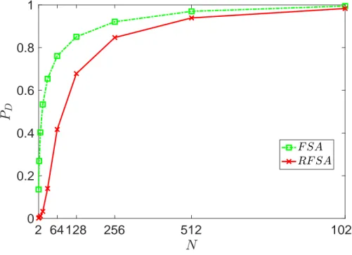
As shown in Fig. 3.5, the packet drop probability for RFSA is also much less than FSA. As the delay experienced by packets in RFSA is much less, so the number of packets exceeding the delay threshold and thus being dropped is also much less. For higher load values, the drop probability of both the protocols become comparable as the number of collisions increases at higher loads for RFSA as well.
2 64 128 256 512 1024 0 0.2 0.4 0.6 0.8 1
Figure 3.5: Packet Drop Probability PD RFSA vs FSA as function of number of
nodes N .
3.3.5
Delay and Throughput Comparison for varying A,
B and M
In this section, we compare the throughput and delay of RFSA for different values of mean ON time, mean OF F time and the number of channels.
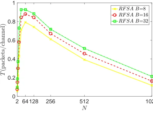
First, we compare the throughput and delay of RFSA for B=8, B=16 and B=32. As we increase the value of the mean ON time, throughput performance of our algorithm also increases. As the mean ON time increases, a node captures a channel for a longer period of time, which in turn results in increased channel utilization.
2 64 128 256 512 1024 0 0.2 0.4 0.6 0.8 1
Figure 3.6: Throughput T for RFSA with respect to varying value of mean burst length B.
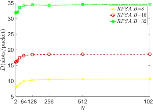
In terms of delay, however, RFSA performs worse when B increases. This result is also intuitive as increasing the time a channel remains reserved increases the amount of time packets stay in the network waiting to be transmitted. While initially, the delay performances are comparable, the difference becomes much significant for higher traffic loads.
2 64 128 256 512 1024 5 10 15 20 25 30 35
Figure 3.7: RFSA average delay D with respect to varying value of mean burst length B.
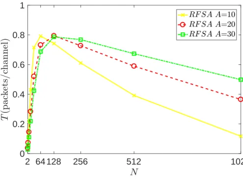
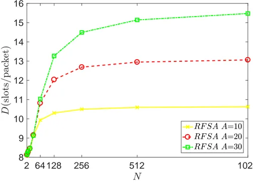
We have compared the performance of our protocol for A = 10, A = 20 and A = 30. Both the throughput and delay comparison show us that increasing A has the opposite effect as compared to increasing B in this system model. Increasing A decreases the throughput for less number of nodes as longer sleep times result in less channel utilization. However, as the number of nodes in the network increase, higher values of A mean less load on the system, which results in lesser number of collisions and better throughput.
2 64 128 256 512 1024 0 0.2 0.4 0.6 0.8 1
Figure 3.8: Throughput T for RFSA with respect to varying value of mean idle time A.
Delay performance of the protocol decreases by increasing A and the delay becomes higher at higher load values. Longer sleep times result in less traffic load which results in less delay experienced by the first packets in a burst. As this delay is less, so lesser bursts are dropped thus resulting in longer transmission delays experienced by packets. In addition as A determines the upper bound on the delay experienced due to backoff by each packet in the burst, so increasing A also increases the average delay experienced by each successfully transmitted packet.
2 64 128 256 512 1024 8 9 10 11 12 13 14 15 16
Figure 3.9: RFSA average delay D with respect to varying value of mean idle time A.
In this section, we compare the throughput and delay of RFSA for different values of M . We have fixed M =16, M =32 and M = 64 with A=10 and B=8. The results are given in figures 3.10 and 3.11. Here it is important to mention that we are taking throughput to be the number of successfully utilized frames. As for all three cases, the offered load is the same but the number of frames is higher for M = 32 and M = 64, so at lower loads their throughput is also less than M = 16. But as the load on the system increases, the number of collisions increase for M = 16 and its performance drops. The other two perform better as the number of available channels is higher and hence the number of collisions is less.
2 64 128 256 512 1024 0 0.2 0.4 0.6 0.8 1
Figure 3.10: Throughput T for RFSA with respect to varying value of number of channels M
In terms of delay, however, RFSA performs better when M = 32 and M = 64. This result is also intuitive as increasing the number of available channels de-creases the number of time packets stay in the network waiting to be transmitted. While initially, the delay performances are comparable, the difference becomes much significant for higher traffic loads.
2 64 128 256 512 1024 8 8.5 9 9.5 10 10.5 11
Figure 3.11: RFSA average delay D with respect to varying value of number of channels M .
Chapter 4
Reservation Frame Slotted
ALOHA for Multi-Class
Networks
In the last chapter, we studied the performance of RFSA for a network in which all nodes belong to a single class. In real-world scenarios, this is often not the case. In the IoT services generally, a variety of devices communicate and work together towards a common task. In such a network, a variety of devices share the channel resources for communicating with the gateway. We can model such a network as a multi-class network in which nodes belong to different classes. In this chapter, we develop a new system model for a more realistic multi-class network. We then try to adapt RFSA for such a network. In a multi-class en-vironment, channel allocation between different classes is an interesting problem for RFSA. We propose three different channel allocation schemes and study their performance as compared to FSA.
4.1
System Model
In this system model, we once again consider a single hop network with one gateway communicating with multiple end nodes. This network is different from the system model from the last chapter as the traffic patterns for all nodes is not the same. We have nodes belonging to three different classes. Two of them are reservation-based classes in which nodes transmit periodically with period Pi and
each Class-i is characterized by three parameters:
• Pi: Period of class
• OF F -time distribution in slots with mean E[OF Fi]
• ON -time distribution in super-slots with mean E[ONi]
For each reservation-based class, a super-slot is taken to be equal to Pi slots.
As we take the mean ON time in super slots, so it is always an integer multiple of period Pi of this class.
For each node, a cycle consists of one ON time followed by an OF F time. The ON time gives us the number of packets sampled by the node in a cycle. For each class, the packets are sampled with a period of Pi. We assume that a single
packet is transmitted in a single slot. The OF F time, on the other hand, specifies the number of slots this node remains idle. For each ON time a node attempts to capture a slot for transmission of the first packet. Once a slot is captured, it is reserved for the node with period Pi. If the node is unable to capture a slot
due to collision it keeps retrying for Pi slots. If it is unable to capture a slot in Pi
attempts, the packet is dropped and it performs contention for the next sampled packet.
Figure 4.1: System Model
For each class the packet generation rate for each node Ri is defined as the
number of packets generated per slot. For the reservation-based classes it can be written as:
Ri =
E[ONi]
E[OF Fi] + PiE[ONi]
(4.1) By fixing the value of E[ONi], Pi, and Ri we can find the value of E[OF Fi] for
this class. We define Ni as the number of nodes of a class in the network and
NiRi gives us the number of packets generated per slot per class. If M is the
number of channels in a slot the load ρi generated by each reservation-based class
can then be found as:
ρi =
NiRi
M (4.2)
The overall load is the sum of loads of all classes and can be written as:
ρ = P NiRi
M (4.3)
We have a third non-periodic sporadic class which generates traffic with a prob-ability ϕ. Nodes belonging to the sporadic class sample packets at a rate ϕ and do not require reservation. Each node attempts to transmit this packet and if transmission fails, the packet is dropped.
4.2
Performance Metrics:
We use three performance metrics to evaluate the performance of our algorithm namely:
• Throughput T ,
• Blocking probability Pb,
• Average energy consumption E.
We define the throughput T as the number of successful transmissions per channel.
Blocking probability Pbis the average number of packets dropped per generated
packet.
We assume that for each node Etr is the energy consumed for transmitting
each packet and R is the number of retransmissions per packet generated in the network. We take the average energy consumption of the network to be E = Etr × R.
Since the energy consumption is directly related to the number of retransmis-sions per packet we take R to be our performance metric of interest.
4.3
Algorithms:
For our study, we compare the performance of four different medium access schemes.
• Frame slotted Aloha (FSA)
• Reservation frame slotted Aloha-Static Partitioning with Sharing (RFSA-SPS)
• Reservation frame slotted Aloha-Dynamic Partitioning (RFSA-DP)
All these schemes are used for the multi-class system model as described above. Frame slotted Aloha is used as the performance benchmark as we are offering an improvement to it.
4.3.1
Reservation Frame Slotted ALOHA-SP
In RFSA-SP, we statically partition the channels for each reservation-based class. The channels reserved for one reservation-based class cannot be used by the other reservation-based class. The sporadic class selects uniformly between all the chan-nels as nodes in this class do not require a reservation. Users of each reservation-based class choose uniformly between different slots that are available to this specific class. We define C1 and C2 as the number of channels reserved for each
class is as follows:
Algorithm 3: Channel selection RFSA-SP if all channels not busy then
Repeat:
if Node belongs to Class 1 then
Randomly select channel from first C1 channels else
Randomly select channel from last C2 channels end if
if Channel not FORBIDDEN then Increment BUSY for selected channel Set CURR CHANNEL to selected channel else goto Repeat: end if else Decrement ON timer end if
4.3.2
Reservation Frame Slotted ALOHA-SPS
In RFSA-SPS, we again statically partition the channels for each class but we also let the classes share some channels. Each node first tries to capture a channel reserved for its own class. If all such channels are in use, it then tries to capture one of the shared channels. For the reservation-based class if the current channel belongs to its own class it is reserved for future use however if it belongs to the shared channels it performs contention for the next packet. The sporadic class can still select any channel regardless of whether it’s reserved for a class or shared. The channel selection algorithm used by each reservation-based class is
given below:
Algorithm 4: Channel Selection RFSA-SPS if all channels for this class not busy then
Repeat:
Randomly select channel from channels reserved for class if Channel not FORBIDDEN then
Increment BUSY for selected channel Set CURR CHANNEL to selected channel else
goto Repeat: end if
else
Repeat1:
Randomly select channel from shared channels if Channel not FORBIDDEN then
Increment BUSY for selected channel Set CURR CHANNEL to selected channel else
goto Repeat1: end if
end if
4.3.3
Reservation Frame Slotted ALOHA-DP
In RFSA-DP channels are dynamically partitioned between the classes. If a node manages to secure a channel, it is reserved for this class and nodes from the other class cannot access this channel. Reservation of a channel ends when all nodes of this class utilizing this channel complete their transmission. So the partition-ing of resources happens dynamically based on the traffic pattern. The channel selection algorithm utilized by nodes of reservation-based classes is as follows:
Algorithm 5: Channel Selection RFSA-DP if all channels not busy then
Repeat:
Randomly select channel
if Channel not FORBIDDEN and not reserved for other class then Increment BUSY for selected channel
Set CURR CHANNEL to selected channel else goto Repeat: end if else Decrement ON timer end if
The gateway in case of two reservation-based classes provides two bits of in-formation about a slot to all nodes:
• 00: The slot is available to all classes • 01: Slot is available to nodes of class 1 • 10: Slot is available to nodes of class 2 • 11: Slot unavailable
So these algorithms can easily be implemented with two-bit feedback provided by the gateway.
4.4
Simulation Setup:
For our simulations we take two classes with periods P1 and P2. We fix the packet
generation rate for each class to be R1 = R2 = R = 0.01. Our third sporadic class
the reservation-based classes to be Rp = PP21 = 16. N is the total number of nodes
in the network and there is an equal number of nodes of each class in the network i.e. N1 = N2 = N3 = N/3. Since for this system model, we know the exact load
on the network so we plot our performance metrics versus ρ. To find the number of nodes in the network for each value of ρ we put these values in Equation 4.2:
N2 =
ρM
R (4.4)
For this simulation, we vary ρ from 0.2 to 4. The parameters used for these simulations are as follows:
P1 2 P2 32 R 0.01 M 16 E[ONi] 10 Tmax 107
For each reservation-based class we fixed the E[ON ] to be 10. Putting the value of P ,R, and E[ON ] in Equation 4.1 we can find the E[OF Fi] for each class.
4.5
Simulation Results:
4.5.1
Reservation Frame Slotted ALOHA-SP
In this subsection, we study the results of RFSA with static partitioning of chan-nels among the classes. As discussed earlier, we have three classes with an equal packet generation rate of 0.01. All three classes have an equal number of nodes in the network and we vary the load in the network by changing the total number of nodes. For the reservation-based classes, we allocate an equal number of channels i.e., half of the total number of channels. Nodes from each reservation-based class
only use the channels allocated to their class. The nodes from the sporadic class are, however, free to select any channel for transmission as long as it is available in the current slot.
First, we study the throughput of RFSA-SP as compared to FSA in this multi-class network. As we can see from Fig. 4.2, RFSA-SP outperforms FSA in terms of throughput. The maximum throughput achieved by the protocol as well as the throughput at high traffic loads are better than FSA. An important point to note in this figure is that beyond ρ = 2.6, the throughput performance of RFSA-SP drops at a much higher rate. For understanding this, we must keep into account that one-third of the traffic for this system model does not benefit from the reservation, so at the higher loads performance of the algorithm drops. In addition, as at higher loads, a higher number of nodes try to access this small subset of channels, the number of collisions increases rapidly.
0.4 0.8 1.2 1.6 2 2.4 2.8 3.2 3.6 4 0 0.2 0.4 0.6 0.8 1
Figure 4.2: Throughput T as a function of load ρ for FSA and RFSA-SP.
Next, we take a look at the blocking probability for both these protocols. As we expected the blocking probability for RFSA-SP is much less than FSA. For this system model, a burst is only dropped if the delay exceeds the period of
the class. As for RFSA, the number of collisions is much less than FSA, so fewer nodes experience a delay of more than P for their first packet. Another important factor is that for FSA nodes perform contention for each packet in the burst so the probability of experiencing a delay of more than P in a burst is higher. The blocking probability for RFSA-SP increases rapidly for ρ > 2.6, as for high load as a number of collisions is higher. Since nodes of the sporadic class drop their packets upon the first collision and do not try retransmissions these packets contribute significantly to the increase in the blocking probability at higher loads. 0.4 0.8 1.2 1.6 2 2.4 2.8 3.2 3.6 4 0 0.1 0.2 0.3 0.4 0.5 0.6 0.7 0.8
Figure 4.3: Blocking probability Pb as a function of load ρ for FSA and RFSA-SP.
In Fig. 4.4, we compare the energy performance of FSA and RFSA-SP. For lower loads the energy performance of FSA and RFSA-SP is comparable but at higher loads, we can see a significant increase in the energy consumption of FSA. For ρ > 2.6, the energy consumption of RFSA-SP also increases rapidly.
0.4 0.8 1.2 1.6 2 2.4 2.8 0 20 40 60 80 100
Figure 4.4: Number of retransmissions R per packet as a function of load ρ for FSA and RFSA-SP.
4.5.2
Reservation Frame Slotted ALOHA-SPS
In this subsection, we discuss the performance of RFSA-SPS as compared to FSA as well as RFSA-SP. We try to evaluate the effect of having shared channels in our network. For these simulations we have fixed M =16. So we fix 4 and 8 channels as shared in our network and study the performance of RFSA-SPS for these shared channels to gain some insight about the effect of sharing on performance. In the shared channels, nodes from all classes are allowed to transmit their packets, but no reservations for the future slots can be made. So the reservation-based classes need to contend for each packet they transmit. For this section, we mention the number of shared channels as follows: For example RFSA-SPS4 represents
RFSA-SPS with 4 shared channels.
First, we study the throughput performance of RFSA-SPS4 as compared to
For ρ > 2.2 we see a significant drop in throughput but after the initial drop
throughput remains stable. So RFSA-SPS4 performs better than FSA for low
and high load values, but for a few values in the middle, its throughput is less than FSA. 0.4 0.8 1.2 1.6 2 2.4 2.8 3.2 3.6 4 0 0.2 0.4 0.6 0.8 1
Figure 4.5: Throughput T as a function of load ρ for FSA and RFSA-SPS4.
In Fig. 4.6 we have the blocking probability plot for RFSA-SPS4 and FSA.
The blocking probability plot follows a similar pattern to the throughput plot for these two protocols. At lower values of ρ, RFSA-SPS4 has a much less blocking
probability as compared to FSA. For some intermediate values of ρ FSA outper-forms RFSA-SPS4 but at higher loads once again RFSA-SPS4 has lower blocking
0.4 0.8 1.2 1.6 2 2.4 2.8 3.2 3.6 4 0 0.1 0.2 0.3 0.4 0.5 0.6 0.7 0.8
Figure 4.6: Blocking probability Pb as a function of load ρ for FSA and
RFSA-SPS4.
Next, we analyze the average energy consumption of RFSA-SPS4 as compared
to FSA. At lower load values the energy consumption of both the protocols is
comparable. For a few load values RFSA-SPS4 consumes more energy as
com-pared to FSA but at higher loads, its energy consumption is much less than FSA. This graph trend is similar to the throughput graph for these protocols.
0.4 0.8 1.2 1.6 2 2.4 2.8 3.2 0
50 100 150
Figure 4.7: Number of retransmissions R per packet as a function of load ρ for
FSA and RFSA-SPS4.
The behavior of RFSA-SPS4 can be easily understood. At lower load values,
the number of collisions is low, resulting in fewer retransmissions and better throughput. When load increases, we observe a sudden drop in throughput and increase in collisions and retransmissions. This sudden drop happens when the number of available fixed channels for each class is low and multiple nodes are contending to access these channels, hence resulting in collisions. Once all fixed channels are reserved, nodes now access the shared channels hence stabilizing the number of collisions and throughput of the system.
Now we compare the throughput of RFSA-SPS8 with FSA. As we increase the
number of shared channels we observe a drop in the overall throughput. This graph also follows the same trend as RFSA-SP and its throughput drops beyond ρ = 1.6. So as we add shared channels in our system and decrease the number of fixed channels, the throughput drop occurs at lower load but the drop is less. And throughput remains stable after this drop. As compared to FSA the throughput of RFSA-SPS8 is better for really low and high loads.
0.4 0.8 1.2 1.6 2 2.4 2.8 3.2 3.6 4 0 0.2 0.4 0.6 0.8 1
Figure 4.8: Throughput T as a function of load ρ for FSA and RFSA-SPS8.
In Fig. 4.9, the Blocking probability of both these schemes is plotted. This plot also follows the same pattern as the throughput plot. At low loads, RFSA-SPS8 has a much less blocking probability than FSA. As the throughput drops
at ρ = 1.6, the blocking probability increases and becomes higher than FSA. At much higher loads, however, the blocking probability of FSA is again higher.
0.4 0.8 1.2 1.6 2 2.4 2.8 3.2 3.6 4 0 0.1 0.2 0.3 0.4 0.5 0.6 0.7 0.8
Figure 4.9: Blocking probability Pb as a function of load ρ for FSA and
RFSA-SPS8.
Energy consumption for these schemes has a similar trend with RFSA-SPS8
consuming less energy at lower and higher loads but for some intermediate values FSA outperforms.
0.4 0.8 1.2 1.6 2 2.4 2.8 3.2 0 20 40 60 80 100 120
Figure 4.10: Number of retransmissions R per packet as a function of load ρ for
FSA and RFSA-SPS8.
As we increase the number of shared channels the overall throughput drops but the performance at higher loads improves.
4.5.3
Reservation Frame Slotted ALOHA-DP
In this section, we compare the performance of RFSA with Dynamic Partitioning as compared to FSA. In this algorithm, all three classes randomly select a channel from all the available channels. If a node from a reservation-based class manages to capture a channel, this channel is reserved for the nodes of the same class and nodes of the other reservation-based class cannot access it. The nodes of the non-periodic class, however, have the freedom to access any channel as long as it not in use in the current slot. In this way, nodes can select a channel for transmission if it is either reserved for their class or not in use by any class. When all nodes of one class complete their transmission over a channel, that channel is freed and can now be used by any node.
First, we compare the throughput of RFSA-DP and FSA. As we can see from Fig. 4.11, RFSA-DP does outperform FSA at both low and high load values. An important observation here is that as opposed to the static partitioning schemes there are no sudden throughput drops for this algorithm. Dynamic nature of this algorithm allows it to adapt to the traffic and hence provide a stable throughput.
0.4 0.8 1.2 1.6 2 2.4 2.8 3.2 3.6 4 0 0.2 0.4 0.6 0.8 1
Figure 4.11: Throughput T as a function of load ρ for FSA and RFSA-DP.
Blocking probability plot shows us that RFSA-DP has less blocking probability than FSA at all load values. While there is a significant difference between the blocking probabilities of the two protocols at lower load values, this difference reduces at higher load values.
0.4 0.8 1.2 1.6 2 2.4 2.8 3.2 3.6 4 0 0.1 0.2 0.3 0.4 0.5 0.6 0.7 0.8
Figure 4.12: Blocking probability Pb as a function of load ρ for FSA and
RFSA-DP.
In Fig. 4.13, we compare the energy performance of FSA and RFSA-DP. For lower loads the energy performance of FSA and RFSA-DP is comparable but at higher loads, we can see a significant increase different between the energy consumption of the two protocols. The number of collisions is less for RFSA-DP, which results in a lesser number of retransmissions.
![Figure 1.1: Internet of Things paradigm as a result of the convergence of different visions [1]](https://thumb-eu.123doks.com/thumbv2/9libnet/5994875.126016/15.918.314.655.166.448/figure-internet-things-paradigm-result-convergence-different-visions.webp)