17
PV PENETRATION EFFECT FOR REGULATING VOLTAGE USING REACTIVE POWER Ali Majid NOOR1
1School of Engineering and Natural Sciences, Altinbas University, Istanbul-Turkey
[email protected] Osman Nuri UÇAN2
2School of Engineering and Natural Sciences, Altinbas University, Istanbul-Turkey
[email protected] Oğuz BAYAT3
3School of Engineering and Natural Sciences, Altinbas University, Istanbul-Turkey
Abstract
Power Networks have two major aspects one is the Safety of the network and the other is its economic, reac-tive power is the very important element to serve these two aspects. To avoid unwanted power quality and high transmission loss we should locate reactive power in reasonable way in power network. Currently, in order to keep the network voltage in acceptable range and the real power loss as minimum we use dispatch of reactive power in traditional way.
Since the reactive power has inequality constrains and quality constrains, so we can consider it as a nonlinear problem. In my thesis, I will use MATPOWER 5.1 toolbox, PSO algorithm and matlab program and applied it to find the optimum reactive power dispatch allocation. The algorithm PSO is a comprehensive optimization algo-rithm that is equipped with the best searching ability. Advantage (major ones) of the PSO is that when the func-tion of the object is more complex the efficiency of PSO does not effect. Because MATLAB toolbox is a global prog-ram and our work focus on power flow so we will use MATPOWER 5.1 as open source to solve the problem. Since MATPOWER Toolbox is a power source so when any one use it, it will help him and the code will be very easy. Also we will use OpenDSS program via MATLAB COM to see PV effect.
Then we will discuss the effect of PV residential penetration via MATLAB simulation using 24 house examples with PV and without PV penetrations.
Our goal is to minimize power loss in transmission lines and to allocate the reactive power in optimal placement. IEEE 24 bus system is used to calculate the performance.
18
REAKTİF GÜÇ KULLANARAK GERİLİM DÜZENLEMESİNDE PV PENETRASYON ETKİSİ Özet
Reaktif güç, güvenlik ağızlarının ve ekonomik yüzlerin güç şebekelerinin çalışması için kritik öneme sahiptir. Re-aktif gücün mantıksız dağılımı, güç şebekelerinin güç kalitesini ciddi şekilde etkiler ve iletim kaybını arttırır. hali-hazırda, reel güç kaybını en aza indirgemenin en ekonomik ve pratik yaklaşımı, reaktif güç dağıtım yöntemi kul-lanılarak kalmaktadır.
Reaktif güç dağıtımı problemi doğrusal değildir ve eşitlik kısıtlamaları ve eşitsizlik kısıtlamaları vardır. Bu tezde, reaktif güç dağıtımı problemini çözmek için PSO algoritması ve MATPOWER 5.1 uygulanmıştır. PSO mükemmel arama yeteneği ile donatılmış küresel bir optimizasyon tekniğidir. PSO’nun en büyük avantajı, PSO’nun verimliliği-nin nesnel işlevin karmaşıklığına daha az duyarlı olmasıdır. MATPOWER 5.1, güç akışı problemlerini çözmeye odak-lanan açık kaynak MATLAB kodudur. MATPOWER’ın faydası, kodunun kolayca kullanılması ve değiştirilebilmesidir. Anahtar Kelimeler: PV, Yenilenebilir Enerji,PSO, Gerilim regülasyonu ,Reaktif güç.
1. INTRODUCTION
Power networks operation have two major aspects 1-safety and 2-economic and both of these aspects are critical to reactive power. Rational reactive power dispatch scheme can improve the power quality as well as reduce the real power loss. On the antithesis, if the reactive power is unreasonably allocated, then it will bring great economic losses and might even threaten the security of the power grid. There are many reactive compensation techniques the generator outputs power both real and reactive power Since the system has no capacitor in it, the generator will take the whole encumbrance of both the needed real power loads and desired reactive power loads. reactive power losses can be achieved which is very high by this method the next method is connect the capacitors in parallel with the loads. This approach can be further done through single power factor correction, multi power factor correction, and bulk power factor correction The disadvantage of this method is that the shunt capacitors are not fully utilized all the time. The third power factor correction method is called bulk power factor correction, as depicted in. The shunt capacitor bank is in charge of the whole system, and it is directly connected to the main bus. Since most of the loads in the electric power systems are inductive loads, they will consume large amo-unts of reactive power. The reactive power has to be obtained from somewhere in the network. If all the reactive power is produced from one place, then the real power loss will be enormous. This conclusion is demonstrated in shows both real power (W) loss and reactive power (VAR) loss is much greater than the previous two schemes. Therefore, the principle of reactive power dispatch is compensating reactive power at where the loads consume. the reactive power is showing the status of dispatch and compa-res different global dispatched methods. A code modified using MATPOWER utilizing algorithm particle swarm optimization is expanded to find a solution for the reactive power VAR dispatch problem in AC power systems, also adding 10kw to 123 bus system example was modified to see how much PV can we added to it using OpenDSS , and 24 houses as simulation examples.
19
The expected contribution in kind of this thesis mainly focuses on the following aspects:
1. When applying the algorithm of the particle swarm optimization (PSO) to regulate the values of cont-rol variables (voltage magnitudes, shunt capacitance, and tap positions) in the power networks in order to make the real power as less as much as possible.
2. Determination the optimal placement in an existing power system of a new installed PV residential. 3. Introducing MATPOWER 5.1 toolbox to calculate the power flow and manage the equality constraints in the reactive power dispatch problems.
4. Finding no. of max PV that can be added to 123 bus examples while P.U V within 1.05 and 0.95 P.U 5. Shows the voltage balance when using residential PV for 24 house examples.
2. FEEDER DESCRIPTION DISTRIBUTION
Initially, all power systems are designed and has protected for power flow for one direction from the plant power generation or low voltage side of transformer to the end user. When large amounts of DG added, it may cause bi-directional power flow changing this conventional form might cause problems in voltage or current harmonics to other customers on the distribution feeder. When connecting the PV’s to the operating grid many challenges appear such as PV variability and PV intermittency. The line-loading violations and the steady-state over-voltage are the common interest of the interconnection of these systems. The photo voltaic can also affect issues in power system such as voltage regulation equ-ipment, system losses, harmonics, voltage flicker, and protection.
We can guess that Photovoltaic (PV) injection power will part of the most Promising sectors of the energy mix interconnection. Residential and rural rooftop PV and small PV plant – especially- are the fastest gro-wing sector and a lot of voltage and power residential distribution networks already have over 25% pe-netration of photo voltaic generated power in many countries .This fast growth rate is exceeds use inter-connection standards of power grids, which consider the small rooftop PV units to be of trivial size, if we consider a group of photo voltaic in low- and medium-voltage distribution networks it will beginning to refer to a number of stability and power quality problems. One possible solution in power system to minimize the problems happened by a lot of PV is to use the additional reactive power VAR capacity of their grid-tie PV inverters grouped to strengthen the distribution power network voltage as a whole [1-4].
3. HELPING TOOL {OPENDSS}
Open Distribution System Simulator (OpenDSS or as a short name: DSS) is an inclusive power electric network system simulation tool for electrical helping tool distribution systems and grids. OpenDSS in-dicates to the open source enforcement of the DSS program. It is executed as a stand‐alone executable file program and an in process COM server DLL designed to be driven from several of existing software platforms agenda. The implemented version have a basically text‐based user interface on the solution engine to help users in developing and coding scripts and viewing results.
20
This software giving backup approximately all RMS steady-state (i.e., frequency domain) analyzes com-monly execute by user for utility systems distribution planning and analysis. Furthermore, it supports se-veral of the newest types of analyzes that are designed to meet future power grids requirements, many of which are being transcription by cancel restriction of all worldwide utilities and the advent of the “smart grid”. Many of the features which will be found in the program were basically wished to support rene-wable distribution generation analysis requirements. Other features on the other hand support energy efficiency analysis of power transport and delivery, applications of smart grid, and harmonics analysis. The DSS is designed to be indefinitely expandable so that it can be not tough modified to meet future requirement. [7].
4. EXAMPLE OF 24 HOUSES WITH AND WITHOUT PV PENETRATIONS TO SEE THE EFFECT OF VOLTAGE REGULATION
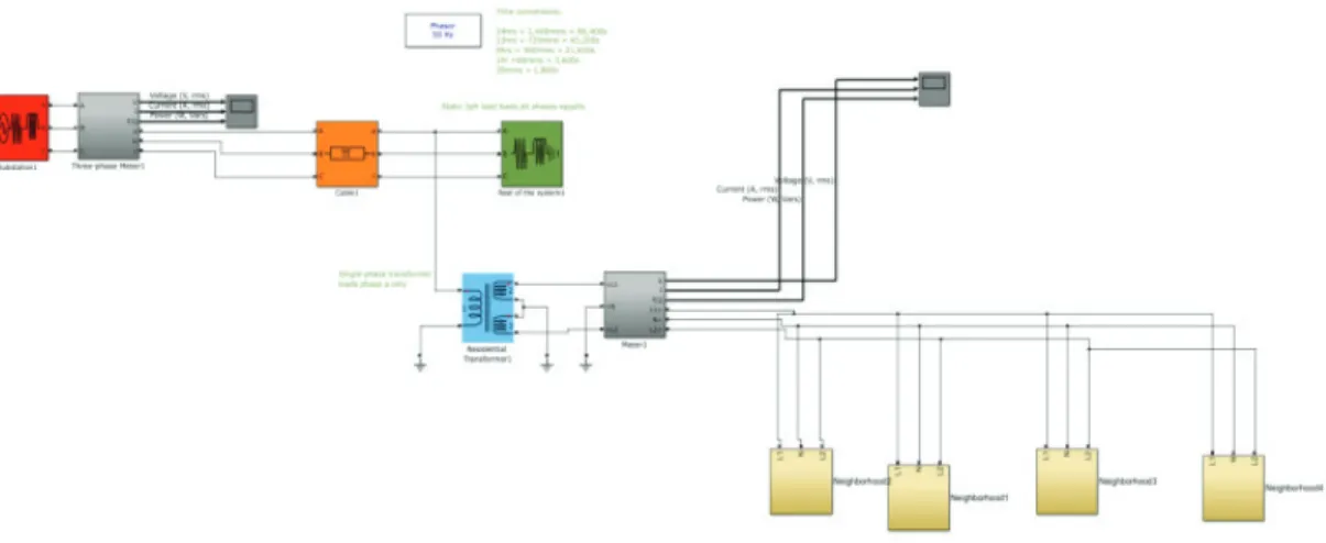
In this example we will use a simulation example which is authors at the Center for Electro mechanics of The University of Texas at Austin, we modify it by adding new 12 houses to the grid and also by using the houses with and without PV as input additional power [5-19].
Figure 1. The block diagram of overall control strategy for the proposed hybrid alternative energy system Run Example and Get Results Without PV
21
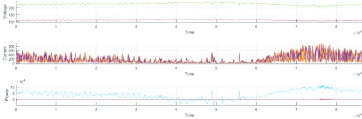
The figure above shows the total power consumed by each of the 24 houses house for 24 hour and it shows that the peak hours between 14 to 21. We can notice that the Vrms is decreased in peak hours of the day, also the current will be so high at the same time and the power consumed by the network is very high.
Run Simulatıon Wıth PV Panel Installed on Residential Houses
We can see that the power consumed from utility grid is decrease for the houses uses PV. We can no-tice that the Vrms is increased in peak hours of the day, also the current will be normal at the same time which leads to less real power loss and the power consumed by the network is normal
Figure 3a. Main grid voltage and power drawn with PV Adding PV power to 123 bus example and 24 bus
We will use 123 bus example from OpenDSS and we will study the effect of adding PV power to this net-work, we will see how much PV could be added to the network with acceptable voltage and how much losses will be decreased, we will add 10 kw as real power to the network each iteration as the flow chart shown below describes.
22
The figure shown above shows that when we adding the 10KW power PV to the 123bus example the maximum amount of PV can be added is about 1620KW PV which this number decrease the total losses to minimum, but when we add more PV’s the power losses start to increase again
Figure 4. Power loss VS Total PV added
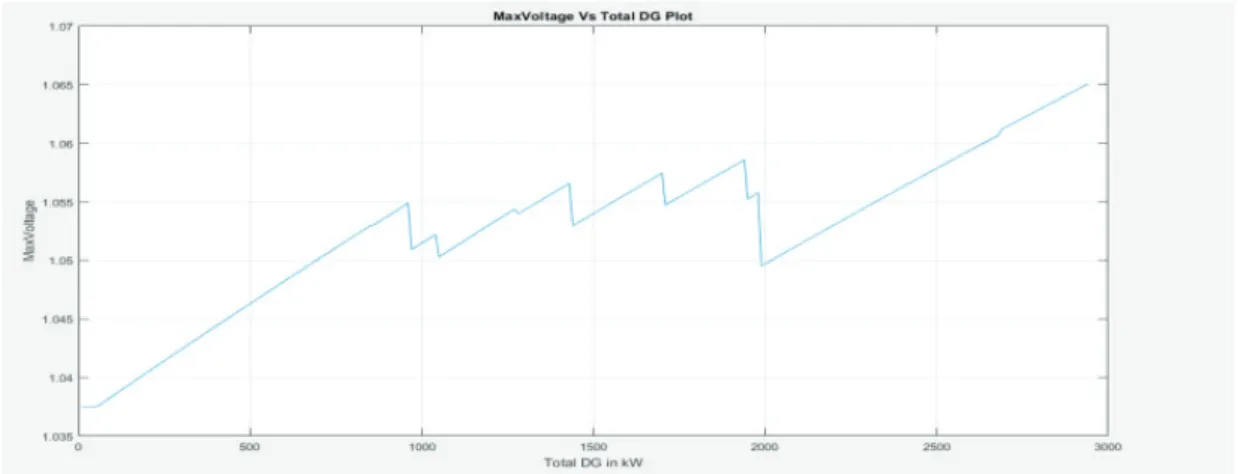
The figure shown below shows that when we add 10KW power PV to 123bus example the maximum amount of PV can be added is about 2000 KW PV which this number maintain the P.U voltage within ac-ceptable range 1.05 PU, but when we add more PV’s the P.U starts to increase.
Figure 5. Max voltage VS total PV added 5. PSO 24-BUS REACTIVE POWER FOR VOLTAGE REGULATION
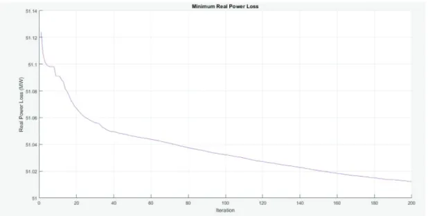
In this part of paper , we will use PSO optimization to allocate the reactive power dispatched first without using PV’s, then with the use of PV’s. First we can see that the real power loss decrease at the beginning of optimization from 51.13MW to the value of 51.0MW at iteration 100 as shown in figure 6.
23 Figure 6. 24 bus PSO reactive power dispatch without PV’s
Then when we add PV’s to the system to bus 4 the real loss decrease to 50.12MW as shown in fig 7
Figure 7. 24 bus PSO reactive power dispatch with PV’s 6. CONCLUSION
Results discussion: in chapter three when we use the 24 houses simulation we found that when we use the simulation without adding PV’s to the grid that the power consumed by the houses is completely from the utility grid which cost too much money and cause a voltage drop at peak hours. But when we
24
add PV’s to the system the voltage become smoother and the power consumed at peak hours by ho-uses is decreased which lead to less depending on the main grid to support reactive power in order to control voltage at the user end. When we run power flow for 123-bus example we can see that the po-wer loss of the total lines are 95.8 KW and when we start adding PV’s to the network at bus 83 the loss decrease to 63.7 kw also the voltage at some points raised from 0.98p.u to 1.02p.u which shows that ad-ding PV’s to the network decrease real power loss.
But we notice that when the PV’s penetrations are more than 1610kw the real power loss will start to increase again, so we should not increase more at one bus. Also the voltage increased from 0.95p.u to 1.05p.u when PV’s around 1000kw but when its more the p.u voltage become more than 1.06p.u for one bus. There are two optimization algorithms one of them run the power flow and reallocate the classic re-active power compensator, when we use the algorithm the real power loss decrease from 51.13MW to 51.02MW which save money and life time of the equipment, also when we run the algorithm with ad-ding PV power to bus 4 as an example {50 KW} the real power loss decrease from 50.2MW to 50.12MW which shows to us the benefit of using PV’s instead of traditional compensators such as capacitors, when we use renewable resources we will save money.
7. REFERENCES
A. M. Chebbo, M. R. Irving, M. J. H. Sterling, “Reactive power dispatch incorporating voltage stability,”
IET Proceedings on Generation, Transmission and Distribution, 1992
R. Thomas, T. Mount, R. Schuler, W. Schulze, R. Zimmerman, D. Shawhan, and D.Toomey, “Markets
for reactive power and reliability: A white paper,” Eng. Econ.Elect. Research Group, Cornell Univ., Ithaca, NY.
J. Hanger, P. Adels, “Reactive Power and the Blackout,” Available:
http://www.energycentral.com/artic-les/article/529
U.S. Energy Information Administration, “How much electricity is lost in transmission and distribution in the United States?” Available: http://www.eia.gov/tools/faqs/faq.cfm?id=105&t=3
http://www.mathwork.com
J. Kepka, “Reactive Power Compensation.” Wroclaw University of Technology.
N. M. Neagle, D. R. Samson, “Loss Reduction from Capacitors Installed on Primary Feeders,” Transaction of
the American Institute of Electrical Engineers, Power Apparatus and Systems, Part III, Vol. 75, Issue 3, 1956.
J. A. Momoh, S. X, Guo, E. C. Ogbuobiri, and R. Adapa, “The quadratic interior point method solving
power system optimization problems,” IEEE Transaction on Power System, vol. 9, no. 3, 1994.
R. Dubey, S. Dixit, G. Agnihotri, “Optimal Placement of Shunt Facts Devices Using Heuristic
Optimiza-tion Techniques: An Overview,” Fourth InternaOptimiza-tional Conference on CommunicaOptimiza-tion Systems and Net-work Technologies (CSNT), 2014.
25 T. Sousa, J. Soares, Z.A. Vale, H. Morais and P. Faria, “Simulated Annealing metaheuristic to solve the
optimal power flow,” IEEE Power and Energy Society General Meeting, 2011.
M. Gitizadeh, M. Kalanar, “Multi-objective fuzzy based reactive power and voltage control in a
distribu-tion system using SA,” 11th Internadistribu-tional Conference on Hybrid Intelligent Systems (HIS), 2011.
Padhy, N.P.; Abdel-Moamen, M.A.; Praveen Kumar, B.J., “Optimal location and initial parameter
set-tings of multiple TCSCs for reactive power planning using genetic algorithms,” IEEE Power Engineering Society General Meeting, 2004.
A. Parizad, M. Kalantar, A. Khazali, “Application of HAS and GA in Optimal placement of FACTS
De-vices Considering Voltage Stability and Losses,” International Conference on Electric Power and Energy Conversion Systems, 2009.
“Artificial neural network,” Available: https://en.wikipedia.org/wiki/Artificial_neura l_network
K.H. Abdul-Rahman, S.M. Shahidehpour, M. Daneshdoost, “AI approach to optimal VAR control with
fuzzy reactive loads,” IEEE Transactions on Power Systems, Volume: 10, Issue: 1, 1995.
Chao-Rong Chen, Hang-Sheng Lee, Wenta Tsai, “On-line Optimal Shunt Capacitors Dispatch of Peak
Power Systems,” IEEE/PES Transmission and Distribution Conference and Exhibition: Asia and Pacific, 2005.
E. Liu and J. Bebic, “Distribution system voltage performance analysis for high-penetration photovoltaics,”
NREL/SR-581-42298, Tech. Rep., 2008. [Online]. Available: http://www1.eere.energy.gov/ solar/pdfs/42298.pdf “IEEE 1547 Standard for Interconnecting Distributed Resources with Electric Power Systems.” [Online]. Available: http://grouper.ieee.org/ groups/scc21/1547/1547 index.html
M. Baran and F. Wu, “Network reconfiguration in distribution systems for loss reduction and load