Application of ultrasonic vibrations for minimization of
the accumulation of limescale in steam irons
This is a post-refereeing final draft. When citing, please refer to the
published version:
H. Koruk, M. Serenli, K.Y. Sanliturk, Application of ultrasonic
vibrations for minimization of the accumulation of limescale in steam
irons,
Applied
Acoustics
135,
22-28,
2018.
Application of ultrasonic vibrations for minimization of the
accumulation of limescale in steam irons
Hasan Koruka,*, Muzaffer Serenlib, Kenan Y. Sanliturkc
aMEF University, Mechanical Engineering Department, 34396 Istanbul, Turkey bSilter İleri Ütüleme Sistemleri Sanayi ve Ticaret Ltd. Şti., Büyükçekmece, 34535 Istanbul,
Turkey
cIstanbul Technical University, Mechanical Engineering Department, 34437 Istanbul, Turkey
E-mails: a[email protected], b[email protected], c[email protected] *Corresponding Author: Hasan Koruk
Abstract
The accumulation of limescale in steam irons can significantly reduce the ironing efficiency. It is
this problem that inspired us to introduce ultrasonic vibrations to irons in order to minimize
limescale accumulation. This study describes a methodology for designing, modelling and
optimizing an iron fitted with an ultrasonic exciter in an attempt to minimize limescale
accumulation. In our methodology, first, an experimental demonstration of the potential benefits of
ultrasonic vibrations in steam irons was conducted, using two existing irons, one of which was
equipped with an ultrasonic exciter. Having confirmed the benefits, an experimental iron was
designed and then optimized to maximise ultrasonic vibrations using finite element analyses within
a predefined frequency range. To validate the results of the finite element analyses, a prototype iron
base was built, and forced vibrations of this prototype, at ultrasonic frequencies ranging from 35 to
40 kHz, were measured using a laser vibrometer. The results of the theoretical and experimental vibration analyses as well as the physical experiments on the steam irons indicate that it is
possible for ultrasonic vibrations to be utilized in irons to minimize the accumulation of
limescale.
Keywords: ultrasonics; ultrasonic cleaning; limescale; steam iron; finite element model; laser
1. Introduction
Steam irons are used in almost every home for removing wrinkles from clothes. However, when
the water in an iron evaporates, calcite (calcium carbonate) tends to form a layer of limescale on
various surfaces, such as in the steam generating chambers and on the surfaces of the steam
passageways. This leads to inefficiencies in performance. Understanding how to minimize
limescale accumulation in devices and machines, including both domestic and industrial steam
irons, is an ongoing challenge [1]. Ultrasonic vibrations are being used in many existing
technologies [2-10], for cleaning surfaces, such as on 3D printed objects [11] and during water
filtration [12]. The inspiration for using ultrasonic vibrations in irons to minimize the accumulation
of limescale arose from observing the existing diverse technologies and applications that use
ultrasonic vibrations, especially for cleaning processes.
Although the analytical prediction of the dynamic properties of complex structures, especially at
ultrasonic frequencies, is quite difficult, it is possible to use finite element analyses to design and
optimize the ultrasonic vibrations of such complex structures [13]. However, finite element models
often need to be followed by experimental verifications. Laser Doppler vibrometers, on the other
hand, are capable of measuring the ultrasonic vibrations of complex structures, and can therefore
be used to provide the necessary experimental verifications [14]. The literature contains a number
of studies which have drawn upon finite element analysis and laser Doppler vibrometry when
designing ultrasonic technologies. For example, Waldron et al. [15] used finite element analysis and
laser Doppler vibrometry to identify damage in beams. Vasiljev et al. [16] utilized finite element
simulations and laser Doppler vibrometers to design an ultrasonic system for solar panel cleaning.
Furthermore, Yin et al. [17] recently used finite element methods to simulate an ultrasonic de-icing
process.
This paper presents a methodology for designing, modeling and optimizing a steam iron to
vibrate within a predefined ultrasonic frequency band so as to minimise the accumulation of
literature, which deals with modelling and optimizing ultrasonic vibrations in irons which includes
prototyping and testing. The main objectives of this study are: (i) to use experimental demonstration
to show that the use of ultrasonic vibrations in steam irons can reduce the accumulation of
limescale; (ii) to design and optimize a steam iron base with an appropriate ultrasonic exciter using
finite element analyses; and (iii) to create a prototype of the optimised iron base from which to
measure the forced vibrations at ultrasonic frequencies in order to validate the design.
2. Designing an ultrasonic steam iron
Ultrasonic vibrations are already being used in ultrasonic cleaning to remove contaminants
[11]. By utilising the same principles, we believe that ultrasonic vibrations can be used in steam
irons to minimize the accumulation of limescale. However, when designing an ultrasonic iron,
various challenges need to be overcome. For example, one must ensure that the ultrasonic vibrations
do not cause discomfort to the end user. The vibration-induced noise should not be audible to the
user, therefore, the frequency of vibrations must be higher than 20 kHz, the upper limit of the
audible frequency range for humans. Moreover, the ultrasonic exciter used to create vibrations
within the iron must be small enough to be installed directly, but powerful enough to create the
necessary vibrations. Furthermore, as the exciter contains sensitive components, i.e., piezoelectric
ceramics, it must be protected against excessive temperatures.
2.1 Preliminary ultrasonic iron design
In order to develop an “ultrasonic iron” with its own ultrasonic exciter, a preliminary design
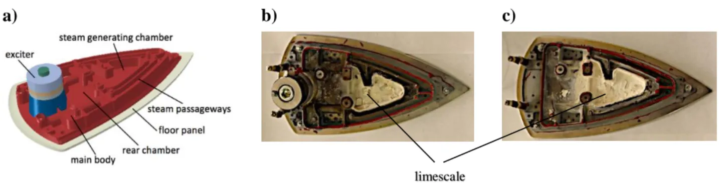
based on a typical steam iron was created. The design comprised the main body of an iron,
including a steam generating chamber, steam passageways and rear chamber, as well as a floor
panel with an added ultrasonic exciter, shown in Fig. 1a. A prototype of this ultrasonic iron was
built and experiments conducted to verify the expectation that ultrasonic vibrations are indeed
beneficial in reducing the accumulation of limescale. Physical experiments were carried out using
was a total of ten hours a day over a four-week period. During these experiments, the ultrasonic
exciter was set at around 35 kHz. At the end of the experimental period, photographs of limescale
accumulation in both irons were taken. These are presented in Fig. 1b and c. In these photographs,
one can clearly observe there is significantly less limescale on the surfaces of the iron which were
exposed to ultrasonic vibrations (approximately 32 % less).
a) b) c)
Fig. 1. The preliminary ultrasonic iron design, including the main body of the iron, floor panel and
exciter (a); photograph of limescale accumulation for the iron with ultrasonic excitation (b); and
photograph of the iron without ultrasonic excitation (c) taken after the experiments.
Having obtained experimental evidence that ultrasonic vibrations can indeed decrease the
accumulation of limescale in steam irons, we decided to optimise the dynamic behaviour of the iron
structure so as to generate effective ultrasonic vibrations at the specific locations where limescale
had been seen to accumulate. To do this, a finite element model of the prototype ultrasonic iron was
developed so its modal behaviour could be predicted at ultrasonic frequencies. The ultrasonic
exciter in the iron was modelled using 20-noded solid elements, and the main body of the iron and
the floor panel were modelled using quadratic 10-noded solid elements. This initial finite element
model consisted of around 540k elements and 930k nodes in total. Each individual part was
assumed to be “welded” to the matching surfaces. After the model creation, the eigenvalue problem
given by
K𝛟 = 𝜔2M𝛟 (1) limescale
was solved to determine the natural frequencies, 𝑓𝑖 =𝜔𝑖
2
2𝜋 and mode shapes, 𝛟𝑖 of the iron assembly.
Here, K and M are the stiffness and mass matrices of the iron assembly, respectively, and i denotes
the mode number.
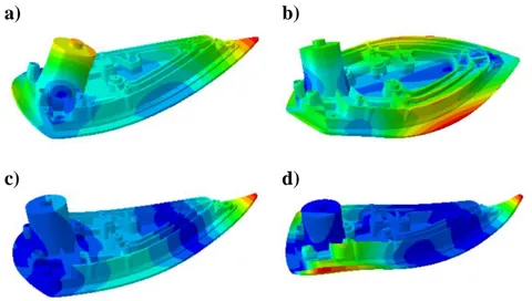
The finite element model predicted 170 modes up to 40 kHz and the first four mode shapes of
the iron are presented in Fig. 2, the corresponding natural frequencies being f1 = 1223 Hz, f2 = 1785
Hz, f3 = 2298 Hz and f4 = 3785 Hz, respectively. From these analyses, it became clear that the
lowest natural frequencies, other than those for the rigid body modes, were much lower than the
lower limit of the ultrasonic frequencies.
a) b)
c) d)
Fig. 2. The first four mode shapes of the preliminary ultrasonic iron (a-d) which were predicted
using the finite element model.
The natural frequencies predicted by this model at ultrasonic frequencies and the corresponding
mode shapes were also examined. For the purposes of illustration, some of the mode shapes with
natural frequencies greater than 30 kHz are presented in Fig. 3. The predicted results of the
preliminary design indicated that the mode shapes at ultrasonic frequencies mostly comprised local
modes due to local flexibilities in the iron structure. It is worth restating that the main purpose here
generating chamber where water droplets evaporate and turn into steam, on the surfaces of steam
passageways, and in the rear chamber. Examination of the mode shapes of the preliminary design
indicated that this design needed to be improved in order to create effective ultrasonic vibrations at
the desired locations in the iron. Consequently, we decided to revise and optimize the current iron
structure to create more effective ultrasonic vibrations in order to achieve less limescale
accumulation.
a) b)
c) d)
Fig. 3. Sample mode shapes at ultrasonic frequencies predicted using the finite element model:
(a) f = 31.1 kHz, (b) 32.6 kHz, (c) 34.2 kHz and (d) 39.3 kHz.
2.2 Optimization of the ultrasonic iron for effective ultrasonic vibrations
Undoubtedly, the most critical component of an ultrasonic iron is the ultrasonic exciter.
Therefore, the exciter must be designed, carefully analysed and skilfully incorporated into the
overall iron structure. In this investigation, we designed a piezoelectric-type ultrasonic exciter with
a working frequency range of 35-40 kHz. A thermal isolator between the piezoelectric ceramics and
the iron surface was placed to avoid excessive heating of the piezoelectric exciter. A conical-shaped
part was used to assemble the piezoelectric ceramics with the ceramic thermal isolator, and the iron
provide input electrical energy to the piezoelectric ceramics. The material properties of all these components are listed in Table 1, including Young’s modulus (E), density (), and Poisson’s ratio ().
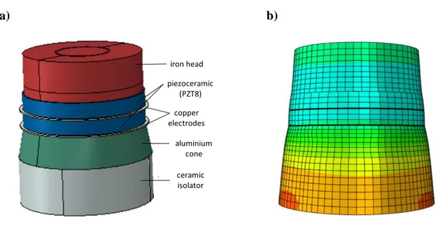
Once the physical design was completed, a finite element model of the exciter was created in
free-free conditions to predict the natural frequencies and mode shapes of the exciter system. Using
the finite element analysis, the ultrasonic exciter was tuned so as to set its first natural frequency in
correspondence with the “tension-compression” mode to be sit as close as possible to the desired
working frequency. The tension-compression mode, which was predicted at 38.2 kHz, is shown in
Fig. 4b. With this information, a prototype of the ultrasonic exciter was built. When tested, using
the impedance test method, the natural frequency of the exciter was identified as 37.8 kHz.
a) b)
Fig. 4. (a) The model of the piezoelectric exciter with ceramic isolator and (b) its first
tension-compression mode at f = 38.2 kHz predicted using the finite element model.
iron head copper electrodes piezoceramic (PZT8) ceramic isolator aluminium cone
Table 1
Material properties of the components of the piezoelectric exciter.
Component E (GPa) (kg/m3) Iron head 178.5 7113.6 0.30 Piezoelectric ceramic (PZT8) 72.7 6840.0 0.31 Copper electrode 93.5 8171.5 0.30 Aluminium cone 59.5 2462.4 0.33 Ceramic isolator 90.0 2869.3 0.31
The next step was to incorporate the ultrasonic exciter into the iron and then optimize the iron
structure to create effective vibrations at ultrasonic frequencies. Thermal aspects of the iron’s
materials were taken into account. Then the materials for the main body and floor panel were
selected to be Etial 150 and Al 6082, respectively. Young’s modulus, density, and Poisson’s ratio for these aluminium-based materials are E = 70 GPa, = 2950 kg/m3 and = 0.33. As presented in
the previous section, the preliminary design was not quite right, as it was not creating effective
ultrasonic vibrations in the steam generating chamber, steam passageways, or the rear chamber.
During observations that the central part of the steam iron did not vibrate effectively at ultrasonic
frequencies (Fig. 3) and, as seen in Fig. 1b, this was leading to the accumulation of limescale there.
In order to rectify this, the preliminary design needed to be modified to improve vibrations at
ultrasonic frequencies within the iron in the areas where limescale was accumulating. It should be
noted that any reduction in the thickness of the main body adversely affects the heat capacity of the
iron, and this may lead to undesirable vibrations below ultrasonic frequencies. Due to this, we
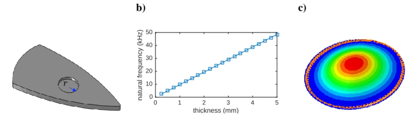
decided to create a circular plate section on the iron body, as illustrated in Fig. 5a, so as to
maximize the ultrasonic vibrations at desired locations in the iron while keeping the heat capacity of
the iron almost unchanged. We decided on the location of the circular plate by taking into
consideration from where the water in the iron is injected or sprayed onto the hot base plate to
generate steam. The initial thickness and the radius of the circular plate yielding the desired natural
frequency were predicted using an analytical model which assumed rigid boundary conditions. The natural frequency, 𝑓, was determined using
𝜆2 = 2𝜋𝑓𝑟2√𝜌ℎ
𝐷 (2)
where r and ℎ are the radius and thickness of the plate, 𝐷 is the flexural rigidity of the plate, and 𝜆2
is a frequency parameter given in the literature for different ℎ/𝑟 values [18]. The flexural rigidity is given by
𝐷 = 12(1−𝜐𝐸ℎ32) (3)
The natural frequencies estimated via this simple analytical approach, for r = 15 mm and for
different thickness values of the circular plate, are plotted in Fig. 5b. This shows that a circular plate
with a thickness of 4 mm and a radius of 15 mm is suitable for the targeted frequency range (i.e.,
35-40 kHz). Before creating a finite element model for an iron with a specified circular plate
section, natural frequencies of a circular plate with rigid boundary conditions predicted by
analytical approach were compared with the finite element predictions using shell and solid
elements. For the mode of interest, depicted in Fig. 5c, such comparisons revealed that for r = 15
mm and h = 4 mm the predicted natural frequencies are very close: 38.0 kHz via the shell finite
element model; 38.5 kHz via the solid finite element model; and 38.8 kHz via the analytical model.
a) b) c)
Fig. 5. (a) The circular plate section, (b) variation of the analytical natural frequency with respect to
thickness for a sample circular plate with r = 15 mm, and (c) the mode shape of the circle with r =
15 mm and h = 4 mm predicted using the finite element model.
thickness (mm) 0 1 2 3 4 5 n a tu ra l fr e q u e n c y ( k H z ) 0 10 20 30 40 50 𝑟
These calculations suggested that a circular plate section with appropriate dimensions could be
created in the steam generating chamber so that this section could be effectively excited by the
ultrasonic exciter. This possibility was simulated using a finite element model of an iron, including
the exciter and the circular plate section. Furthermore, the findings gathered from the analyses of
the preliminary model were also incorporated into the finite element model. Some stiffeners were
added to increase the stiffness of the shells on the iron body to prevent local modes caused by local
flexibilities in the iron. The position of the exciter was also slightly modified in order to
accommodate some of the existing electronic components of the iron. This led to us carrying out
further simulations to assess the suitability of the different design options and to confirm that the
objectives could be achieved in the final design. The final finite element model of the iron had
about 800k finite elements in total.
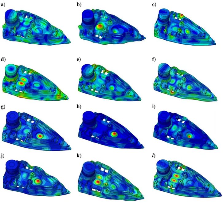
The natural frequencies and corresponding mode shapes for the final, optimized iron structure
were predicted. It should be stated that comparing the natural frequencies and modes shapes of the
older and the optimized structure revealed that both the natural frequencies and mode shapes were
quite different from each other. The mode shapes corresponding to natural frequencies within the
frequency range of interest (i.e., 35-40 kHz), presented in Fig. 6, suggested that the vibrations
within 35-40 kHz could be quite effective in the steam generating chamber, steam passageways, and
the rear chamber compared to the preliminary situation shown in Fig. 3. It is worth restating that
these locations are where lime particles are mostly seen to accumulate. The predicted mode shapes
in Fig. 6 also implied that a narrow band excitation could create effective vibrations at the desired
locations. For example, sweeping in a frequency range (e.g., 35-37 kHz) can provide effective
ultrasonic vibrations at all the desired regions in the iron. In an effort to verify the predictions, a test
rig was developed and ultrasonic vibration measurements on a prototype iron were carried out. The
Fig. 6. The vibration mode shapes predicted using the finite element model at frequency f being (a) 34.93 kHz, (b) 35.28 kHz, (c) 35.62 kHz, (d) 35.73 kHz, (e) 36.18 kHz, (f) 36.41 kHz, (g) 36.53 kHz, (h) 36.78 kHz, (i) 36.90 kHz, (j) 37.14 kHz, (k) 37.22 kHz and (l) 39.85 kHz. a) b) c) d) e) f) g) h) i) j) k) l)
3. Verification Using Operational Deflection Shapes
For the purpose of design verification, a prototype iron was built and forced vibrations of
this prototype at ultrasonic frequencies were measured using a laser vibrometer. Although the
bottom surface of the iron touches a surface when it is in use, the vibration tests were
performed in free-free conditions due to the advantages it offers when experimental and
theoretical results are to be compared [13]. This approach is justifiable, as the vibration
modes at ultrasonic frequencies are not expected to be significantly affected when the iron is
moved over a surface with a relatively very flexible foundation during the ironing operation.
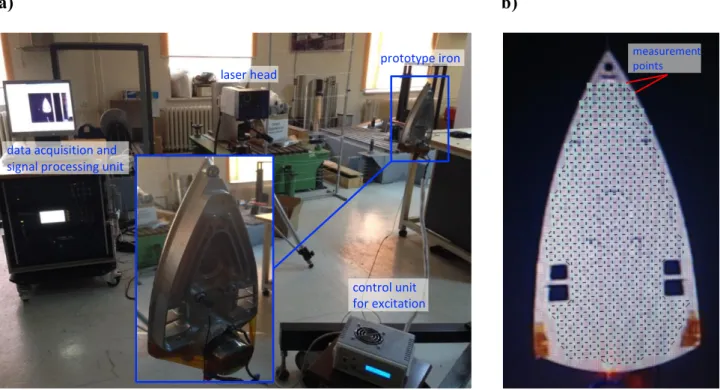
The excitation unit of the iron prototype was driven using a control unit and a scanning laser
vibrometer (PSV-400 Scanning Vibrometer, Polytec GmbH, Germany) was used to measure
the corresponding vibrations at 476 grid points on the back of the iron. The experimental
setup and the response locations are depicted in Fig. 7. The main purpose of these tests was to
excite the system at different frequencies and measure the responses at grid points in order to
determine the operational deflection shapes, expected to be similar to the mode shapes at or
around natural frequencies. The excitation frequency was varied from 35 to 40 kHz.
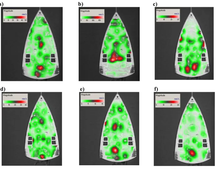
The measured operational deflection shapes are presented in Fig. 8. The results clearly indicated
that the ultrasonic exciter, specifically designed for this test, effectively excited the system and
a) b)
Fig. 7. (a) The experimental setup including the prototype steam iron with the excitation unit,
the control unit for excitation, the laser head, and the data acquisition/signal processing unit
of the laser vibrometer, and (b) the laser measurement points.
In order to verify finite element predictions, the measured operational deflection shapes were
visually compared to the predicted mode shapes. For example, the measured operational deflection
shape at 35 kHz in Fig. 8a is quite similar to the estimated mode shape at 35.3 kHz in Fig. 6b.
Similarly, the measured operational deflection shape at 36 kHz in Fig. 8b is very similar to the
estimated mode shape at 35.7 kHz in Fig. 6d. In general, the identified operational deflection shapes
indicate that the steam generating chamber, steam passageways and the iron bottom plate vibrate
effectively at ultrasonic frequencies as predicted by the numerical model. Finally, it should be noted
that this is not a finalized project yet. More research needs to be carried out before an ultrasonic
iron can become a reality. Although, the main body, i.e., base plate, of a steam iron is optimized for
effective ultrasonic vibrations and verified using a laser vibrometer here, the rest of the ultrasonic
prototype iron laser head
data acquisition and signal processing unit
control unit for excitation
measurement points
steam iron, including the electrical heating system, needs to be designed and manufactured for
physical tests.
a) b) c)
d) e) f)
Fig. 8. Vibration shapes at frequency f being (a) 35 kHz, (b) 36 kHz, (c) 37 kHz, (d) 38 kHz,
(e) 39 kHz and (f) 40 kHz, measured using a laser vibrometer.
4. Conclusions
This paper presents the results of research conducted towards the realisation of designing an
ultrasonic iron. After demonstrating experimental evidence that ultrasonic vibration in irons can
offer significant benefits towards minimising the accumulation of limescale, a methodology for
modelling, analysing and optimising an iron structure, so as to create effective vibrations within a
A piezoelectric-type ultrasonic exciter with a working frequency range of 35-40 kHz was
designed and optimized. A thermal isolator between the piezoelectric ceramics and iron surface was
used to avoid excessive heating of the piezoelectric ceramics. In addition, a conical-shaped part was
used to assemble the piezoelectric exciter with the ceramic isolator. Using finite element analyses,
the ultrasonic exciter was tuned so as to set its first natural frequency corresponding to the “tension-compression” mode to be close to the desired operational frequency. The iron structure was
optimized for effective ultrasonic vibrations at the operational frequency of the ultrasonic exciter.
An analytical investigation of a circular plate vibration was utilized during this optimization
process. Some stiffeners were also added to increase the stiffness of the shells on the iron body to
prevent local modes caused by local flexibilities in the iron. As one of the design variables, the
position of the ultrasonic exciter within the iron was also considered. After many simulations, a
feasible ultrasonic iron structure was designed. The predicted results for the optimized iron structure
indicated that the steam generating chamber, steam passageways, and the rear chamber did, in fact,
vibrate effectively at ultrasonic frequencies as we had intended.
For the purpose of design validation, a prototype iron was built, and forced vibrations of this
prototype at ultrasonic frequencies ranging from 35 to 40 kHz were measured using a laser
vibrometer. Measurement of the operational deflection shapes confirmed the expected behaviour of
the prototype. Furthermore, both predicted and measured vibration results suggested that an
ultrasonic excitation, with narrowband-sweeping frequency characteristics, could provide ultrasonic
vibrations at desired regions in an iron. The results of the theoretical and experimental vibration analyses as well as the physical experiments on steam irons in this study prove promising in
the design of ultrasonic irons, so as to minimize the accumulation of limescale. Furthermore,
we believe that ultrasonic vibrations can also improve performance by better smoothing
Acknowledgements
The authors would like to thank to Mr. Kerem Anbarcı, Mr. Hasan İbaçoğlu and Mr. Namık
Alpaydın from Aero Engineering Solutions Ltd. for their technical support. The authors also
thank Dr. Caroline Fell Kurban, Director of the Center for Excellence in Learning and
Teaching at MEF University for proofreading the final manuscript.
References
[1] M. Satake, Chemistry for Health Science, Discovery Publishing Pvt. Ltd, New Delhi, 2013. [2] D. Ensminger, L.J. Bond, Ultrasonics: Fundamentals, Technologies, and Applications, 3rd
ed., CRC Press, Boca Raton, FL, 2011.
[3] L. Panpan, Z. Chen, Experiment study on porous fiber drying enhancement with application of power ultrasound, Appl. Acoust. 127 (2017) 169–174. doi:10.1016/J.APACOUST.2017.06.003.
[4] M. Roopa Rani, R. Rudramoorthy, Computational modeling and experimental studies of the dynamic performance of ultrasonic horn profiles used in plastic welding, Ultrasonics. 53 (2013) 763–772. doi:10.1016/j.ultras.2012.11.003.
[5] D. Fernandez Rivas, B. Verhaagen, J.R.T. Seddon, A.G. Zijlstra, L.-M. Jiang, L.W.M. van der Sluis, M. Versluis, D. Lohse, H.J.G.E. Gardeniers, Localized removal of layers of metal, polymer, or biomaterial by ultrasound cavitation bubbles, Biomicrofluidics. 6 (2012) 34114. doi:10.1063/1.4747166.
[6] I.-C. Rosca, M.-I. Pop, N. Cretu, Experimental and numerical study on an ultrasonic horn with shape designed with an optimization algorithm, Appl. Acoust. 95 (2015) 60–69. doi:10.1016/j.apacoust.2015.02.009.
[7] G. Harvey, A. Gachagan, T. Mutasa, Review of high-power ultrasound-industrial applications and measurement methods, IEEE Trans Ultrason Ferroelectr Freq Control. 61 (2014) 481–495.
[8] H. Tan, G. Xu, T. Tao, X. Sun, W. Yao, Experimental investigation on the defrosting performance of a finned-tube evaporator using intermittent ultrasonic vibration, Appl. Energy. 158 (2015) 220–232. doi:https://doi.org/10.1016/j.apenergy.2015.08.072.
[9] M. Legay, B. Simony, P. Boldo, N. Gondrexon, S. Le Person, A. Bontemps, Improvement of heat transfer by means of ultrasound: Application to a double-tube heat exchanger, Ultrason. Sonochem. 19 (2012) 1194–1200. doi:https://doi.org/10.1016/j.ultsonch.2012.04.001.
[10] S. Jia, D. Zhang, Y. Xuan, L. Nastac, An experimental and modeling investigation of aluminum-based alloys and nanocomposites processed by ultrasonic cavitation processing, Appl. Acoust. 103 (2016) 226–231. doi:https://doi.org/10.1016/j.apacoust.2015.07.016. [11] B. Verhaagen, T. Zanderink, D.F. Rivas, Ultrasonic cleaning of 3D printed objects and
cleaning challenge devices, Appl. Acoust. 103 (2016) 172–181. doi:10.1016/J.APACOUST.2015.06.010.
[12] T. Kobayashi, T. Kobayashi, Y. Hosaka, N. Fujii, Ultrasound-enhanced membrane-cleaning processes applied water treatments: influence of sonic frequency on filtration treatments, Ultrasonics. 41 (2003) 185–190. doi:10.1016/S0041-624X(02)00462-6.
[13] F.J. Espinoza-Beltrán, K. Geng, J. Muñoz Saldaña, U. Rabe, S. Hirsekorn, W. Arnold, Simulation of vibrational resonances of stiff AFM cantilevers by finite element methods, New J. Phys. 11 (2009). doi:10.1088/1367-2630/11/8/083034.
advanced solutions answering to technology’s needs, Mech. Syst. Signal Process. 20 (2006) 1265–1285. doi:10.1016/j.ymssp.2005.11.015.
[15] K. Waldron, A. Ghoshal, M.J. Schulz, M.J. Sundaresan, F. Ferguson, P.F. Pai, J.H. Chung, Damage detection using finite element and laser operational deflection shapes, Finite Elem. Anal. Des. 38 (2002) 193–226. doi:10.1016/S0168-874X(01)00061-0.
[16] P. Vasiljev, S. Borodinas, R. Bareikis, A. Struckas, Ultrasonic system for solar panel cleaning, Sensors Actuators A Phys. 200 (2013) 74–78. doi:10.1016/j.sna.2013.01.009. [17] C. Yin, Z. Zhang, Z. Wang, H. Guo, Numerical simulation and experimental validation of
ultrasonic de-icing system for wind turbine blade, Appl. Acoust. 114 (2016) 19–26. doi:10.1016/J.APACOUST.2016.07.004.
[18] K.M. Liew, J.-B. Han, Z.M. Xiao, Vibration analysis of circular mindlin plates using the differential quadrature method, J. Sound Vib. 205 (1997) 617–630. doi:10.1006/jsvi.1997.1035.