PHOTONIC
CRYSTAL
BASED
MULTI-MODE
HIGH-Q
CAVITY
A.E. Akosman1,*, M. Mutlu1, H. Kurt2, E.Ozbay1
1Department of Electrical and Electronics Engineering, Nanotechnology Research Center, Bilkent University, 06800 Ankara, Turkey 2Department of Electrical and Electronics Engineering, TOBB University of Economics and Technology, 06580, Ankara, Turkey
Abstract— An optical race-track has been investigated in order to
obtain a multi resonant structure with high-Q factors. Photonic crystal based structure provides strong field confinement and scalability in the dimensions of the structure. The average value of the quality factors at the resonances have been calculated to be on the order of ~105.
Keywords-Photonic Crystal, Photonic Crystal Cavities, Optical Race Track
I. INTRODUCTION
Photonic crystal (PC) based cavities are formed by introducing a defect that is totally surrounded by periodically distributed dielectric or metallic particles. Cavity structures, which are used to confine light, have several photonic applications such as enhancing the active laser media [1], optical communication and optical data storage [2], increasing light-matter interactions [3]. The main focus of these applications is the confinement characteristics of the electromagnetic (EM) waves inside the cavity structure. Modal volume, V, and quality factor, Q, values are the parameters which are used to describe the confinement. In general, the desired designs exhibit small V and high Q values. In this study, the main concern is obtaining high Q values. The main aim of this work is to design a multi-mode, highly confined photonic structure, which cannot be realized easily using a classical PC based cavity configuration [4]. We show that the separation between the resonance frequencies can be controlled by modifying the length of the race-track. The advantage of the race-track structure is that the confined EM wave constitutes a standing wave pattern distributed along the race-track which itself is a PC waveguide ring. The PC waveguide provides stronger in-plane confinement compared to a bulk structure. The vertical confinement can be increased by adding extra layers at the top and the bottom of the dielectric rods to get total internal reflection at the vertical plane boundaries.
II. THEORETICAL ASPECT OF THE STUDY
PCs are usually periodically distributed dielectric structures which are utilized in order to control the propagation of the EM waves [4]. The photonic band gap (PBG) occurs for a specific range of frequencies at which EM wave propagation inside the PC is forbidden. However, a PC waveguide can be designed by removing one line of rods from the periodic structure. In this case, an EM wave penetrates along the waveguide with a strong confinement because of the band gap characteristics of
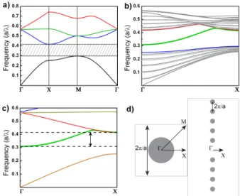
the PC structure. The frequency of the wave to be transmitted should lie inside the range of the PBG. The EM modes can be demonstrated using a dispersion diagram that represents the allowed modes corresponding to a certain frequency, ω and certain propagation constant, k. The detailed dispersion diagrams of the two dimensional PC and PC waveguide structure that has the same parameters with the race-track geometry are shown in Figure 1.
Fig. 1. a) The dispersion diagram of the two dimensional bulk PC consisting of rods with a radius of 0.22a, the shaded area represents the PBG. b) The dispersion diagram of a two dimensional PC waveguide. c) The combined dispersion relation of the bulk and waveguide structures. d) The representation of the propagation vectors and reciprocal spaces of the bulk and waveguide PC structures.
The range of frequencies allowed for transmission inside the waveguide lie within the region that is indicated in Fig. 1c. The PC waveguide structure provides confinement to the cavity modes. Moreover, the ring formed by the waveguide geometry creates Fabry-Perot type resonance inside the structure and that causes the EM waves to be standing waves. The frequency separation between the standing waves is given by the formula that is valid for a classical resonator [5];
νF = c/2d (1)
where c is the speed of light, d is the half path-length of the resonator. Using the value of the path-length, the frequency separation can be normalized as;
νFN = a/b (2)
where a is the periodicity of the PC and b is the total path length. Previously described concepts are examined in the study and the final design is constructed accordingly. The PC waveguide structure is responsible from the in-plane confinement and the race-track geometry creates standing waves with equal frequency separation.
III. THE RACE-TRACK GEOMETRY AND NUMERICAL RESULTS
The proposed structure is shown in Fig. 2, which contains electrically long (~15λ) dielectric rods with a relative permittivity of 9.61 and a radius of 0.22a, where a describes the periodicity of the square lattice PC structure.
Fig. 2. The two dimensional schematic of the PC race track geometry.
The structure has a waveguide path length of 68a that corresponds to a normalized frequency separation of 0.0147. The quality factors are estimated to be around ~105, considering the previous classical PC cavity structures [4].
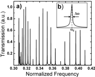
Fig. 3. a) The transmission spectrum inside the race track cavity. b) The enlarged view of a selected resonance peak.
The transmission spectrum of the cavity structure is numerically examined by placing two monopole antennas facing each other, at the positions indicated in Fig. 2. In the simulations, the frequency range is determined taking all the allowed waveguide modes into account, covering all of the
resonances inside the race track. The numerical analysis has been conducted using the Finite Difference Time Domain (FDTD) method. The total time in the simulations is set to be very long in order to be able to catch the high-Q resonances avoiding the loss of any frequency component. The FDTD result is given in Fig. 3.
The resonances are almost equally spaced on the frequency axis until 0.33 as shown in Fig. 3. It has been deduced that the equal spacing occurs only in the linear region of the waveguide band. The Q-factor values can be approximated by using two different methods. The first method makes use of the width of the resonance in the transmission results. The other solution uses the field decay of each resonance by applying an incident field that is narrower in the frequency domain. The first method is preferred to calculate the quality factor of each resonance, since the two methods give similar results. The formula that is used for calculating the value of the quality factor using the first method is given as [4],
Q = ωc /Δω (3)
where ωc is the center frequency of the resonance and Δω is
the full width at half maximum value of the transmission peak. After examining all the resonances, the average of the quality factors is obtained to be on the order of ~105.
IV. CONCLUSIONS
A PC based high-Q cavity structure is examined in the study. The advantages of the structure can be listed as the multi-mode resonances, the high-Q factors and the scalability of the structure. The race track geometry can be used to store optical data consisting of different frequencies (or bits) after further investigation. The structure can also be used in an active lasing media since the standing wave patterns encounters lower loss compared to a classical Fabry-Perot resonator.
The drawbacks of the structure, i.e. high out-of-plane and bending losses, can be suppressed using different mechanisms such as adding extra reflecting layers and changing the geometry of the bends inside the race track.
The comparison of the field-decay rates and transmission spectrum for quality factors, the effects and management of the out-of-plane losses will be investigated in a near-future work. Furthermore, the experimental demonstration of the proposed design will be investigated in a separate study.
REFERENCES
[1] O. Painter, R. K. Lee, A. Scherer, A. Yariv, J. D. Obrien , “Two-dimensional photonic band-gap defect mode laser”, Science ,vol. 284, pp. 1819-1821,1999.
[2] P. Michler, A. Kiraz, C. Becher, W. V. Schoenfeld, P. M. Petroff, Lidong Zhang, E. Hu, A. Imamoglu,”A quantum dot single-photon turnstile device.”, Science, vol. 290, pp. 2282-2285, 2000.
[3] K. J. Vahala, “Optical Microcavities”, Nature, vol. 424, pp. 839-846, 2003.
[4] J. D. Joannopoulos, R.D. Meade, J.N. Winn, “ Photonic Crytals: Molding Flow of the Light”, NJ: Princeton University Press, 2nd ed., 2008.
[5] B.E.A Saleh, M.C. Teich, “Fundamentals of Photonics”, 1st ed., NY: John Wiley & Sons, Inc., 1991.