THERMODYNAMIC ANALYSIS OF A NEW THE COMBINED POWER SYSTEM USING LNG'S COLD ENERGY
Dilek Nur ÖZEN
Department of Mechanical Engineering, Faculty of Engineeringand Architecture, Necmettin Erbakan University, Koycegiz Campus, 42140 Konya, TURKEY
(Geliş/Received: 05.05.2019; Kabul/Accepted in Revised Form: 16.07.2019)
ABSTRACT: In this study, a new combined power system was proposed for the Marmara Ereglisi receiver terminal and the power generation during the evaporation of liquefied natural gas (LNG) was investigated. The combined power system consists of an open Brayton cycle (BC), a closed Rankine cycle (HRC) operating at high temperatures, and a closed Rankine cycle (LRC) operating at low temperatures. In the combined power system, an optimum value for the LRC condenser inlet pressure was found to be 150.7 kPa. The total power consumed, including LNG pumps in the system was found to be 193.413 MW and 291.321MW net power produced from the system.
Key Words: LNG, Cold Energy, Brayton Cycle, ORC, Combined Power Cycles
LNG’nin Soğuk Enerjisini Kullanan Yeni Bir Birleşik Güç Sistemin Termodinamik Analizi
ÖZ: Bu çalışmada Marmara Ereğlisi alım terminali için yeni bir birleşik güç sistemi önerilmiştir ve sıvılaştırılmış doğalgazın (LNG) buharlaşması esnasındaki güç oluşumu araştırılmıştır. Birleşik güç sistemi bir açık Brayton çevrimi (BC), yüksek sıcaklıklarda çalışan bir kapalı Rankine çevrimi (HRC) ve düşük sıcaklıklarda çalışan bir kapalı Rankine çevriminden (LRC) oluşmaktadır. Bileşik güç sisteminde LRC kondenser giriş basıncı için optimum değer 150.7 kPa olarak bulunmuştur. Sistemdeki LNG pompaları da dahil harcanan toplam güç 193.413 MW ve sistemden üretilen net güç 291.321 MW olarak bulunmuştur.
Anahtar Kelimeler: LNG, Cold Energy, Brayton Cycle, ORC, Combined Power Cycles
INTRODUCTION
As energy consumption increases rapidly, energy resources are gradually decreasing. This situation makes saving measures and productivity applications compulsory in systems that produce or use energy. In recent years, work on power generation in LNG receiving terminals has been intensified. There are several studies in the literature which used the cold energy of LNG as heat sinks in combined power systems.
Yuanwei et al. (2011) have made the energy cycle based on the cold energy of liquefied natural gas analysis and optimization. They conducted a new analysis methodology that combines the energy level, and they determine the pinch analysis. Simulation results show that this new method of energy production was shown to be effective to improve the thermodynamic cycle. Shi and Chi (2009) have
worked in a combined power cycle that uses low-temperature waste heat and LNG cold energy. They proposed a combined power system in which low-temperature waste heat could be recovered efficiently and cold energy of liquefied natural gas (LNG) could also be fully utilized. The power output is equal to 1.25 MWh per kg ammonia-water mixture. For the operation of seawater pumps, approximately 0.2 MW of electrical power can be saved. Through simulation calculations, parametric analyzes are performed for the proposed combined cycle to evaluate the effects of key factors on the performance of the proposed combined cycle. The results show that as the inlet pressure of the ammonia turbine increases and the ammonia mass ratio increases, the maximum net electrical efficiency can be achieved when the peak value increases. Ghaebi et al. (2017) carried out energy, exergy and economic analysis of a new ammonia-water combined cooling and power cycle using waste heat as a low temperature heat source and LNG cold energy as thermal sink. They observed that higher ammonia concentrations could achieve a higher first law efficiency at heat source temperatures and at LNG turbine inlet pressures or at lower condenser temperatures and steam generator pressures, and could achieve a higher efficiency in lower ammonia concentrations, heat source temperatures and condenser temperatures at higher steam generator pressures, evaporator temperatures and LNG turbine inlet pressures. Behar et al. (2013) stated that LNG uses solar energy to increase the performance of the hybrid gas turbine. Compared to the non-cooled hybrid plant, the LNG cooling system increases the output of the solar gas turbine by 5% while increasing efficiency by 1%. Ersoy and Demirpolat (2016) investigated open and combined Rankine cycle power generation during evaporation of liquefied natural gas at Marmara Ereglisi receiver terminal. For the combined Rankine cycle, they determined that the power required for LNG pumps used in the terminal could be met and beyond that, an additional 6.57 MW could be generated. Tan et al. (2016) conducted an experimental study on self-cooling automatic air conditioning system based on LNG fuel trucks. They indicate that the self-cooling air conditioning system for LNG fueled trucks is feasible and that the cooling capacity storage methods should be used to adjust the cold supply due to the fluctuation of LNG consumption rate and the mismatch of the demand. Bao et al. (2017) presented the effects of progressive condensation on power generation systems for LNG cold energy recovery. When the net power output was objective, the net power output of the three-stage combined cycle was the largest. Kanbur et al. (2017) has made thermo-economic and environmental assessments of a combined cycle for the use of small-scale LNG cold. They found that the single system has a 25% lower level of product cost than the combined system at the actual pressure ratio. A simple graphical based thermoeconomic optimization study shows that the minimum relative cost differences are in different locations for the combined cycle. Franco and Casarosa (2015) carried out the thermodynamic analysis of direct expansion configurations for electricity generation with LNG cold energy recovery. Using a direct expansion configuration with a multi-stage turbine, in which they apply a simplified thermodynamic model, it shows that the energy production values typical for optimized ORC plant configurations (120 kJ per kg of natural gas flowing through the plant) can be obtained. The development of a direct expansion plant with a multi-stage turbine and an internal heat recovery system can allow for closer to 160 kJ of production for each kg of flowing liquefied natural gas. Considering the mass flow rate values typical of LNG gas stations (eg 70 kg / h); this corresponds to an output power of 8.3 MW to 11.4 MW.
Turkey are among the countries that imported LNG. Turkey, which supplies natural gas needs from foreign markets, LNG is observed that its importance increases with each passing day. Its two gasification LNG receiving terminal that has been raised in Turkey's recent investment in a new terminal. The increasing use of LNG makes it important for our country to work on saving and recovering the cold energy of LNG. In this study, a combined power system for a LNG receiving terminal in Turkey are proposed. The purpose of a combined power system is to utilize the cold energy of liquefied natural gas. The proposed power system contributes both to energy saving and to the environment. The combined power system consists of open Brayton cycle, two closed Rankine cycles.
Description of The Proposed Combined Power System That Use LNG Cold Energy
The combined power cycle consists of the open Brayton cycle and two closed Rankine cycles (RC) operating at low (LRC) and high (HRC) temperatures.Rankine cycle operating at low temperature uses Rankine cycle which operates at high temperature as heat source. The schematic diagram of the system is shown in Fig. 1.
Figure 1. Schematic diagram of the combined power system.
Liquefied natural gas is gasified through the condenser of the LRC using R718 (water) as working fluid. The natural gas then enters the combustion chamber in the Brayton cycle. The exhaust gases from the combustion chamber are used as a heat source for the HRC. The heat taken from the condenser in the HRC is taken by the evaporator element of the LRC and the cold energy of the liquefied natural gas is used for the removal of this heat from the system. This combined power cycle aims to:
• Utilizing the cold energy of liquefied natural gas
• Waste heat utilization by exhaust gas in the Brayton cycle • Heat utilization from the condenser in the closed Rankine cycle Mathematical Model of the Combined Power System
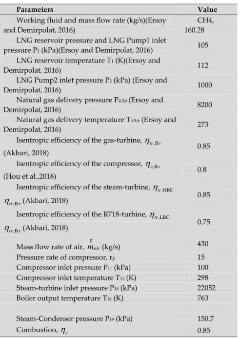
A combined power system was designed using the parameters of the Marmara receiving terminal. The main parameters for this power system are given in Table 1. Pinch point temperature for the condenser component are assumed to be 10 in the system. Compressor pressure ratio is assumed to be 15. The low pinch point temperature increases the efficiency of the heat exchanger. High compressor pressure ratio in Brayton cycle increases power generation. These values, which affect the performance of the system positively, are kept constant and the condenser inlet pressure of HRC is accepted the decision variable. The effect of condenser inlet pressure on the performance of the system was investigated. In particular, the examination of this parameter affects the heat transfer from the condenser in the HRC to the evaporator in the LRC. Because the condenser pressure affects the temperature in the condenser. The condenser inlet pressure at HRC affects power generation at both HRC and LRC. A mathematical model has been developed for thermodynamic analysis. Mathematical model was established with EES program. Each component is modeled considering mass and energy balances.
Table 1. Main parameters for the calculations
The following assumptions are made for the combined power system analysis:
The flow is considered to be a steady-state. At no point in the system it is assumed that properties of the flow have not changed over time
The pressure and heat losses in the system components are ignored. LNG is considered to be pure methane (Ersoy and Demirpolat , 2016) All components are insulated.
It has been accepted that the Brayton cycle is performed with 50% excess air. LNG Reservoir and LRC
In the LNG receiving terminals, heat transfer is required with a high temperature heat source to convert liquefied natural gas into natural gas. Similarly, in a combined power cycle, heat transfer is required with a low temperature heat source to condense the circulating steam and to cool the cycle
Parameters Value
Working fluid and mass flow rate (kg/s)(Ersoy and Demirpolat, 2016)
CH4, 160.28 LNG reservoir pressure and LNG Pump1 inlet
pressure P1 (kPa)(Ersoy and Demirpolat, 2016) 105 LNG reservoir temperature T1 (K)(Ersoy and
Demirpolat, 2016) 112
LNG Pump2 inlet pressure P2 (kPa) (Ersoy and
Demirpolat, 2016) 1000
Natural gas delivery pressure P4,5,6 (Ersoy and
Demirpolat, 2016) 8200
Natural gas delivery temperature T4,5,6 (Ersoy and
Demirpolat, 2016) 273
Isentropic efficiency of the gas-turbine,
tr,Br(Akbari, 2018) 0.85
Isentropic efficiency of the compressor,
c,B r(Hou et al.,2018) 0.8
Isentropic efficiency of the steam-turbine,
tr,HRC,B tr r
(Akbari, 2018) 0.85Isentropic efficiency of the R718-turbine,
tr,LRC,B tr r
(Akbari, 2018) 0.75Mass flow rate of air,
m
air g(kg/s) 430
Pressure rate of compressor, rp 15
Compressor inlet pressure P11 (kPa) 100 Compressor inlet temperature T11 (K) 298 Steam-turbine inlet pressure P18 (kPa) 22052
Boiler output temperature T18 (K) 763
Steam-Condenser pressure P19 (kPa) 150.7
members. The condensation of the vapor in the proposed combined power system and the conversion of the liquefied natural gas to natural gas will be carried out by the LRC.
The pressure of the LNG at a low temperature of -161oC taken from the storage tank is increased by the two LNG pumps. The pressure of the LNG leaving the second pump (P2) corresponds to the pressure
of the natural gas in the consumer line. The required pump works are given in the following equations.
, 1
.(
2 1)
LNG P LNGW
m
h
h
(1) , 2.(
3 2)
LNG P LNGW
m
h
h
(2) where 2 1 LNG P, 1h
h
w
(3) where , 1 1.(P
2P )
1 LNG Pw
v
(4) where 3 2 LNG P, 2h
h
w
(5) where , 2 2.(P
3P )
2 LNG Pw
v
(6)The pressurized LNG is converted to the gas phase by taking heat from the condenser in the LRC. The condenser heat (
Q
3,4 ) is given by 4 3 3,4 LNG
.(
)
Q
m
h
h
(7)The pump and turbine powers in the LRC are calculated by the following equations respectively.
p,LRC LRC
.(
9 8)
W
m
h
h
(8) tr,LRC LRC.(
10 7)
W
m
h
h
(9) where 7 10 tr,LRC.(h
10 7s)
h
h
h
(10) 3,4 7 8(
)
LRCQ
m
h
h
(11) 9 10 19,20 LRCQ
h
h
m
(12) The heat (Q
18,19 ) from the condenser of the closed Rankine cycle passes to the evaporator of the LRC. This heat is found by the following equation.
,LRC p,LRC
19,20 tr 3,4
Q
W
Q
W
(13)Open Brayton Cycle
In this cycle, the ambient air compressor enters and pressurizes. The pressurized air enters the combustion chamber; the air is heated by the combustion of the fuel. The pressurized and heated air is energized and extended across the turbine and work is obtained. The turbine and compressor power in the Brayton cycle is given by the following equations respectively.
12 11
.(
)
comp airW
m
h
h
(14) tr,gas T.(
13 14)
W
m
h
h
(15) where 12 11 12 11 c,B(h
s)
rh
h
h
(16) 14 13 tr,Br.(h
13 14s)
h
h
h
(17) Tm
is the total mass of combustion products and is given by the following equation.
T air fuel
m
m
m
(18)The fuel in the combustion chamber is assumed to burn with 50% excess air. According to this, the amount of fuel (
m
fuel
) is found by combustion reaction of methane gas.
4
3(O
23.76 N )
20.8
20.2
2
21.1
211.28
2CH
CO
CO
H O
O
N
(19)The heat value of the fuel is found by the following equation.
4 4 4 4 2 2 2 2 2 2 2 2 2 2 2 2 2 2 2 2 2 2 2 2 0 0 0 0 0 0 0 0
(h
h
h
) 3
(h
h
) 11.28
(h
h
)
0.8
(h
h
h
) 2
(h
h
h
) 11.28
(h
h
)
0.2
(h
h
h
) 1.1
(h
h
)
CH fCH CH CH O O O N N N c CO fCO CO CO H O fH O H O H O N N N CO fCO CO CO O O OQ
nM
nM
nM
nM
nM
nM
nM
nM
(20)The heat received (
Q
cc
) by the combustion products is found by the following equation. The combustion efficiency was considered as 90%.
.
c cc cQ
Q
(21)High Temperature Closed Rankine Cycle
In the Brayton cycle, the heat of the exhaust gases from the turbine was used as heat source for the Rankine cycle. The pump and turbine powers in the Rankine cycle are given by the following equations respectively. p,HRC HRC
.(
17 20)
W
m
h
h
(22) tr,HRC HRC.(
18 19)
W
m
h
h
(23) where 17 20 p,HRCh
h
w
(24) where p,HRC 20.(P
20P )
17w
v
(25) 19 18 tr,HRC.(h
18 19s)
h
h
h
(26) 19,20 19 20(
)
HRCQ
m
h
h
(27)The efficiency of the combined power system
The net power and efficiency obtained from the combined power system are given by the following equations respectively. ,HRC ,LRC ,Br LNG,P1 LNG,P 2 p,LRC p,HRC
(
)
net tr tr tr compW
W
W
W
W
W
W
W
W
(28)100
net cycle ccW
Q
(29)RESULTS AND DISCUSSION
The performance of the above-mentioned combined power system under the optimum operating condition is summarized in Table 2.
Table 2. Calculation results for the combined power cycle.
tr,gas
W
(kW) tr,HRCW
(kW) tr,LRCW
(kW) compW
(kW) pump,totalW
(kW) netW
(kW) cycle
% 415687 45863 23184 189948 3465 291321 46.1 05In the LRC, R718 was selected as the working fluid in particular. Because R718 absorbs a considerably larger amount of energy in the form of heat during a phase change of the liquid without changing the temperature. The high latent heat of evaporation of the R718 refrigerant ensures high heat at low temperatures and mass flow.
Due to this feature of the R718 refrigerant, it is aimed to increase the heat source of the LRC by increasing the condenser pressure in the closed Rankine cycle.
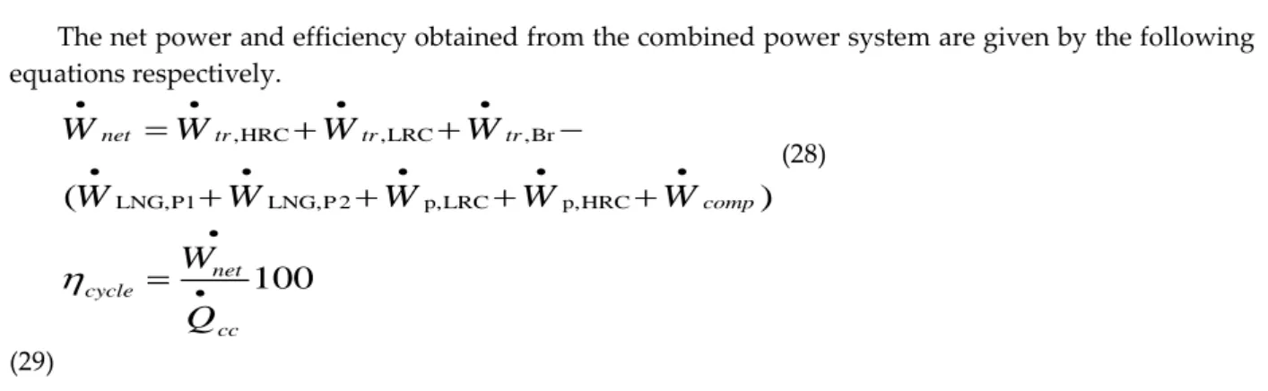
As expected in the HRC cycle, increasing the condenser pressure reduced the turbine power obtained from this cycle as the turbine pressure difference decreased, as shown in Fig.2. Turbine power was increased in this cycle because increasing the condenser pressure provided a higher heat source for the LRC (Fig. 3).
Figure 2. Effects of Rankine cycle-condenser pressure in combined power system on HRC turbine power and thermal efficiency
Figure 3. Effects of Rankine cycle-condenser pressure in combined power system on steam-turbine power and R718-turbine power
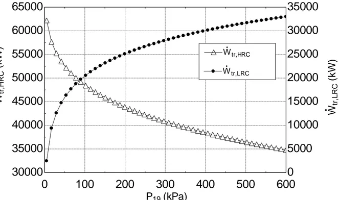
As shown in Fig.4, the efficiency of the cycle increased initially and then began to decrease. This is due to the fact that the efficiency of the system has increased since the power increase of the turbine in the LRC cycle was more than the power decrease of the turbine in the HRC cycle. After a certain point, the power reduction of the turbine in the HRC cycle begins to overcome the power increase of the turbine in the LRC cycle. This has led to a reduction in net power in the system and thus a decrease in the efficiency of the system (Fig.5).The increase in condenser pressure has also increased the steam quality in the last stages of the turbine. This will cause the liquid particles in the vapor to decrease and
0
100
200
300
400
500
600
30000
35000
40000
45000
50000
55000
60000
65000
45.4
45.5
45.6
45.7
45.8
45.9
46
46.1
46.2
P
19(kPa)
W
tr ,H R C(
k
W
)
W
tr,HRCh
cyc le(
%
)
h
cycleh
cycle0
100
200
300
400
500
600
30000
35000
40000
45000
50000
55000
60000
65000
0
5000
10000
15000
20000
25000
30000
35000
P
19(kPa)
W
tr,HRCW
tr ,L R C(
k
W
)
W
tr,LRCW
tr,LRCW
tr ,H R C(
k
W
)
thus increase the turbine efficiency and lifetime. As the condenser pressure increases, the efficiency of the combined power system increases at the beginning and then decreases. The cycling efficiency starts to decrease after the 150.7 kPa condenser pressure value. Therefore, this value is the optimum condenser pressure value in closed Rankine cycle.
Figure 4. Effects of Rankine cycle-condenser pressure in combined power system on R718-turbine power and thermal efficiency
Figure 5. Effects of Rankine cycle-condenser pressure in combined power system on net power and thermal efficiency
0
100
200
300
400
500
600
0
5000
10000
15000
20000
25000
30000
35000
45.4
45.5
45.6
45.7
45.8
45.9
46
46.1
46.2
P
19(kPa)
W
tr,LRCh
cyc le(
%
)
h
cycleh
cycleW
tr ,L R C(
k
W
)
0
100
200
300
400
500
600
286000
287000
288000
289000
290000
291000
292000
45.4
45.5
45.6
45.7
45.8
45.9
46
46.1
46.2
P
19(kPa)
W
n e t(
k
W
)
W
neth
c y c le(
%
)
h
cycleh
cycleIn Fig. 6 only the efficiency of the system with BC (ηBr), BC and HRC with the efficiency of the system (ηBr,HRC) and BC, HRC and LRC with the efficiency of the combined system (ηcycle) is shown. The addition of HRC and LRC cycles to the Brayton cycle increased the efficiency of the system by 34%.The efficiency evaluation is made specifically for the Brayton cycle because the heat source of the combined power system is obtained from the combustion chamber of this cycle.
Figure 6. The thermal efficiencies of the cycles in the combined power system
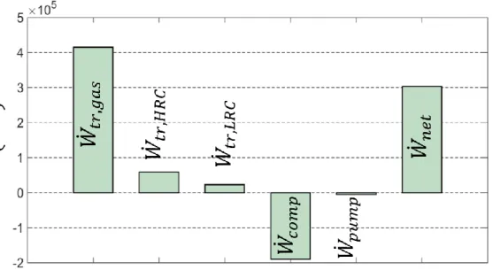
Figure 7. The powers of the cycles in the combined power system
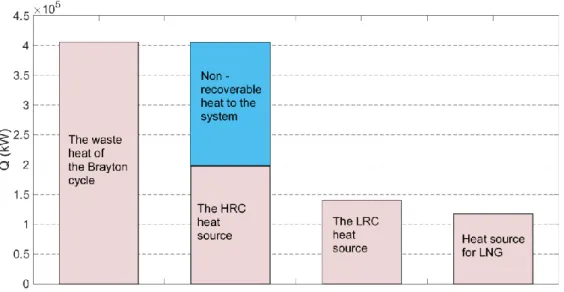
Figure 8. The heat source and waste heat of the cycles in the combined power system
Fig.7 shows the turbine powers of BC, HRC and LRC cycles ( , , ), the compressor
and pump power ( , ) used in the system and the net power ( ) obtained from the system.
As shown in Fig.7, the maximum power from the composite system was obtained from the BC cycle and then from the HRC and LRC cycles, respectively. The power required for LNG pumps can be provided by using 13% of the power obtained by using only the LRC.
The heat drawn from the Brayton cycle is 406.130 MW. By adding the HRC, the heat from the cycle was 140.621 MW. With the addition of the LRC this value has decreased to 117.438 MW. As shown in Fig. 8, waste heat is utilized by the cycle integration and the amount of heat exhausted from the system is reduced. As a result, some of the waste heat of the Brayton cycle is recycled to the system. This value is 198.061 MW. Because, in the LRC, the heat taken from the condenser turns the LNG into the gas phase and this energy is also utilized.
CONCLUSION
This paper is investigated the applicability of the combined power system for a LNG receiving terminal in Turkey. With the proposed combined power system, it is aimed to utilize the cold energy of LNG and waste heat from low temperature. A mathematical model was developed for the combined power system and calculations were made in the EES computer program. The following results were obtained in the study.
The net power obtained from the combined power system is 291.321MW and the efficiency of cycle is 46.105%
There is an optimum point in the condenser pressure in the closed Rankine cycle for the combined power system. This value is 150.7 kPa, and after this value increase of the pressure decreases the efficiency of the cycle.
The power required for LNG pumps is 13% of the power obtained from only the LRC. NOMENCLATURE
h specific enthalpy (kJ/kg)
formation specific enthalpy (kJ/kmol) HRC high temperature Rankine cycle mass flow rate (kg/s)
n mole (kmol)
rp pressure ratio
heat transfer rate (kW) T temperature (K)
produced or consumed power by components (kW) Greek letters
efficiency
combustion efficiency Subscripts
Br Brayton cycle
c,Br compressor of Brayton cycle comp compressor
F fuel p pump P product tur turbine
tr,Br turbine of Brayton cycle tr,LRC turbine of LRC tr,HRC turbine of HRC REFERENCES
Akbari, N., 2018, Introducing and 3E (energy, exergy, economic) analysis of an integrated transcritical CO2 Rankine cycle, Stirling power cycle and LNG regasification process. Applied Thermal Engineering, 140, 442-454.
Bao, J., Lin, Y., Zhang, R., Zhang, N., & He, G., 2017, Effects of stage number of condensing process on the power generation systems for LNG cold energy recovery, Applied Thermal Engineering, 126, 566-582.
Badami, M., Bruno, J. C., Coronas, A., & Fambri, G., 2018, Analysis of different combined cycles and working fluids for LNG exergy recovery during regasification. Energy, 159, 373-384.
Behar, O., Khellaf, A., Mohammedi, K., & Ait–Kaci, S. Enhancing the performance of solar hybrid gas turbine using LNG cold energy.
Cao, Y., Rattner, A. S., & Dai, Y., 2018, Thermo economic analysis of a gas turbine and cascaded CO2 combined cycle using thermal oil as an intermediate heat-transfer fluid. Energy, 162, 1253-1268.
Choi I-H, et al., 2013, Analysis and optimization of cascade Rankine cycle for liquefied natural gas cold energy recovery. Energy, 61:179–95.
Ersoy, H. K., & Demirpolat, S. O., 2009, Using liquefied natural gas cold energy for power generation: case study for Marmara Ereglisi receiving terminal, Journal of the Energy Institute, 82(1), 11-18. Ghaebi, H., Parikhani, T., & Rostamzadeh, H., 2017, Energy, exergy and thermo economic analysis of a novel combined cooling and power system using low-temperature heat source and LNG cold energy recovery, Energy Conversion and Management, 150, 678-692.
Gómez, M. R., Garcia, R. F., Carril, J. C., & Gómez, J. R., 2014, High efficiency power plant with liquefied natural gas cold energy utilization. Journal of the Energy Institute, 87(1), 59-68.
Hou, S., Zhou, Y., Yu, L., Zhang, F., & Cao, S., 2018, Optimization of the combined supercritical CO2 cycle and organic Rankine cycle using zeotropic mixtures for gas turbine waste heat recovery. Energy conversion and management, 160, 313-325.
Kanbur, B. B., Xiang, L., Dubey, S., Choo, F. H., & Duan, F., 2017, Thermo economic and environmental assessments of a combined cycle for the small scale LNG cold utilization, Applied Energy, 204, 1148-1162.
Khaljani, M., Saray, R. K., & Bahlouli, K., 2015, Comprehensive analysis of energy, exergy and exergo-economic of cogeneration of heat and power in a combined gas turbine and organic Rankine cycle. Energy Conversion and Management, 97, 154-165.
Kim KH, Kim KC., 2014, Thermodynamic performance analysis of a combined power cycle using low grade heat source and LNG cold energy. Appl Therm Eng, 70:50–60.
Lee S., 2017, Multi-parameter optimization of cold energy recovery in cascade Rankine cycle for LNG regasification using genetic algorithm. Energy, 118:776–82.
Li P, et al., 2016, A cascade organic Rankine cycle power generation system using hybrid solar energy and liquefied natural gas. Sol Energy, 127:136–46.
Lu T, Wang K., 2009, Analysis and optimization of a cascading power cycle with liquefied natural gas (LNG) cold energy recovery. Appl Therm Eng, 29(8):1478–84.
Mosaffa A, Mokarram NH, Farshi LG., 2017, Thermo-economic analysis of combined different ORCs geothermal power plants and LNG cold energy. Geothermics, 65:113–25.
Nami, H., Mahmoudi, S. M. S., & Nemati, A., 2017, Exergy, economic and environmental impact assessment and optimization of a novel cogeneration system including a gas turbine, a supercritical CO2 and an organic Rankine cycle (GT-HRSG/SCO2). Applied Thermal Engineering; 110, 1315-1330.
Shi, X., & Che, D., 2009, A combined power cycle utilizing low-temperature waste heat and LNG cold energy. Energy conversion and management, 50(3), 567-575.
Song Y, et al., 2012, Thermodynamic analysis of a transcritical CO 2 power cycle driven by solar energy with liquified natural gas as its heat sink. Appl Energy, 92:194–203.
Tan, H., Sun, N., Lin, C., & Li, Y., 2016, Experimental study on a self-refrigerated auto air conditioning system based on LNG-fuelled trucks, In Industrial Electronics and Applications (ICIEA), 2016 IEEE 11th Conference on (pp. 1586-1591). IEEE.
Wang H, Shi X, Che D., 2013, Thermodynamic optimization of the operating parameters for a combined power cycle utilizing low-temperature waste heat and LNG cold energy. Appl Therm Eng, 59:490–7.
Yuanwei, L., Hongchang, Y., & Chongfang, M., 2011, Analysis and optimization of the power cycle based on the cold energy of liquefied natural gas. In Measuring Technology and Mechatronics Automation (ICMTMA), 2011 Third International Conference on (Vol. 1, pp. 455-458). IEEE.
Zhang G, Xu W, Yang Y, Zhang D., 2014, Utilization of LNG cryogenic energy in a proposed method for inlet air cooling to improve the performance of a combined cycle. Energy Proc, 61:2109–13.
Zhang G, Zheng J, Yang Y, Liu W., 2016, A novel LNG cryogenic energy utilization method for inlet air cooling to improve the performance of combined cycle. Appl Energy,179:638–49.
Zhao P, Wang JF, Dai Y, Gao L., 2015, Thermodynamic analysis of a hybrid energy system based on CAES system and CO2 transcritical power cycle with LNG cold energy utilization. Appl Therm Eng, 91:718–30.