152 IEEE TRANSACTIONS ON ANTENNAS AND PROPAGATION, VOL. 44, NO. 2, FEBRUARY 1996
arative
Evaluation of Absorbing
ary Conditions Using Green’s
ctions for Layered Media
M. I. Aksun, Member, IEEE, and Gulbin Dural, Member, IEEEAbstract- Absorbing boundary conditions are comparativdy studied using the Green’s functions of the vector and scalar potentials for multilayer geometries and general sources. Since the absorbing boundaries are introduced as additional layers with predefined reflection coefficients into the calculation of the Green’s functions, this approach provides an absolute measure of the effectiveness of different absorbing boundaries. The Green’s functions are calculated using different reflection coefficients corresponding to different absorbing boundaries and compared to those obtained with no absorbing boundary. It is observed that the perfectly matched layer (PML) is by far the best among the other absorbing boundary conditions whose reflection coefficients are available.
I. INTRODUCTION
PPLICATION of the numerical techniques based on differential equations in unbounded regions, such as the finite-difference time-domain (FDTD) and the finite-element methods (FEM), requires the truncation of the solution do- main with artificial boundaries. Ideally, these boundaries are supposed to absorb all the incident waves, that is, there should be no reflected waves, so they are called absorbing or radiation boundaries [1]-[7]. However, there is always some reflected waves due to imperfect cancelation of the impinging waves on these artificial boundaries. The level of the reflection depends upon the absorbing boundaries used and the order of the approximation.
Since different absorbing boundaries give rise to differ- ent level of reflected waves, one needs to examine these boundary conditions comparatively to decide on the type and the order of the absorbing boundary condition (ABC) to be used, to improve the accuracy of results. For the purpose of comparison, numerical experiments can be performed [SI, [9] on the geometry of interest, but here, we propose the use of Green’s functions to assess the level of imperfections of the ABC’s for planar geometries. The Green’s functions used in the comparative evaluation of ABC’s are provided for general sources and planar stratified media by including the reflections from each boundary [ 101. The absorbing boundaries are considered as additional layers, for which the reflection coefficients can be derived explicitly, above the original struc-
Manuscript received August 5, 1994; revised May 11, 1995.
M. I. Aksun is with the Department of Electrical and Electronics Engineer- G. Dural is with the Department of Electrical and Electronics Engineering, Publisher Item Identifier S 0018-926X(96)01195-7.
ing, Bilkent University, 06533 Ankara, Turkey. Middle East Technical University, 06531 Ankara, Turkey.
ture forming a multilayer geometry. The Green’s functions of the vector and scalar potentials are then calculated and compared with those obtained for the original geometry (no absorbing boundary) to observe the effect of the ABC’s on the Green’s functions, providing an absolute measure of merit of the ABC’s. The Green’s functions used in this approach are calculated in the spatial domain via either numerically integrating the Sommerfeld-type integrals or approximating the integrals in closed form [ 101. The technique proposed here eliminates extraneous problems caused by the discretizations required by the techniques used in conjunction with the ABC’s and, therefore, gives a true comparison of different types and orders of the ABC’s.
In this paper, the Green’s function-based comparison of the ABC’s is given for the sources of a horizontal electric dipole and a horizontal magnetic dipole in multilayer media. The comparison is based on the absorbing boundaries formulated by [3] for normal incidence, by [4], [5] for arbitrary angle of incidence, and by Berenger [ 111 as the perfectly matched layer (PML). The main goal of this approach is to compare the ABC’s for planar geometries for the purpose of finding an
ABC that can be used accurately. Even though the conclusion
drawn here may not be directly extended to other geometries (nonplanar), the technique can be applied to any geometry provided that corresponding Green’s functions are available.
The Green’s functions used in the evduation of the ABC’s are discussed in Section 11, including how these Green’s functions in the spatial domain are obtained and how the absorbing boundaries are accounted for in the calculation. The reflection coefficients for the absorbing boundaries studied in this paper are presented in Section 111, and discussion on the numerical results is given in Section IV.
U. GREEN’S FUNCTIONS FOR MULTILAYER MEDIA The Green’s functions of the vector and scalar potentials used for the evaluation of the ABC’s are given in [lo] for the multilayer geometry, shown in Fig. 1, and for the sources of horizontal electric dipole (HED), horizontal magnetic dipole (HMD), vertical electric dipole (VED), and vertical magnetic dipole (VMD). Therefore, only a brief outline of the formu- lation is provided here, and, in addition, the spectral-domain Green’s functions of HED and HMD, which are used in the applications presented in this paper, are given in the Appendix.
AKSUN AND DlJRAL: COMPARATIVE EVALUATION OF ABSORBING BOUNDARY CONDITIONS 153 region -(i+m) region -(ii+l) Z=Z ,-h z=d i-h source region-(i-m) Z=-Z -m -h
Fig. 1. General multilayer geometry.
The multilayer geometry used in the formulation of the Green’s functions (Fig. 1) consists of arbitrary number of planar layers with different electric and magnetic properties
( e r n , p T % ) and thicknesses (&). The perfect electric and mag- netic conducting planes (PEC and PMC) and half-space are also considered as layers for the formulation. The Green’s functions are first obtained in the spectral domain, as given in the Appendix, including the reflections from each boundary, then the spatial-domain Green’s functions are calculated either with the numerical evaluation of Sommerfeld’s integral [ 11 (exact) or in closed forms (approximate) using the generalized pencil of functions (GPOF) method [lo], [13]. Both exact and approximate forms of the Green’s functions are used for the purpose of comparison, but the numerical evaluation of the Sommerfeld integral is prefered for the results presented here, in this paper, to eliminate any question regarding to the possibility of error in the approximation. The numerical evaluation of the Sommerfeld integral is performed with the method of averages [14], which is considered to be the fastest algorithm available.
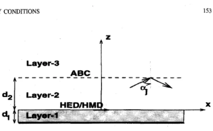
These Green’s functions can be utilized in the comparative evaluation of the ABC’s by introducing the absorbing bound- ary as an additional layer above the original structure (Fig. 2), forming a multilayer geometry. Since the reflection coefficients associated with different ABC’ s are available, the Green’s functions for the geometry with an absorbing boundary can be obtained by including the reflection coefficients of the ABC’ s in the formulation. To examine the effect of ABC’s, these Green’s functions are compared with the Green’s functions obtained for the ideal case which corresponds to the original geometry with no absorbing boundary.
111. ABSORBING BOUNDARIES
Various absorbing boundaries have been developed for the purpose of :simulating an unbounded region for the solution of differential-equation-based numerical techniques. These ab- sorbing boundaries can be formed as mode annihilating opera- tors, one-way wave equations, numerical approximations, and perfectly matched layers. Although the recent trend was toward
X
Fig. 2. A typical planar geometry
numerical simulations of the absorbing boundaries, with the recent introduction of a novel boundary condition by Berenger, PML [ 11 ], this approach has gained a flurry of interest. It was numerically demonstrated that the PML absorbing boundary is more accurate than the second-order Mur [3] for 2-D and 3-D geometries [9]. In this paper, the PML absorbing boundary is compared to the other absorbing boundaries given by [3]-[7] for planar geometries. Since comparison given in this paper is based on the Green’s functions it has the advantage of being immune to the error introduced by the numerical techniques due to discretizations.
The analytical absorbing boundary conditions discussed in this study are based on one-way wave equations and the corresponding reflection coefficients can be obtained as described in [ 3 ] , [6]. Expressions for the reflection coefficients are given here for the second- and third-order ABC’s as
-2
+PO + P 2 32
+PO + P 2 8qo?
+ay
+ P O +Pa%R = (second order) (1)
k z k le2 k 2
- 4 o c - 4 2 - +PO +Pa$
R = 2 2 (third order) ( 2 )
where the subscript i stands for the layer number, k , is the wave number in the transverse direction, and p’s and q’s depend upon the type of the approximation used in the derivation of the ABC and are given in [6]. A more general
absorbing boundary, which is designed to absorb the plane waves incident at arbitrary angles, can be represented by the following reflection coefficient [4], [ 5 ]
cosa3 -
5L
3=1 cosaj+
2
order k , k R = - ( 3 )where the perfect absorption occurs at the angles of aj’s.
The PML absorbing boundary is based on the absorption of electromagnetic waves by creating a nonphysical absorbing layer, or perfectly matched layer, that has a wave impedance independent of the angle of incidence and frequency [ll]. The PML absorbing boundary consists of a normal free- space computational zone and a PML outer boundary layer backed by a perfectly conducting (PEC) wall. In this approach it is suggested that the loss associated with PML should increase gradually with depth, p, within the layer as a ( 6 ) =
154 IEEE TRANSACTIONS ON ANTENNAS AND PROPAGATION, VOL. 44, NO. 2, FEBRUARY 1996
-
WfoABC wf ABC (PML)wf ABC (2nd order Pade) wf ABC (3rd order Pade) w l ABC (2nd order [ 4 ] ) _ _ _ _ . -8.0
_ _ _
-18.0'
' ' ' ' -3.0 -2.0 -1.0 0.0 1.0 2.0 Fig. 3. an HED. Layer-1:cm; layer-3: absorbing boundary, f = 1.0 GHz.
Magnitude of the Green's function of the vector potential, G& for
= 4.0, d l = 0.02032 cm; layer-2: air, dz = 10.0
amax(p/S)n. Hence, it yields a PML reflection factor of (4) where
S
is the PML thickness, 0 is the loss associated withthe layer, and c is the velocity of light. With the proper choice of
6,
0, and n, the reflection coefficient as low as 1/3000th those of standard second- and third-order ABC's, such as [3], has been reported [ 1 11.R ( Q ) = e-2u,,x6 cos Q / ( n + l ) t o c
IV. RESULTS AND DISCUSSION
The approach discussed in Section I1 can be applied to any multilayer geometry with arbitrary layer parameters, such as thicknesses, permittivities, and permeabilities. For the sake of illustration, the following parameters have been chosen for the geometry shown in Fig. 2. The dielectric constant of the substrate E,, = 4.0; the thickness of the substrate d l = 0.02032 cm (8.0 mils); the frequency of operation
f = 1.0 GHz; the distance of the ABC from the air-dielectric interface da = 10.0 cm; layer-0 PEC.
Ideally, absorbing boundaries are supposed to absorb all the waves impinging upon them, but since the ABC's are approximations to the ideal case, inevitably there may be some reflections. Therefore, the ideal absorbing boundary cor- responds to, in the case presented here, no absorbing boundary at all. To study the effect of the absorbing boundaries, the vector and scalar potentials at the air-dielectric interface in the presence of the absorbing boundaries are calculated and compared to those obtained with no absorbing boundary. The following Green's functions are employed to study the ABC's: G$&Green's function of the vector potential for an II: oriented HED, HMD, respectively;
Gpzm
-Green's function14.0 ~ 12.0 10.0 8.0 6-0 wfo ABC
w l ABC (2nd order Pade) wf ABC (3rd order Pade)
wl ABC (2nd order [ 4 ] ) e
* wf ABC (PML)
Fig. 4. an HED. Layer-1:
cm; layer-3: absorbing boundary, f = 1.0 GHz.
Magnitude of the Green's function of the scalar potential, GF for = 4.0, d l = 0.02032 cm; layer-2: air, dz = 10.0
of the scalar potential for an z oriented HED and HMD, respectively.
Figs. 3 and 4 show the magnitudes of the Green's functions of the vector and scalar potentials, G& and G g , respectively, with and without the absorbing boundaries. It is observed that the second-order Pad& approximation for the ABC, which only absorbs exactly the normal-incident plane waves, yields sufficiently good results for the vector potential (Fig. 3) as compared to those obtained with the ideal ABC (no ABC). On the other hand, the scalar potential shows some deviation
from the ideal case, Fig. 4. Although it is not necessary to use the third-order Pad5 approximation for the ABC for the vector potential case, significant improvement is observed for the scalar potential which is more evident from the phase infor- mation of the scalar potential, as shown in Fig. 5. It might be
claimed that if the absorbing boundary annihilates the incom- ing waves at different angles of incidence, it would improve the overall performance of the ABC without increasing the order of approximation. As a matter of fact, an improvement is observed in the magnitude of the scalar potential, Fig. 4 where the angles of exact absorption are set to 0" and 60" in (3) for the second-order approximation, but the improvement in the phase is not significant. On the other hand, the use of PML absorbing boundary results in perfect agreement with the ideal case in both magnitude and phase, see Figs. 3-5. To assess the level of error introduced by the absorbing boundaries, the plots of percentage error versus distance, corresponding to the above mentioned absorbing boundaries, are given in Fig. 6. As it is observed, the PML absorbing boundary is far superior than the other absorbing boundaries, which is due to very low sensitivity of the reflection coefficient (4) to the incidence angle 8. Furthermore, the performance of the
AKSUN AND DlJRAL COMPARATIVE EVALUATION OF ABSORBING BOUNDARY CONDITIONS -200.0 ~ 155 0.0
Phast.( GP)
200.0 100.0 0.0 -1 00.0-
w/oABC 0 w/ ABC (PML)wf ABC (2nd order Pade)
_ _ _ _
w/ ABC (3rd order Pade)_ - -
w/ ABC (2nd order [4])%
error (GP)
300.0 ! 200.0 100.0 PML 2nd order Pade 3rd order Pade ..._--
2nd order C41 Fig. 5. HED. Layer-1:layer-3: absorbing boundary, f = 1.0 GHz.
Phase of the Green’s function Of the Scalar Potential, G p for an
= 4.0, di = 0.020 32 cm; laYer-2: air, dz = 10.0 cm; ~ i6 , ~ ,
layer-2: air, dz = 10.0 cm; layer-3: absorbing boundary, f = 1.0 GHz. percentage emor for G p . Layer-1: trl = 4.0, d l = 0.020 32 cm;
PML can bt: easily improved by varying the depth, 6, and the conductivity, a ( p ) of the PML. It should be noted that the starting edge of the PML is positioned where the other absorbing boundaries are placed. Due to the finite thickness of the PML., this positioning might be considered as giving an unfair advantage to the PML over other ABC’s. However, since the thickness of the PML is usually much smaller, or can be made smaller with the proper choice of the conductivity, than the distance where the PML is located, this positioning can have onlly a slight effect on the results presented here.
In practice, it is desirable to bring the outer boundary as close to the original geometry as possible to reduce the number of mesh points, and hence the computation time. On the other hand, when the distance of the absorbing boundary is reduced, the error introduced by the reflections from the absorbing boundary becomes significant. To demonstrate the effect of the distance of the PML, the percentage error of
IGg
I
is given for the PML distances of d2 = 10 cm and d2 = 1 cm in Fig. 7.It is observed that when the PML distance is as low as 1 cm
(1/30X) the maximum error is less than 3%, which could even
be reduced by adjusting the parameters of the PML.
The HMD is also studied as for the horizontal electric source case given above, and it is observed that the same arguments are valid for the HMD source as well.
V. CONCLUSION
%
error
3-0’
I
P M L ( d 2 4 cm) O---O P M L ( d 2 4 0 cml-
P M L ( d 2 4 c 2.0 1.o
0.0 -3.0 -2.0 -1.0 0.0 1.0 2.0Fig. 7. Percentage error for GZ‘ for two different PML distances: dz = 10 cm and d2 = 1 cm. Layer-1: er1 = 4.0, d l = 0.02032 cm; layer-2: air; layer-3: PML, f = 1.0 GHz.
The use (of the Green’s functions for the study of the ABC’s have been demonstrated for planar media. Two dif- ferent analytical ABC’s and PML absorbing boundary have been compared with each other and with the ideal case, but this approach can also be applied to other ABC’s provided that the associated reflection coefficients are available. The strength
of this approach over the numerical comparison of the ABC’s is the analytical nature of the comparison, which does not depend on the numerical technique used, and is to provide an absolute comparison between different ABC’s. Among the compared absorbing boundaries, the error introduced by the PML absorbing boundary is much less than those of the others.
156 IEEE TRANSACTIONS ON ANTENNAS AND PROPAGATION, VOL. 44, NO 2, FEBRUARY 1996
APPENDIX A
Green’s functions of the vector and scalar potentials for the planar multilayer media shown in Fig. 1 are first derived in the spectral domain then transformed in to the spatial domain either in closed forms using an approximation technique such as GPOF [13], or with the numerical evaluation of Sommer- feld’s integral. The spectral-domain Green’s functions are first obtained in the source layer by including the reflections at each interface [ 121, then the Green’s functions of the observation layer are obtained using an iterative algorithm applied to each TE and TM component of the Green’s functions in the source layer. The spectral-domain Green’s functions in the source layer are given for the sources of an HED and an
HMD
as [lo], HEDwhere the coefficients A, B, C, D , are functions of the gener- alized reflection coefficients, parameters of the geometry, and
source point, 2‘.
REFERENCES
A. Sommerfeld, Partial Differential Eauations in Phvsics. New York Academic, 1949.
B. Engquist and A. Majda, “Absorbing boundary conditions for the numerical simulation of waves,” Math. Comput., iol. 31, pp. 629451, July 1977.
G. Mur, “Absorbing boundary conditions for the finite difference ap- proximation of time-domain electromagnetie field equations,” IEEE
Trans. Electromag. Compat., vol. EMC-23, pp. 377-382, Nov. 1981.
R. L. Higdon, “Absorbing boundary conditions for difference approxi- mations to the multidimensional wave equation.” Math. Commt.. vol. 47, pp. 437459, Oct. 1986.
R. Mittra and J.-F. Lee, “Direct Maxwell’s equation solvers in time and frequency domains-A review,” in Directions in Electromagnetic Wave
Modeling, H. L. Bertoni and L. B. Felsen, Eds. New York: Plenum,
1991.
T. G. Moore, J. G. Blashchak, A. Taflove, and G. A. Kriegsmann, ‘Theory and application of radiation boundary operators,” IEEE Trans.
Antennas Propagat., vol. 36, pp. 1797-1812, Dec. 1988.
R. Mittra and 0 . Ramahi, “Absorbing boundary conditions for the direct solution of partial differential equations arising in ekctromagnetic scattering problems,” in PI‘ER 2: Finite Element and Finite Difference
Methods in Electromagnetic Scattering, M. A. Morgan, Ed. New York
Elsevier, 1990.
J. G. Blaschak and G. A. Kriegsmann, “A comparative study of absorbing boundary conditions,” J. Comput. Phys., vol. 77, pp. 109-139, July 1988.
D. S. Katz, E. T. Thiele, and A. Taflove, “Validation and extension to three dimensions of the Berenger PML absorbing boundary condition for FTTD Meshes,’’ IEEE Microwave Guide Wave Lett., vol. 4, up.
_ _
268-270, Aug. 1994.G. Dural and M. I. Aksun “Closed-form Green’s functions for general sources and stratified media,” IEE Trans. Microwave Theory Tecth., vol. 43, pp. 1545-1552, July 1995.
J. Berenger, “A perfectly matched layer for the absorption of elec- Qomagnetic waves,” J. Computat. Phys., vol. 114, pp. 185-200, Oct. 1994.
W. C. Chew, Waves and Fields in Inhomogeneous Media. New York Van Nostrand Reinhold, 1990.
Y. Hua and T. Sarkar, “Generalized pencil-of-function method for extracting poles of an EM system from its transient response,” IEEE
Trans. Antennas Propagat., vol. 37, pp. 229-234, May 1989.
J. R. Mosig and F. Gardiol, “A dynamical radiation model for microstrip structures,” Adv. Electron. Electron Phys., vol. 59, pp. 139-233, 1982. M. I. Aksun and R. Mittra, “Derivation of closed-form Green’s functions for general microstrip geometries,” IEEE Trans. Microwave Theory
Tech., vol. 40, pp. 2055-2062, Nov. 1992.
M. I. Aksun (M’92) received the B S and M S degrees in electrical and electronics engineenng from the Middle East Technical University, Ankara, Turkey, in 1981 and 1983, respectively, and the P hD degree in elechical and computer engineenng from the University of Illinois at Urbana-Champaign, in 1990
From 1990-1992, he was a Post Doctoral Fellow at the Electromagnetic Communication Laboratory, UniverFity of Illinois at Urbana-Champagn Since 1992, he has been on the faculty of the department of electrical and electronics engineenng at Bilkent University, Ankara, Turkey, where he is currently an Associate Professor Hx research interests include the numencal methods for electromagnetics, mcrostnp antennas and mcrowave, and mllimeter-wave integrated circuits
Giilbin Dural (S’SS-M’SS) received the B S and M S. degrees in electrical and electronics engineer- ing from the Middle East Technical University, Ankara, Turkey, in 1981 and 1983, respectively, and the Ph.D. degree in electrical engineering from The O h o State University, Columbus, iu 1988
From 1981-1983, she was with the Middle East Technical University as a Graduate Assistant, and from 1984-1988, she was with The Ohio State University ElectroScience Laboratoly as a Graduate Research Associate. Since 1989, she has been on the faculty of the Department of Electrical and Electronics Engineering at the Middle East Technical University, where she is currently an Associate Profes- sor. Her research interests include the numerical methods for electromagnetics, microstrip antennas, microwave and mllimeter-wave integrated circuits, and SAR and ISAR imaging techniques.