IEEE TRANSACTIONS ON MICROWAVE THEORY AND TECHNIQUES, VOL. 44, NO. 4, APRIL 1996 519
Analytical Evaluation of the
MOM Matrix Elements
Lale Alatan, Student Member, IEEE,
M. I. Aksun,
Member, IEEE,Karthikeyan
Mahadevan,
andM.
Tuncay Birand, Me,mber, ZEEEAbstract-Derivation of the closed-form Green’s functions has eliminated the computationally expensive evaluation of the Som- merfeld integrals to obtain the Green’s functions in the spatial domain. Therefore, using the closed-form Green’s functions in conjunction with the method of moments (MOM) has improved the computational efficiency of the technique significantly. Fur- ther improvement can he achieved on the calculation of the matrix elements involved in the MOM, usually double integrals for planar geometries, by eliminating the numerical integration. The contribution of this paper is to present the analytical evaluation
of the matrix elements when the closed-form Green’s functions are used, and to demonstrate the amount of improvement in computation time.
I. INTRODUCTION
LECTROMAGNETIC modeling plays an important role
E
in the analysis and the design of electronic packages, high-speed digital circuits, and microwave integrated cir- cuits, most of which are fabricated in a planar environment. Therefore, a variety of numerical techniques for accurately modeling and simulating the electrical performances of such circuits have been proposed and studied extensively. These include the method of moments (MOM) [I], the finite el- ement method ( E M ) [2], the finite-difference time-domain method (FDTD) [3], and quasi-static methods like conformal mapping [4]. Among these approaches, the MOM in the spatial and the spectral domains are the most commonly used numerical techniques in the rigorous analysis of printed geometries in multilayer planar media. As these structures are generally used in the design of monolithic microwave integrated circuits (MMIC) and printed antennas, improving the numerical efficiency of the MOM has been a major research topic in computational electromagnetics. In the analysis of electrically small geometries (spanning a few wavelengths in two dimensions), the efficiency can be improved by reducing the computation time used to evaluate the matrix elements, since the significant part of the overall solution time is the calculation of the matrix elements, also called matrix-fill time. Manuscript received November 10, 1994; revised December 18, 1995. This work was supported in part by NATO’s Scientific Affairs Division in the framework of the Science for Stability Programme, and by TUBITAK (The Scientific and Technical Research Council of Turkey) within the scope of COST 245 (European Cooperation in the Field of Scientific and Technical Research) project.L. Alatan and T. Birand are with the Department of Electrical and Electronics Engineering, Middle East Technical University, 06531 Ankara, Turkey.
M. I. Aksun is with the Department of Electrical and Electronics Engineer- ing, Bilkent University, 06533
Ankara, Turkey.
K. Mahadevan is with the SG Microwaves Inc., Kitchener, Ontario N2G Publisher Item Identifier S 001 8-9480(96)02347-2.
2N3 Canada.
In the spectral domlain formulation, the MOM matrix ele- ments involve two-dimensional (2-D) integrals of complex, oscillatory, and slow-converging functions over an infinite domain [ 5 ] . Therefore, the numerical evaluation of these elements is quite time consuming, rendering the technique computationally inefficient. Although acceleration techniques and approximations can improve the computational efficiency of the spectral-domain MOM, they are more likely to impose some restrictions.
On the other hand, the application of the spatial-domain MOM to the mixed-potential integral equation (MPIE) requires the necessary Green’s functions in the spatial domain [6]. The spatial-domain Green’s functions can be obtained from their spectral domain counterparts, which can be derived analyti- cally for planar multilayer media, via Hankel transformation, also called Sommerfeld integral [7], [8]. Because the kernel of
the transformation is the Bessel function of the first kind and because the function to be transformed is the spectral-domain Green’s function, the integrand is an oscillatory and slow- converging function. Therefore, the calculation of the spatial- domain Green’s function, i.e., numerical implementation of the Hankel transformation, is the computational bottleneck of the spatial-domain MOM.
An approach has recently been proposed to accelerate the calculation of the spatial-domain Green’s functions [9]. In its original form, the spectral-domain Green’s function to be transformed is approximated by complex exponentials via the original Prony methold, and the Hankel transformation can be performed analytically with the use of the Sommerfeld identity. Although the original approach was restricted for a single, thick substrate and for an horizontal electric dipole source, it was improved first to cover geometries with a substrate and a superstirate of arbitrary thicknesses [IO], then to cover for multilayer geometries with arbitrary thicknesses and for arbitrary source types, horizontal electric dipole (HED), vertical electric dipole (VED), horizontal magnetic dipole (HMD), and vertical magnetic dipole (VMD) 1111. A defi- ciency of this approach is its being not robust, that is, one needs to examine the function to be approximated prior to the application of an exponential approximation method in order to decide on the approximation parameters, like the range of the approximation and the number of samples in this range. With a recent improvement on the approximation scheme, the calculation of the spatial-domain Green’s functions has become robust and extremely efficient [12]. The use of the closed-form Green’s functions in conjunction with the MOM resuIts in 2-D integrals over finite domains, and consequently the computational efficiency of the spatial-domain MOM has 0018-9480/96$05.00 0 1996 IEEE
520 EEE TRANSACTIONS ON MICROWAVE THEORY AND TECHNIQUES, VOL. 44, NO. 4, APRIL 1996 been improved significantly, about two order of magnitudes
[13], compared to the spectral domain approach. In this paper, we demonstrate that the use of the complex exponentials in place of the spatial-domain Green’s functions facilitates analytical evaluation of the double integrals. Therefore, a substantial improvement in the matrix-fill time is achieved.
Since the use of the closed-form Green’s functions is crucial for the formulation proposed in this paper, we review closed-form Green’s functions in Section 11. Section 111 gives the evaluation of the double integrals and necessary integral identities. Section IV describes application of the formulation to a microstrip geometry and computational efficiency. Section V presents the conclusion.
11. CLOSED-FORM GREEN’S FUNCTIONS
It is well known that the spectral-domain Green’s functions for the vector and scalar potentials are represented analytically in a multilayer medium, [11], [14]. Hence, the spatial-domain Green’s ’functions are simply the Hankel transform of the spectral-domain Green’s functions as defined
(1)
1
G =
LIP
d ~ , k , H , 2 ) ( ~ , P ) G : ( b )where k; = kf
+
k i,
p is the variable in cylindrical coordinate system, G and G are the Green’s functions in the spatial and spectral domains, respectively, HL2) is the Hankel function of the second kind and S I P is the Sommerfeld integration path. Note that this integral, also called the Sommerfeld integral, can not be evaluated analytically for the spectral-domain Green’s functions G. Chow et al. [9] recognized that if the spectral- domain Green’s function G is approximated by exponentials, the Sommerfeld integral (1) can be evaluated analytically using the well-known Sommerfeld identityThe approximation of the spectral-domain Green’s functions by complex exponentials is the heart of this technique, and as described in [12] the two-level approximation scheme in conjunction with the generalized pencil of function (GPOF) method, [15], results in a robust and computationally efficient approach, whose details are given in [12]. Following the two- level approach, the spectral-domain Green’s function can be written as
where al,, aln and a2,, azn are the coefficients and exponents obtained from the application of the GPOF method in the first and second parts of the two-level approximation, respectively, and the subscript “s” denotes the layer number of the source lo- cation. Once this representation of the spectral-domain Green’s function is substituted into (1) and the Sommerfeld identity (2) is employed, the spatial-domain Green’s function can be cast into a form of
t Ground plane
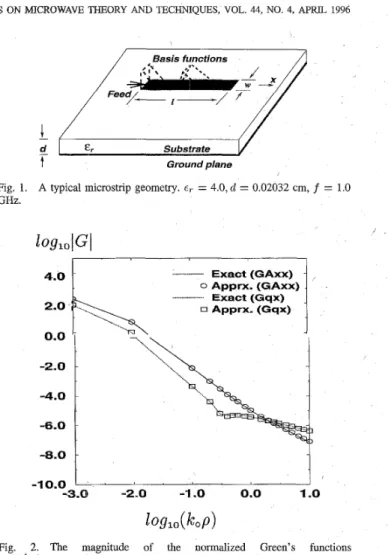
Fig. 1. A typical microstrip geometry. er = 4.0, d = 0.02032 cm, f = 1.0 GHz. 4.0 2.0 0.0 -2.0 -4.0 -6.0 Exact (GAxx) - 0 Apprx. (GAxx) . n Apprx. (Gqx) x Exact (Gqx)
j-
1.’r;l -1 -*.O 0.0 -3.0m
-2.0 -1.0 0.0 1.o
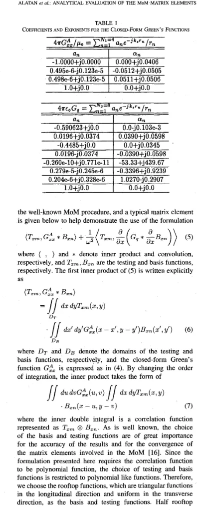
Fig. 2. The magnitude of the normalized Green’s functions 4 a G & , l p , , , 4 ~ ~ ~ G ~ . E , = 4.0, d = 0.02032 cm, f = 1.0 GHz.
where r l n =
dx2
+
y2 - atn and ~2~ = Jx2+
y2 - aZn 2 are the complex distances andk,
is the wave number in the source medium.As an example, consider the following parameters for the
geometry of a substrate backed by a ground plane as in Fig. 1 which shows the dielectric constant of the substrate E , = 4; the thickness of the substrate d = 0.02032 cm; and the frequency of operation f = 1.0 GHz. The Green’s functions of the vector and scalar potentials due to a HED at the air-substrate interface are obtained in closed forms via two-level approximation scheme, and the coefficients u l n , uzn and the exponents aln, azn are given in Table I along with the normalized Green’s functions for vector and scalar potentials, 47rG&/p, and 47re,Gq, respectively, in Fig. 2.
111. FORMULATION
This formulation is applicable to general microstrip geome- tries in a multilayer medium where it is assumed that the layers extend to infinity in the transverse directions. However, to avoid complexity and to emphasize the main idea of the proposed method, the formulation is presented, without loss
of generality, for a microstrip line on a substrate for which only the longitudinal current is assumed to exist.
The mixed-potential integral equation for the microstrip line can be transformed into the matrix equation with the use of
ALATAN et al.: ANALYTICAL EVALUATION OF THE MoM,MATRM ELEMENTS 521 an -0.590623+jO.O 0.0196+j0.0374 -0.4485+JO.O 0.0196-jO.0374 -0.260e-10+j0.771e-11 0.279e-5-jO.245e-6 0.204e-6+j0.328e-6 1 .O+jO.O
TABLE I functions are also used to model the current density at the
COEFFICIENTS AND EXPONENTS FOR THE CLOSED-FORM GREEN’S FUNCTIONS load and Source termin;& [ 131.
ffn 0 .O-j 0.103e-3 0.0390+j0.0598 O.O+j0.0345 -0.0390+j0.0598 -53.33+j439.67 -0.3396+j0.9239 1.0270-jO.2907 O.O+jO.O
For the above choice of the basis and testing functions, the correlation function becomes
where
l.O+jO.O
I
o.o+jo.o
f ( u ) =w3
+
y2u2+
Y l U+
yothe well-known MOM procedure, and a typical matrix element
( m - n - 2)h,< u
<
( m - n+
2)h,and yo, yl,y2,73 are constants determined by m, n, and h, (the half-span of the basis functions in 2-direction); and the length of the unit cell in1 y-direction, h,, is chosen to be equal to the width of the microstrip line for the specific geometry considered herein. It should be noted that the formulation given here is also valid for a 2-D patch since the order of
the polynomials in (9) 11s the highest that can be encountered in the analysis. By subslituting the correlation function (8) and the Green’s function (4) into (7), the inner-product term can be written as
D E
where DT and DE denote the domains of the testing and basis functions, respectively, and the closed-form Green’s function G;, is expressed as in (4). By changing the order of integration, the inner product takes the form of
(9)
is given below to help demonstrate the use of the formulation
5
a, [yo (hy11
dv du hz ,=I rn (Txm, G&*
~ x n )+
-
e - J k r n -I]
T v d v d u+
y1 (:hy//
e-jk,r.,u dv du - /J* e - c r nwhere (
,
) and*
denote inner product and convolution, respectively, and T,,,
B,, are the testing and basis functions, respectively. The first inner product of ( 5 ) is written explicitlyas rn
uv dv du (Txm, ,G!
*
~ x n )=
JJ
dXdyTxm(2,y)+
yz (:hy//
CU’
dv duD r rn
where the inner double integral is a correlation function represented as Txm 8 El,,. As is well known, the choice of the basis and testing functions are of great importance for the accuracy of the results and for the convergence of the matrix elements involved in the MOM [16]. Since the
formulation presented here requires the correlation function to be polynomial function, the choice of testing and basis functions is restricted to polynomial like functions. Therefore, we choose the rooftop functions, which are triangular functions in the longitudinal direction and uniform in the transverse direction, as the basis and testing functions. Half rooftop
where r, is either T I , or r2, as defined in
(4).
Because the integrals in
(IO)
occur in the calculation of matrix elements, and because they cannot be evaluated an- alytically, their numerical evaluations constitute almost the entire fill time of the MOM matrix. Although the use ofthe closed-form Green’s functions in conjunction with the
MOM improves the malrix fill time significantly [13], it could
be further improved if the integrals involved (IO) can be evaluated analytically. It has been shown that the Taylor’s series expansion of the exponential term in the integrand of the first integral in (IO) results in an analytically integrable function over a surfacle [17]. Using this fact, and some of the integral identities given in [18], we can evaluate the integrals in (10) analytically. The case of the Taylor’s series expansion requires examining its convergence for all rn values
522 IEEE TRANSACTIONS ON MICROWAVE THEORY AND TECHNIQUES, VOL. 44, NO. 4, APRIL 1996 with the same number of terms; therefore, the expansion
is performed around different center points R, for different regions corresponding to different basis and testing function pairs. The mth order Taylor series expansion of f ( x ) around z , involves an error term of
where c is a point in the region of convergence. As the mth derivative of e--31CsTn is bounded by k y , the error introduced by using the mth order expansion is
It can be observed that the distance to the center point directly determines the error. Hence, to minimize the error, the locations of the center points are chosen to be the mid- point of the each integration region for which the integration intervals are 2h, and 4h, for v and u integrations, respectively, and consequently, rn - R,
5
(2h ) 2+
h2. For the choice of 20 basis functions for each wavelength, rn - R, is bounded by 0.llX and the error is obtained in the following formJ-
(11) - (0.7)"+l ( m+
I)! - (27T x 0.11)"+1 error5
( m+
l)!from which it is easily shown that an error bounded by can be obtained with the use of at least five terms of the Taylor series. The results presented in Section IV demonstrate that the amount of error of lop4 or smaller does not affect the end result as the current distributions obtained by using analytic and numeric integrations are in good agreement. Hence, it is not worthwhile to increase the number of terms any further.
Using the fifth-order Taylor series expansion around R,, c - 3 ' s T n can be approximated as where k 2 R 2 k:R: kZRZ = (1 + j k , R , - -j,+- 24 2 k:RZ k:R: k:R: - j k s
+
k:Rc+
j y - __ - j ~ 6 24+-
4 p5 = - j - . 120Replacing the exponential term e - J k S T n in (10) by its Taylor series expansion given in (12) results in the integrals of the
rAukvzdudv f o r j = -1,0,...,4, k = 0 , . . . , 3 ,
1 = 0 , l . (13)
These integrals are analytically integrable and their results are given in the Appendix. Note that the same procedure presented above can be applied to the second inner-product term of ( 5 ) in which G, has the same functional form as G& given in (4).
rv.
RESULTS AND DISCUSSIONSIn this part of the study, the formulation described above is applied to a microstrip line to evaluate computational efficiency. The dielectric constant of the medium is cT = 4.0,
the ratio of line width w to substrate thickness d is 4.0. The thickness of the substrate is 0.02032 cm (= 8.0 mils.), the frequency is 1 GHz, and the length of the line is 10 cm. Computational efficiency of the proposed, method is assessed in terms of the CPU (central processing unit) time obtained from a SUNsparc-10 workstation.
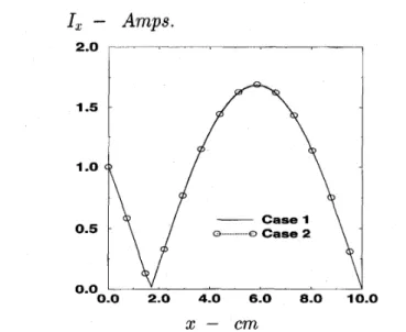
The current distribution on the microstrip line is obtained by numerically integrating the double integrals (7) (Case 1) involved in the MOM matrix elements, and then by using the analytic integration formulation presented in Section I11 (Case 2). The current distributions obtained via the use of the numerical integration (Case 1) have been verified by comparing it with the results obtained via the transmission line method described in [13]; therefore, Case 1 serves here as a reference for the accuracy of the current distribution as \
well. In the numerical integration, 16-point Gauss quadrature integration algorithm, which is considered to be one of the fastest numerical integration algorithms, is employed for the double integrals for which the range of the integration is divided into subregions to guarantee the convergence of the numerical integration. For both cases, the CPU times are obtained for different numbers of basis functions and are listed in Table 11. The current distributions obtained via numerical and analytical evaluations of the integrals for 40 basis functions are shown in Fig. 3. It can be observed from Table I1 that the elimination of the numerical integrals reduces the computation time approximately by a factor of 40. Besides the improvement in computational efficiency, the formulation based on the analytical integration also provides a number of other advantages. First, as the MOM becomes a technique free from any numerical integrations, the numerical errors due to integration and the time used to find an appropriate numerical integration algorithm are eliminated. Second, as the matrix entries are expressed in closed-forms, the effect of changes in geometrical parameters, such as length and width of the microstrip line, onto the output parameters like, current distribution, input impedance or spurious radiation, can- be studied analytically by taking a derivative with respect to the desired parameter. Finally, if a method uses numerical integrations, it is necessary to extract the singularity at the source point, while in the analytic integration formulation this problem is completely eliminated because the singularities involved are integrable over a surface. It should be noted that
ALATAN et al.: ANALYTICAL EVALUATION OF THE MOM MATRIX ELEMENTS 523
basis func. 10
20
APPENDIX
THE ANALYTIC EVALUATION OF THE INTEGRALS GIVEN IN ( 13)
I,
-
Amps.
R =
du2 +
v2+
c2where c is any of the complex exponents. Some special integrals are defined in order to simplify the formulation
J o = / R d u = Z ( R u + ( v 2 + c 2 ) 1
.
log (u+
R ) ) R3 J 1 =s
u R d u = - 3-
Case1 0 o C a s e 2 J2 =1
u2R d u u(v2+
c2+
2u2)R.
log ( U+
R ) (u2+
c2)’-
- - 0.0 2.0 4.0 6.0 8.0 10.0 8 8x
-
c mFig. 3. Current distributions obtained by using 40 basis functions.
er = 4.0,d = 0.02032 cm, f = 1.0 GHz, w = 0.08128 cm, 2 = 10 cm. R5 R3 5 3 J3 = / u 3 R d u =
-
- ( v 2+
c 2 ) - (Case 1) (Case 2) 13.3 0.36 27.0 0.65 TABLE I1CPU TIMES FOR DIFFERENT NUMBER OF BASIS FUNCTIONS
number of
I
CPU time in sec.I
CPU time in sec.30 39.0 0.98
40 52.95 1.33
the application of the proposed approach here has no restriction for the size of the geometry, provided the closed-form Green’s functions are valid for the distance as far as the maximum distance of the geometry.
V. CONCLUSION
When the spatial-domain MOM is used in conjunction with the closed-form Green’s functions for the solution of the mixed-potential integral equation, the MOM matrix elements involve 2-D integrals whose numerical evaluations increase the matrix fill-time. In order to improve the numerical effi- ciency of the method, the integrand is approximated by its Taylor series and each term of the expansion is integrated analytically. By eliminating the numerical integration from the
MOM, the matrix fill-time is decreased drastically, which is a significant improvement in the matrix-fill time of the MOM.
This acceleration in the matrix fill time makes the MOM a
fast full-wave analysis technique which can be utilized in an optimization algorithm for the solution of a design problem. Besides, the proposed method offers other advantages such as expressing the matrix entries in closed-forms, which opens up the possibility of investigating the effect of some parameters on the end result by examining the matrix entries analytically.
54 =
.I
u4Rdu =(-tc$
+
c 2 ) 2+
(v2+
c2)u2+
4u4)(g)
1 16 R7 2 u5Rdu = - - -R5(v2+
c 2 )+
-(v2+
c 2 ) 3 log ( u+
R ) J5 =s
7 5 R3 3+
-(v2 + c y R9R7
9 7 - 3(v2 f e z ) - + 3 ( v 2 + c ) 2 R 5 - - ( v 2 + c ) 2 3R3 - 5 3 KO =/
du = l o g ( u + R ) K1 = / % d u = R Kn =/
$
du = Jn-2-
(w2+
c 2 ).
Kn-2524 IEEE TRANSACTIONS ON MICROWAVE THEORY AND TECHNIQUES, VOL. 44, NO. 4, APRIL 1996
U [5] D. M. Pozar, “Input impedance and mutual coupling of rectangular
microstrip antennas,” IEEE Trans. Antennas Propagat., vol. AP-30, pp. 1191-1196, Nov. 1982.
[6] J. R. Mosig and F. E. Gardiol, “General integral equation formulation for microstrip antennas and scatterers,” ZEE Proc., pt. H, vol. 132, no. 7, pp. 424432, 1985.
[7] A. Sommerfeld, Partial Dijjerential Equations in Physics. New York: Academic, 1949.
[SI W. C. Chew, Waves and Fields in Inhomogeneous Media. New York: Van Nostrand, 1990.
[9] Y. L. Chow, J. J. Yang, D. F. Fang and G. E. Howard, “Closed form spatial Green’s function for the thick substrate,” IEEE Trans. Microwave
Theory Tech., vol. 39, pp. 588-592, Mar. 1991.
[lo] M. 1. Aksun and R. Mittra, “Derivation of closed-form Green’s functions for a general microstrip geometries,” IEEE Trans. Microwave Theory
Tech., vol. 40, pp. 2055-2062, Nov. 1992.
[1 11 G. Dural and M. I. Aksun, “Closed-form Green’s functions for general sources and stratified media,” IEEE Trans. Microwave Theory Tech., vol. 43, no. 7, pp. 1545-1552, Jul. 1995.
[12] M. I. Aksun, “A robust.approach for the derivation of the closed-form Green’s functions,” IEEE Trans. Microwave Theory Tech., in press. [13] M. I. Aksun and R. Mittra, “Estimation of spurious radiation from
microstrip etches using closed-form Green’s functions,” ZEEE Trans.
Microwave Theory Tech., vol. 40, pp. 2063-2069, Nov. 1992.
1141 N. K. Das and D. M. Pozar, “A spectral-domain Green’s function for multilayer dielectric substrates with application to multilayer transmis- sion lines,” IEEE Trans. Microwave Theory Tech., vol. MTT-35, pp. 326335, Mar. 1987.
[15] Y. Hua and T. K. Sarkar, “Generalized pencil-of-function method for extracting poles of an EM system from its transient response,” IEEE
Trans. Antennas Propagat., vol. 37, pp. 229-234, Feb. 1989.
[16] M. I. Aksun-and R. Mittra, “Choices of expansion and testing functions for the method of moments applied to a class of electromagnetic problems,” ZEEE Trans. Microwave Theory Tech., vol. 41, pp. 503-509, Mar. 1993.
[17] R. F. Hanington, “Matrix methods for field problems,” Proc. IEEE, vol. 55, pp. 136-149, Feb. 1967.
[18] K. Mahadevan and H. A. Auda, “Electromagnetic field of a rectangular patch of uniform and linear distributions of current,” ZEEE Trans.
Antennas Propagat., vol. 37, pp. 1503-1509, Dec. 1989.
du I’ =
I
(u2+
c 2 ) R 2w In =1
(u2+
c2)R - - log ( R - v) - log ( R+
v ) U n du = Kn-2 - c2In_2 1 du Lo =.I
(u2+
3 ) L1 =I
(u2+
c2) 1 c = - arctan(:)
U log ( u2+
2)
2 du = Un-l 2 c Ln-2 du=-- U n Ln =1
(u2+
c2) n/15, = J J $ d v d u n - 1 = (un+’ log (W+
R ) - Ln+2+
wIn+2)/(n+
1) 1 2 Un+l(;
+ve?)+
n+3v unR2dv
du = - n + 1 unR dw du = -(wJn+
Mn+z+
c2Mn) ; ~ n + 3I/
v ( 5 c 2)
/J
SS
Un+l (c4w+ 7
+
-I .
n + l v 5 2c2v3) 3 4 2 5 8 unR3 dv du = -vJn+2+
- -+
v 2 Jn 3+
g
( ~ n + 4+
2 c 2 ~ n + 2+
c 4 ~ n ) unR4 dv du = - n + 3//
%
dw du = Jn Un+3w2 “2.( “ 2 ) Un+l11
unwR2 dv du = 2 ( n + 3 ) 2 2 n + l ~+ -
e + - - J n + 4 2(v2+
2)
unvR3 dv du = ~+
Jn+2I/
5(2
+
c y + 5 J nLale Alatan (S’91) received the B.S. and M.S. degrees in electrical and electronics engineering from Middle East Technical University (METU), Ankara, Turkey, in 1990 and 1993, respectively. Currently, she is working toward the Ph.D. degree at METU.
Her research area includes numerical analysis of printed structures, microstrip antennas, and mi- crowave and millimeter-wave circuits.
U n+ 5 v 2 Un+3 unvR4 dw d u = ~
/I
REFERENCES
[ l ] R. F. Hmington, Field Computation by Moment Methods. New York MacMillan; FL; Krieger, 1983.
[2] J. Jin, The Finite Element Method in Electromagnetics. New York Wiley, 1993.
[3] K. Kunz and R. Luebber, The Finite Difference Time Domain Method
f o r Electromugnetics.
[4] R. Schinzinger and P. Laura, Conformal Mapping: Methods and Appli-
cations. New York: Elsevier, 1991.
Boca Raton, FL: CRC, 1993.
M. I. Aksun (M’92) received the B.S. and M.S. degrees in electrical and electronics engineering from the Middle East Technical University, Ankara, Turkey, in 1981 and 1983, respectively, and the Ph.D. degree in electrical and computer engineering from the University of Illinois at Urbana- Champaign in 1990. From 1990 to 1992, he was a Post Doctoral Fellow at the Electromagnetic Communication Laboratory, University of Illinois at Urbana-Champaign.
Since 1992, he has been on the Faculty of the Department of Electrical and Electronics Engineering at Bilkent University, Ankara, Turkey, where he is currently an Associate Professor. His research interests include the numerical methods for electromagnetics, microstrip antennas, and microwave and millimeter-wave integrated circuits.
ALATAN et al.: ANALYTICAL EVALUATION OF THE MOM MATRIX ELEMENTS 525
Karthikeyan Mahadevan was born in Thanjavur, India, on December 1, 1957. He received the B.E. degree with honors in electronics and communi- cation engineering from the Regional Engineering College, Tiruchirappalli, India in 1980; the M.S. degree in electrical engineering from the Indian Institute of Technology (IIT), Madras, India, in 1983; and the Ph.D. degree in engineering science from the University of Mississippi, University, in 1991.
From 1980 to 1986, he was with the Center for Systems and Devices, IIT, working on a development project in electromag- netics and antennas sponsored by the Defense Research and Development Organization of the Government of India. In 1986, he joined the Department of Electrical Engineering of the University of Mississippi as a Graduate Research Assistant. From 1991 to 1993, he worked in the Electromagnetic Communication Laboratory of the University of Illinois as a Post Doctoral Fellow. In 1994, he joined SG Microwaves Inc., Kitchener, Ontario, Canada as an Advanced Technical Member. His areas of interest include electromagnetic field theory and computation.
M. Tuncay Birand (S’67-M’72) received the B.S., M.S., and Ph.D. degrees from Middle East Technical University (METU), Ankara, Turkey, in 1966,1967, and 197 1, respectively.
]He was a Visiting Professor at the Queen Mary College, England, from 1978 to 1979, and at the University of Illinois, Department of ECE on a Fullbright program from 1988 to 1989. He was a Consultant with the ERA Tech. Ltd., Radio Fre- quency Technical Division, Leatherhead, England, from 1979 to 1981. He was Chairman of the EE Department, Gazi University, Turkey, from 1982 to 1983, and from 1984 to 1988, and the Chairman of the EE Department of METU from 1991 to 1992. He is the National Representative in the Senior Officials Committee of the European Cooperation in the Field of Scientific and Technical Research. Currently, he is the Dean of the Faculty of Engineering, METU, Ankara, Turkey. His research interests are antenna near-field and far-field transfoma- tions, printed antennas and computational electromagnetics.
Dr. Birand won the Promotion Award of the Turkish Scientific and Research Council in 1983. He is a member of the Chamber of Electrical Engineers of Turkey and the New York Academy of Sciences.