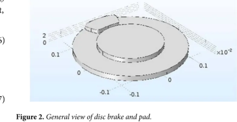
Three-Dimensional Cfd Modeling Of Thermal Behavior Of A Disc Brake And Pad For An Automobile
Tam metin
Şekil

Benzer Belgeler
The working group of research consists of 30 Social Sciences Teachers having the application of branch classrooms in their schools in Kastamonu. In the research, ‘Interview
Table shows the risk factors, clinical presentations and imaging findings with respect to the dissection types.. Eleven patients had a history
l The cell membrane in species belonging to these families is composed by a thin structure called plasmalemma. l Therefore, body shape of these protozoa is not fixed and they move
In 1997 he graduated from Güzelyurt Kurtuluş High School and started to Eastern Mediterranean University, the Faculty of Arts and Sciences, to the Department of Turkish Language
She started working as a full time lecturer in the Department of Psychological Counseling and Guidance at Near East University in 2015.She has been a lot of Seminars
2013 She has been working as Research Assistant and Teach in Computer Engineering of the Near East University since 2002. 2015 She has been as lecturer in Computer Engineering of
Ceftolozane is a novel cephalosporin antibiotic, developed for the treatment of infections with gram-negative bacteria that have become resistant to conventional antibiotics.. It was
Good water quality can be maintained throughout the circular culture tank by optimizing the design of the water inlet structure and by selecting a water exchange rate so
