ORIGINAL PAPER
Nanoparticle-Implanted-CNTs www.crt-journal.org
A Bean-Like Formation of Germanium Nanoparticles Inside
CNTs by the Subsequent Operation of Colloidal Synthesis
and Catalytic Chemical Vapor Deposition Methods
Ali Karatutlu,* Filippo S. Boi,* Rory M. Wilson, Osman Ersoy, Bulend Ortac,
and Andrei Sapelkin
The first attempts of implanting Ge nanoparticles (Ge NPs) inside iron filled CNTs (IF-CNTs) by a subsequent use of the bench top colloidal synthesis and chemical vapor deposition (CVD) approach is shown. Ge NPs are colloidally synthesized (with a 3.8± 0.6 nm in size) before the deposition. The hybrid Ge NPs/IF-CNTs structure and morphology are characterized using
high-resolution transmission electron microscopy, scanning electron microscopy, selective area electron diffraction, and X-ray diffraction studies. After the deposition, Ge NPs appear to be grown in size and to be sprinkled almost homogeneously into the IF-CNTs similar to a bean-like deposition. CNTs diameter is also identified to be enlarged drastically when using Ge NPs as a catalyst in CVD compared to the CNTs formation without Ge NPs. In addition, micro-length rectangular GeµPs are also found outside the nanotube core. Rietveld analysis shows the presence ofγ -Fe (Fm-3m), ferromagneticα-Fe (Im-3m), Fe3C, Ge (Fd-3m), and multiwall CNTs. The
results indicate that Ge NPs and IF-CNTs demonstrate cocatalytic activity in increasing the respective sizes, which are dramatically larger than those obtained by the conventional approaches.
Dr. A. Karatutlu, Dr. B. Ortac
Institute of Materials Science and Nanotechnology and UNAM-National Nanotechnology Research Center
Bilkent University Ankara 06800, Turkey
E-mail: [email protected] Dr. F. S. Boi
College of Physical Science and Technology Sichuan University
Chengdu, 610064, P. R. China E-mail: [email protected] Dr. R. M. Wilson
School of Engineering and Material Science Queen Mary University of London London, E1 4NS, UK
Dr. O. Ersoy, Dr. A. Sapelkin
Centre for Condensed Matter and Materials Physics School of Physics and Astronomy
Queen Mary University of London London, E1 4NS, UK
The ORCID identification number(s) for the author(s) of this article can be found under https://doi.org/10.1002/crat.201800123 DOI: 10.1002/crat.201800123
1. Introduction
Multiwall CNT-based formation of mag-netic/dielectric composite structure is an emerging field for many applications including enhancing microwave absorp-tion properties of funcabsorp-tional materials[1]
and nanodiodes.[2] Such materials
are also considered as a fundamental strengthening block onto the various surfaces where it is applied.[3]
Further-more, transition-metal filled CNTs were demonstrated to be significant in con-trolling magnetic field with the amounts of ferromagnetic metal fillings.[4] Such
a requirement is useful particularly for biomedical applications such as targeted therapeutics.[5] Ferromagnetic iron
fill-ings inside CNTs were demonstrated to be continuous in micrometer length[6]
using catalytic chemical vapor deposition (CVD) approaches. Three main crystal structures are generally observed such as Fe3C,α-Fe, and γ -Fe.[7–11] Creating a single phase of
ferromag-neticα-Fe encapsulated by CNTs is the ultimate purpose de-spite the fact that other two phases could be unavoidable upon the synthesis and perhapsγ -Fe could be transformed to α-Fe by the post-synthesis approaches.[12]In order to achieve the growth
of such CNTs structures, the use of several catalysts including organometalocenes such as ferrocene, thin film catalysts coated on the flat substrates, and metals or bulk metals have been re-ported. In particular, the advantage of metallocene precursors consists in their relatively low evaporation and decomposition temperatures.[13]On the other hand, porous structures were also
shown to possess a catalytic support for CNTs formation.[14]Until
now, few studies on the formation of nanocomposites prepared by Ge NCs implantation in CNTs were demonstrated using the CVD technique[15,16]and carbonization/annealing process.[17]
De-spite the intense research on the various forms of the catalysts and CNTs formation using different methods, to the best of our knowledge, no reports have yet shown experiments on implanta-tion of metal/semiconductor juncimplanta-tion of Fe and Ge inside a sin-gle CNT. Such systems could have important implications for the formation of quantum dot devices along CNTs with 1D electronic properties.
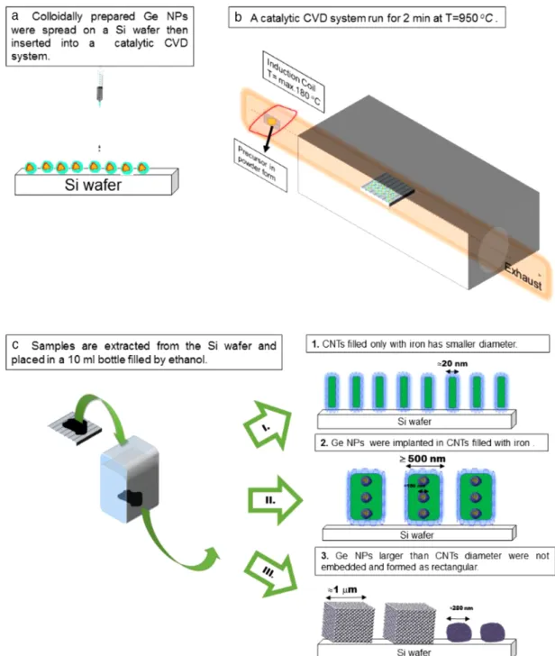
Figure 1. Schematic of formation of I) Ge NPs implanted IF-CNTs, II) only IF-CNTs, and III) rectangular GeµCs.
In this paper, we represent the first experiments on implanta-tion of Ge NPs inside IF-CNTs. We show that colloidal Ge NPs induce a not previously observed giant growth of the CNTs struc-tures with a consequent dramatic increase in the diameter of the obtained nanostructures. The morphology and structure of the CNTs were demonstrated using complementary techniques including high-resolution scanning electron microscopy (HR-SEM), transmission electron microscopy (TEM), selective area electron diffraction (SAED), and X-ray diffraction (XRD) studies. Along with Ge NPs implanted iron filled CNTs, other types of CNTs filled with the only iron phases and rectangular Ge
micro-crystals (µCs) were obtained using this approach. Iron-carbide filled CNTs were found to possess an unusual morphology with a diameter ofࣈ10 µm.
2. Results and Discussion
Schematic of the CNTs formed with a subsequent use of colloidal synthesis and a catalytic CVD system is demonstrated in Figure 1. Using the recipe mentioned above, formation of three different
www.advancedsciencenews.com www.crt-journal.org
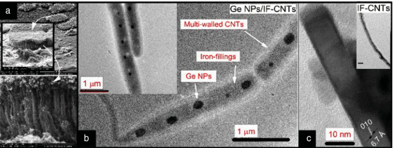
Figure 2. a) SEM and b) TEM images of the CNTs. The SEM images in (a) and the insets show carpet-like patterns radially grown in 2D with a diameter
and height of the order of 200 and 40µm, respectively. In (b), two different tubes of Ge NPs/IF-CNTs side to side and next to each other are represented, respectively. c) The presence of forbidden 010 reflection corresponding to a lattice spacing of 6.7 ˚A is represented for Fe3C filled CNTs. The TEM
micrograph shown in the inset in (c) is given for iron fillings of IF-CNTs where the scale bar is 50 nm.
structures was mainly observed: I) Ge NPs implanted IF-CNTs, II) only IF-CNTs, and III) rectangular GeµCs.
Figure 2 shows HR-SEM and TEM images, which respectively represent carpet-like CNTs and Ge NPs implanted throughout IF-CNTs. A typical TEM image is shown in Figure 2b. Ge NPs were clearly demonstrated to be spread with a bean-like shape. The size of embedded Ge NPs was found to be 152± 43 nm. The diameter of the IF-CNTs containing Ge NPs was found to be 497.5 ± 35 nm in size. Such Ge NPs embedded IF-CNTs were named Ge NPs/IF-CNTs. On the other hand, in the inset given in Figure 2c, the TEM of only IF-CNTs without Ge NPs was represented to show the diameter of the CNTs reducing to less than 60 nm. Thus, Ge NPs appear to show a catalytic behavior which leads to a vivid increase in the size of CNTs.
Figure 3a,b demonstrates the morphology of flower-like CNTs at an average bundle diameter of 10µm. Interestingly, the pres-ence of a uniform bundle thickness is found. GeµCs not filled inside CNTs are shown in Figure 3c. The unfilled Ge NPs were determined to be 1.2± 0.6 µm in size out of 100 counts. This size is larger than the inlet/exit diameter of the Ge NPS/IF-CNTs. On the other hand, we studied the effect of annealing of the as-prepared Ge NPs for various hours without sending the ferrocene vapor to see the catalytic effect of the IF-CNTs on the size of Ge NPs both in various hours of H2Ar gas medium[18] and 1 h of
Ar gas medium (D: 4.49± 0.98 nm). The sizes of the annealed Ge NPs at average in both media were much smaller than with-out the CNTs growth. Therefore, not only Ge but also the IF-CNTs were suggested to show the catalytic activity for increasing the size of one another dramatically, whereas the diameter of the IF-CNTs without embedding Ge NPs was preserved as in the or-ders of those previously reported in the literature. Besides, the annealing process of the colloidally synthesized Ge NPs were carried out and resulted in Ge NPs with almost spherical NPs in the Ar gas flow of 50 sccm (see Figure S2, Supporting Infor-mation). This also supports an indication that Ge NPs/IF-CNTs (or IF-CNTs) samples act as a support during the heterogeneous formation reaction of the rectangular Ge NPs. Thus, Ge and the IF-CNTs can be proposed to be cocatalysts. In some places, the unembedded Ge NPs retained its spherical shape and recorded a
Figure 3. a) The flower-like IF-CNTs forming b) CNTs bundles. c) The SEM
image of rectangular-shaped GeµCs with a mean size of 1.2 ± 0.5 µm, and d) the SEM image of one GeµC just before the completion of the formation of its rectangular shape. The mean size of the CNTs both for the flower-like and the CNT bundles was estimated from the size distributions (SD) out of 60 counts. The mean size of the rectangular Ge NPs was found from the SD using 100 counts.
mean size of 280± 130 nm, which is quite smaller compared to the rectangular Ge NPs (1.2± 0.6 µm). Therefore, two-step nu-cleation and growth mechanism[19]seem to be playing a role in
the formation of the rectangular Ge NPs. Nevertheless, further studies are essential in order to support this scheme.
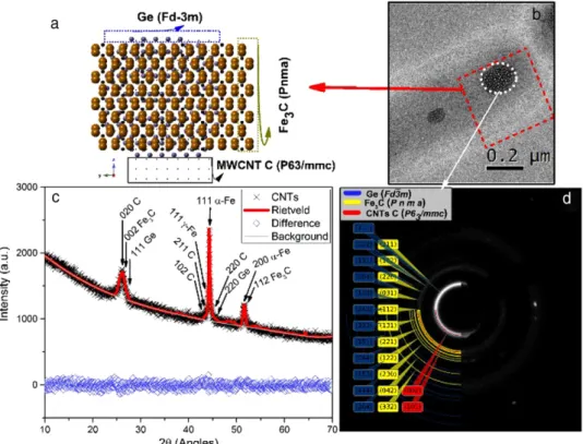
Figure 4 shows the XRD data from the samples extracted from the reactor and Rietveld analysis to represent the composition of the different phases. The presence ofγ -Fe (F m¯3m)/α-Fe (Im¯3m), Ge (F d ¯3m), CNT graphite (P63/mmc), and Fe3C (P n m a) was
revealed. The relative abundances of the crystalline phases are demonstrated in Table 1. The phases were, respectively, estimated to be 9.5% for the γ -Fe (from the 111 diffraction peak of the
Figure 4. a) The schematic of the crystal structures to represent the structure from the cross-sectional rectangular area (red) shown in (b). The blue dots,
gold/black dots given together and only black dots illustrate, respectively, the Ge (F d ¯3m), Fe3C (P n m a), and CNT graphite (P63/mmc) crystal structures.
For clarity, the scheme does not representγ -Fe (F m¯3m) and α-Fe (I m¯3m) crystal structures. b) The TEM micrograph of the Ge NPs/IF-CNTs. c) The XRD data (crosses) from the material collected from the reactor, Rietveld analysis (red line), the background (grey line), and the difference between the data and the fit (blue diamonds). Rietveld analysis results in theγ -Fe (F m¯3m)/α-Fe (I m¯3m), Ge (F d¯3m), CNT graphite (P63/mmc), and Fe3C
(P n m a). d) The SAED from the area shown by a circle (white) in (b). The simulation represents a good fit to the SAED data using the diamond structure
of Ge (F d ¯3m) and the CNT graphite (P63/mmc).
Table 1. The relative abundances of the structural phases estimated using
the Rietveld analysis of the XRD data (average) and the diffraction ring simulation (local) on the SAED data.
Phases (space groups) % Relative
abundance (the XRD data)
% Relative abundance (the SAED data on a single Ge NPs/IF-CNTs) Ge (F d ¯3m) 38.1 29.5 γ -Fe (F m¯3m) 9.5 – α-Fe (I m¯3m) 4.8 – CNT graphite (P63/mmc) 9.5 46.9 Fe3C (P n m a) 38.1 23.4
F m¯3m space group), 4.8% for the α-Fe (from the 111 and 200
diffraction peaks of the Im¯3m space group), 38.1% for Ge (from the 111 and 220 diffraction peaks of the F d ¯3m space group), 9.5% for MWCNT graphitic C (from the 020, 211, 102, and 220 diffrac-tion peaks of the P63/mmc space group), and 38.1% for the Fe3C
(from the 002 and 112 diffraction peaks of the P n m a space group).
Likewise, further structural analyses were done using the SAED studies. The SAED data of the Ge NPs/IF-CNTs are shown in Figure 4d in which the diffraction measurement was taken
from the cross-sectional area of one single Ge NP inside the Ge NPs/IF-CNTs. The simulation using the Ge (F d ¯3m), the CNT graphite (P63/mmc), and the Fe3C (P n m a) crystal structures
obtained from the Rietveld analysis shows a good fit to the elec-tron diffraction data. Such a simulation can give information about the relative intensity of the scattering vector from the cor-responding crystal structures. Therefore, a relative percentage of each structure was estimated from the peak intensity of the Ge ((111) of F d ¯3m), the CNT graphite ((002) of P63/mmc), and the
Fe3C ((031) of P n m a) crystal structures which resulted,
respec-tively, in the percentage of 29.5, 46.9, and 23.4. Nevertheless, we consider that this estimation is only based on the assumption of the existence of only three phases. The peak betweenࣈ0.8 and 1.0 ˚A−1in the scattering wave vector (Figure S3, Supporting In-formation) suggests the existence of additional phases including
γ -Fe (F m¯3m) and α-Fe (Im¯3m). Furthermore, a similar approach
was applied to the IF-CNT shown in Figure 2c. The SAED of the IF-CNTs (Figure S4, Supporting Information) confirms both the presence of the CNT graphite (P63/mmc) and Fe3C (P n m a)
phases with an agreement to the crystal structures found from the XRD studies. On the other hand, the crystal structure of the unfilled spherical Ge NPs was determined using the SAED from one single NP (Figure S5, Supporting Information). Here, the SAED from this Ge NP is given together with the simulation done by the Ge (F d ¯3m) crystal structure (a = b = c = 5.4 ˚A,α = 90°,
www.advancedsciencenews.com www.crt-journal.org
β = 90°, γ = 90°. Such Ge NPs were considered to be exposed
to the thermal stress[20]during the growth and cooling processes,
thus a shrinkage in the lattice compared to its bulk counterparts (a= b = c = 5.657 ˚A, α = 90°, β = 90°, γ = 90° from ICDS ID = 43 422) becomes possible. Such change in the structure upon the thermal stress suggests to yield formation of the dislocations which in return can serve as a seed for obtaining rectangular Ge µCs.
3. Conclusion
In summary, we have shown the first attempt of the Ge NPs im-planted IF-CNTs using an assembled catalytic CVD system. Fur-thermore, the rectangular GeµCs and the CNT bundles in the order of micrometer length obtained as a side product of this het-erogeneous reaction. The growing atmosphere containing both ferrocene vapor and Ge NPs seem to possess a catalytic activ-ity in increasing the size of Ge NPs and the Ge NPs/IF-CNTs. The unembedded GeµCs were driven out to be rectangular after the deposition, showing an indication of two-step nucleation and growth mechanism for rectangular Ge NPs possible.
4. Experimental Section
Synthesis of the Colloidal Ge NPs: All chemicals were purchased from
Sigma-Aldrich and used as purchased. Preparation of colloidal synthesis was mentioned in our previous studies,[21,22]which yielded the colloidal
Ge NPs with an average size of 3.89± 0.61 nm determined by TEM.
Catalytic Chemical Vapor Deposition of the Ge NPs in IF-CNTs: 1 mL of Ge
NPs dispersed in ethanol was placed via drop casting on top of a Si wafer (or a quartz boat) inside a catalytic CVD system. After the insertion of the Ge NPs inside the CVD system, the reactor was heated for the operation at 950°C. As a precursor, 50 mg of ferrocene was used which was heated by a conduction coil for its sublimation. Then, the reaction was initiated by a flow of 50 sccm Ar gas and completed at the end of 2 min when the furnace was quenched (removed along a rail system) immediately afterward.
Characterization: The samples were collected and placed in ethanol
prior to their characterization. The TEM and SAED measurements were taken using a JEOL 2010 to distinguish Ge NPs, iron fillings, and CNT walls and for further structural analysis. HR-SEM measurements were per-formed using an FEI Inspect F microscope for the morphology of CNTs in general. XRD measurements were taken using a Panalytical X’Pert Pro diffractometer (Panalytical BV, Almelo, Netherlands) (with Cu Kα sources with λ = 0.15418 nm). The Rietveld analysis was completed using a
GSAS code[23,24]with a GSAS+EXPGUI software package (Version:
Re-vision 1251). The Chebyshev function was chosen to serve as the func-tion by the eight terms for having minimum reducedχ2. A commercial
software called Crystal maker and a freely available software called Mer-cury obtained from the Cambridge Crystallographic Data Centre (CCDC) were utilized for obtaining the crystal structure. The crystal structures were confirmed further using the SAED measurements, which were simulated using a package called Diffraction Ring Profiler.[25]The original SAED
mea-surements are given in Figure S1, Supporting Information, in the online supplementary file.
Supporting Information
Supporting Information is available from the Wiley Online Library or from the author.
Acknowledgements
The authors acknowledge the support provided by Queen Mary, University of London. The authors also thank Dr. Selcuk Atalay for fruitful discussions on the CNTs growth mechanism (Maxwell Institute for Mathematical Sci-ences and School for Mathematical and Computer SciSci-ences, Heriot–Watt University).
Conflict of Interest
The authors declare no conflict of interest.
Keywords
CNTs, colloidal, chemical vapor deposition, ferromagnetism, germanium, nanoparticles
Received: June 7, 2018 Published online: October 22, 2018
[1] H. Lv, G. B. Ji, H. Q. Zhang, Y. W. Du,RSC Adv. 2015, 5, 76836.
[2] P. A. Hu, K. Xiao, Y. Liu, G. Yu, X. B. Wang, L. Fu, G. Cui, D. Zhu,Appl. Phys. Lett. 2004, 84, 4932.
[3] F. Cervantes-Sodi, J. J. Vilatela, J. A. Jim´enez-Rodr´ıguez, L. G. Reyes-Guti´errez, S. Rosas-Mel´endez, A. ´I˜niguez-R´abago, M. Ballesteros-Villarreal, E. Palacios, G. Reiband, M. Terrones,Carbon 2012, 50,
3688.
[4] A. Nagata, H. Sato, Y. Matsui, T. Kaneko, Y. Fujiwara,Vacuum 2013, 87, 182.
[5] M. J. Rybak-Smith, C. Tripisciano, E. Borowiak-Palen, C. Lamprecht, R. B. Sim,J. Biomed. Nanotechnol. 2011, 7, 830.
[6] F. S. Boi, G. Mountjoy, R. M. Wilson, Z. Luklinska, L. J. Sawiak, M. Baxendale,Carbon 2013, 64, 351.
[7] F. S. Boi, G. Mountjoy, Z. Luklinska, L. Spillane, L. S. Karlsson, R. M. Wilson, A. Corrias, M. Baxendale,Microsc. Microanal. 2013, 19, 1298.
[8] U. Weissker, S. Hampel, A. Leonhardt, B. B¨uchner,Materials 2010, 3,
4387.
[9] J. F. Marco, J. R. Gancedo, A. Hernando, P. Crespo, C. Prados, J. M. Gonz´alez, N. Grobert, M. Terrones, D. R. M. Walton, H. W. Kroto,
Hyperfine Interact. 2002, 139/140, 535.
[10] C. N. R. Rao, R. Sen, Y. Z. Lu, S. Fan, C. M. Lieber, K. Kordatos, W. K. Hsu, J. P. Hare, P. D. Townsend, K. Prassides, A. K. Cheetham, H. W. Kroto, D. R. M. Walton,Chem. Commun. 1998, 375, 1525.
[11] R. Sen, A. Govindaraj, C. N. R. Rao,Chem. Phys. Lett. 1997, 267, 276.
[12] F. S. Boi, Y. Hu, J. Wen,RSC Adv. 2017, 7, 25025.
[13] M. Kumar, inCarbon Nanotubes—Synthesis, Characterization, Applica-tions, InTech, London 2011.
[14] D. Carta, F. Boi, A. Corrias, S. Bullita, Z. K´onya, M. F. Casula,J. Porous Mater. 2014, 21, 1123.
[15] G. A. Domrachev, A. M. Ob’edkov, B. S. Kaverin, A. A. Zaitsev, S. N. Titova, A. I. Kirillov, A. S. Strahkov, S. Y. Ketkov, E. G. Domracheva, K. B. Zhogova, M. V. Kruglova, D. O. Filatov, S. S. Bukalov, L. A. Mikhal-itsyn, L. A. Leites,Chem. Vap. Deposition 2006, 12, 357.
[16] G. Cui, L. Gu, N. Kaskhedikar, P. A. van Aken, J. Maier,Electrochim. Acta 2010, 55, 985.
[17] H. Guo, B. Ruan, L. Liu, L. Zhang, Z. Tao, S. Chou, J. Wang, H. Liu,
Small 2017, 13, 1.
[18] A. Karatutlu, O. Ersoy, W. R. Little, Y. Zhang, A. V Sapelkin, presented at Proc. of the World Congress on New Technologies(NewTech 2015), Barcelona, Spain, July 2015, Paper No. 386.
[19] P. G. Vekilov,Nanoscale 2010, 2, 2346.
[20] A. R. Chaudhuri, J. R. Patel, L. G. Rubin,J. Appl. Phys. 1962, 33, 2736.
[21] A. Karatutlu, W. Little, O. Ersoy, Y. Zhang, I. Seker, A. Sapelkin,J. Appl. Phys. 2015, 118, 244303.
[22] A. Karatutlu, M. Song, A. P. Wheeler, O. Ersoy, W. R. Little, Y. Zhang, P. Puech, F. S. Boi, Z. Luklinska, A. V. Sapelkin,RSC Adv. 2015, 5, 20566.
[23] B. H. Toby,J. Appl. Crystallogr. 2001, 34, 210.
[24] A. C. Larson, R. B. Von Dreele, General Structure Analysis Sys-tem (GSAS), 2004. https://www.ems.psu.edu/˜ryba/coursework/ Advanced%20Powder%20Diffraction/GSASManual.pdf (accessed: September 2016).
[25] L. Zhang, C. M. B. Holt, E. J. Luber, B. C. Olsen, H. Wang, M. Danaie, X. Cui, X. Tan, V. W. Lui, W. P. Kalisvaart, D. Mitlin,J. Phys. Chem. C 2011,115, 24381.