Procedia CIRP 14 ( 2014 ) 377 – 382
2212-8271 © 2014 Published by Elsevier B.V. Open access under CC BY-NC-ND license.
Selection and peer-review under responsibility of the International Scientific Committee of the 6th CIRP International Conference on High Performance Cutting
doi: 10.1016/j.procir.2014.03.006
ScienceDirect
6th CIRP International Conference on High Performance Cutting, HPC2014
Experimental Investigations on Micro Milling of Stavax Stainless Steel
S. N.B Oliaei
a, Y. Karpat
a,b*
aBilkent University, Department of Mechanical Engineering, Ankara 06800, Turkey bBilkent University, Department of Industrial Engineering, Ankara 06800, Turkey
* Corresponding author. Tel.: +90-312-2902263; fax: +90-312-2664054. E-mail address: ykarpat@bilkent.edu.tr
Abstract
Micro mechanical milling of Stavax (modified AISI 420) stainless steel which is commonly used in the plastic injection molding industry due to its high corrosion resistance, machinability and wear resistance is studied in this paper. The goal of this study is to investigate the influence of process input parameters such as cutting speed, depth of cut, feed per tooth, radial immersion percentage, and plunging method on process outputs during circular pocketing operation. Tool wear, machining forces and surface roughness measurements are considered to identify the relationships between process inputs and outputs. It is observed that plunging method has a significant influence on tool wear which in turn affects micro milling forces and surface quality. The positive impact of micro milling with a pre-drilled hole is demonstrated. The relationship between radial immersion and feed per tooth is shown to be important in terms of tool wear and surface roughness.
© 2014 The Authors. Published by Elsevier B.V.
Selection and peer-review under responsibility of the International Scientific Committee of the 6th CIRP International Conference on High Performance Cutting.
Keywords: Micro Milling; Tool Wear; Surface Roughness
1. Introduction
The demand for micro scale products used in biomedical and consumer electronics industries has been increasing in recent years. Mechanical micro milling, micro electrical discharge machining, and micro laser machining are common techniques used to fabricate micro scale parts made from engineering materials. Mechanical micro milling is a popular technique to fabricate micro parts with three dimensional surfaces [1]. A major application of the micro milling process is micro mold making which is used in micro plastic injection processes for mass production of polymer micro parts. The aim of this study is to investigate micro milling process parameters and strategies in the context of micro mold making where pocket milling operations are common.
Although micro milling is the scaled down version of the macro scale milling, the physics of the processes are quite different. There is a lack of understanding about the relationships between the machining parameters and the process outputs at the micro scale. The uncut chip thickness
and the grain size of the work material are in the same order of magnitude. The feed per tooth variable set in the process maybe less than the cutting tool's edge radius. The runout of the tool holder-spindle system may be larger than the feed per tooth variable. These aforementioned characteristics of micro milling process lead to process uncertainties and make modeling of process outputs a challenging task. When difficult-to-cut materials are machined, the cutting edge radius of the micro tools immediately chips-off which further complicates the process. Tool wear influences the surface roughness and increases milling forces which creates surface quality problems.
Finding an appropriate combination of process parameters has been such a challenging problem that a great deal of research has been devoted to the topic. Biermann et al. [2] analyzed the machinability of hardened tool steel. Three different types of coated carbide tools were used in the experiments where axial depth of cut, radial depth of cut and feed per tooth parameters were taken as process variables. They used machining forces, tool wear, surface quality,
© 2014 Published by Elsevier B.V. Open access under CC BY-NC-ND license.
Selection and peer-review under responsibility of the International Scientific Committee of the 6th CIRP International Conference on High Performance Cutting
material removal rate as process outputs. The results showed that tool design is important and tool deflections and vibrations must be decreased to obtain good surface quality. Filiz et al. [3] studied slot milling of pure copper using tungsten carbide cutting tools. They monitored cutting forces, surface roughness, tool wear and burr formation under various cutting speeds and feed rates to analyze the effects of parameters on the process outputs. They realized that minimum chip thickness causes irregular variations in cutting force at low feed rates. Lee et al. [4] conducted experiments on slot milling of Al-6061 in order to find the parameters that are effective on surface roughness. They analyzed chip load, cutting speed and depth of cut and found that chip load is the most dominant factor and interaction of cutting speed and chip load has a considerable effect on surface roughness. Tool run-out is also shown to affect surface quality of machining. Natarajan et al. [5] conducted an experimental study on micro milling of aluminum alloys. They considered spindle speed, feed rate and depth of cut as process parameters. The results revealed that low feed rate yields better surface finish and spindle speed has no significant effect on surface roughness. Rahman et al. [6] studied tool life during micro milling of pure copper. They considered cutting speed, depth of cut, feed rate and tool helix angle as parameters. According to the results, decreasing of depth of cut may decrease tool life and tool life decreases as the cutting speed increases. Helix angle has an important role on tool life. Uhlmann et al. [7] studied micro machining of tungsten copper sintered composite materials. Their results revealed that increase in feed per tooth leads to cutting edge rounding which increases plastic deformation of the work material surface. Vázquez et al. [8] investigated surface finish, shape and dimensional features of micro slots machined on aluminum and copper. Process parameters in the experiments were spindle speed, depth of cut, feed per tooth and coolant application. It was concluded that quality of micro-channels in aluminum is better than copper, average micro-channel width in aluminum can be controlled in higher feed rates, coolant usage provides better surface quality and accurate channel dimensions. Wang et al.[9] studied the influence of cutting parameters on surface roughness for brass. The parameters were spindle speed, feed rate, depth of cut and tool diameter. Based on the results, the increase of spindle speed and tool diameter increases surface roughness. Cutter stiffness is the most dominant factor in micro milling. The best surface quality is obtained when the vibrations are decreased by increasing tool stiffness. Weinert and Petzoldt [10] studied the machinability of NiTi shape memory alloy using solid TiAlN-coated carbide end mills. In their study, slot milling experiments were performed with 0.4 mm diameter tools under dry conditions and minimum quantity lubrication. The evaluation criteria were tool wear, machining quality and cutting forces. The results in which minimum quantity lubrication used provided better surface quality and longer tool life. Besides, it was shown that chip formation has an important effect on the extension of tool life and acquisition of better surface quality. Cutting with high feed rates and high width of cut provide better chip formation. Thepsonthi and Özel [11] studied micro milling of Ti-6Al-4V where spindle speed, feed per tooth and axial depth of cut
were considered as process variables. The results revealed that axial depth of cut is the dominant factor for top burr formation, feed per tooth is the dominant factor for surface roughness. Li et al. [12] studied the influence of cutting parameters on tool wear It is concluded that feed per tooth has a greater effect on the tool wear than cutting speed and depth of cut. There is an optimal feed per tooth value that minimizes tool wear when the cutting speed and depth of cut values are fixed. Aramcharoen et al. [13] also investigated the tool wear in micro end mill while machining hardened tool steel. Slot milling experiments under dry machining conditions was performed. It was revealed that tool wear differs at each tooth, adhered material on the tool increases cutting forces and causes tool breakage. Tool wear rapidly increases while milling hardened steel.
Increasing material removal rate, satisfying dimensional and surface quality requirements are important considerations in micro milling. The aim of this study is to investigate the effect of micro milling process parameters while creating circular pockets on Stavax stainless steel, a commonly used material for micro-mold fabrication. Circular pocket milling operation allows conducting uninterrupted micro milling experiments with longer tool path compared to slot milling operation and to investigate the influence of process input parameters such as cutting speed, depth of cut, feed per tooth, radial immersion percentage, and plunging method on process outputs.
2. Experimental Setup
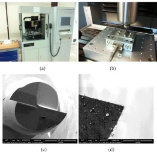
A three axis micro machining center (Mikrotools (DT-110), Figure 1(a) and 1(b)) is used in micro milling experiments. The machine has a range of (X,Y,Z) 200×100×100 mm, respectively. The accuracy of the machine is +/- 1 μm, with a resolution of 100 nm. The milling machine is equipped with an electric high speed spindle (Fischer Precise SC 3062, 10,000-60,000 rpm, 1.3 kW max. power, 25 Ncm max. torque). Flat micro end mills (NS tools, 2 teeth, 30° helix angle) made of fine grain (0.6 μm grain size) tungsten carbide are employed in micro machining tests. Figure 1(c) shows the scanning electron microscope image of the micro end mill. Cutting tool edge radius is measured to be around 2-3 μm (Fig. 1(d)). Micro machining forces are measured by Kistler mini dynamometer (9256C1, max 250 N) with its multichannel charge amplifier (Type 5080A) and transferred to a PC through a data acquisition card (National Instruments). All experiments are performed under dry machining conditions.
Tool wear is investigated using Keyence VHX 1000 digital microscope and surface roughness is investigated using Keyence VKX 110 3D laser surface topography device. The nominal tool diameter used in the experiments is 0.8 mm. The actual diameter of the end mills are smaller than the nominal diameter in order to compensate for possible run-out in the tool holder-spindle system.
(a) (b)
(c) (d)
Fig. 1. Experimental setup; (a) Micro machining center, (b) Mini dynamometer, (c) Micro end mill, (d) Cutting edge of the end mill.
The mold materials are expected to have good corrosion and wear resistance with good machinability. The mold material considered in this study is Stavax ESR (modified AISI 420 stainless steel) which is widely used in medical and optical industries. The work material used in machining experiments has hardness of 25 HRC. Table 1 shows the chemical composition of the material and Table 2 mechanical and thermal properties of the work material.
Table 1. Chemical composition of Stavax Typical Analysis % C Si Mn Cr V
0.38 0.9 0.5 13.6 0.3 Table 2. Mechanical Properties of Stavax Modulus of Elasticity (MPa) Thermal conductivity (W/mC) Specific Heat (J/kg C) 200000 16 460
3. Investigating the influence of process parameters In this study, plunging method, cutting speed, feed per
tooth, axial depth of cut and radial immersion are investigated as process parameters. Tool wear, surface roughness and milling forces were considered to evaluate the influence of machining parameters. Experimental investigations were performed during circular pocket milling operation which allows conducting uninterrupted micro milling experiments with longer tool path compared to slot milling operation. The diameter of the circular pocket is selected as 15 mm with 0.16 mm axial depth. Inside out spiral milling strategy was used and tool paths were generated using Cimatron E11 computer aided manufacturing software. Fig.2 shows the spiral tool path produced by the software. The natural frequency of the machine tool, mini-dynamometer, and workpiece assembly is identified as 1800Hz using impact hammer test.
Fig 2. CAM simulation of circular pocket milling operation.
3.1 Plunging Method
Three different plunging methods have been investigated while milling the circular pockets. The first plunging method is drilling with ramping, the second method is trochoidal tool path during entry, and the last method is pre-drilled hole. Trochoidal tool path has been found favorable in the literature for macro scale milling operations [14]. The micro milling operation is conducted under same process conditions where N=15000 rpm, feed rate is set as 120 mm/rev and depth of cut is set as 0.16 mm. In drilling with ramping plunging method, plunging feed rate and ramping angle was set as 3 mm/min and 2.5q, respectively. Trochoidal tool path was generated with pitch and radius settings 0.48 mm and 0.24 mm, respectively. Pre-drilled hole diameter is 1 mm. A total 12 pockets were machined for each condition and tool wear was recorded after each pocket. The milling forces were also measured at the final pocket. Fig. 3 shows the tool wear corresponding to each plunging method after 12 pockets.
(a)
(b)
(c)
Fig. 3 shows that cutting edges of the tool tips are chipped and rounded. A flank wear region due to abrasion can also be seen. Scanning electron microscope (SEM) image of the worn edge is shown in Fig. 4.
Fig. 4. SEM images of the wear zone on the tool.
In drilling with ramping and trochoidal path cases, tool wear region stretches to the tool center. Tool wear on the center of the tool is less for pre-drilled hole case. However, the edge chipping is similar in all cases. In order to observe the influence of plunging on the forces, milling forces were measured during machining of the final pocket. Milling forces in Fx, Fy, and Fz directions for pre-drilled hole method is shown in Fig 5. It must be noted that the variations in the direction of machining forces is due to circular tool path.
Fig 5 Milling forces for the case of pre-drilled hole.
Fig 6. Comparison of milling forces in z direction (top) pre-drilled hole, (middle) trochoidal, (bottom) drilling with ramping.
Fig. 6 shows that peak Fz forces in drilling with ramping are about 2.5 times higher than pre-drilled holes method. Trochoidal path milling forces in Fz direction are also lower than drilling with ramping method. It must be noted that the process parameters of drilling with ramping and trochoidal milling are not studied here. Larger forces in z direction due to flank wear is expected to affect surface quality.
3.2 Relationship between feed per tooth and radial immersion
The relationship between radial immersion and feed per tooth is important in terms of maintaining a balance between tool life and productivity during pocketing operations. In order to study this relationship, an experimental study was conducted. Cutting speed and axial depth of cut process parameters were fixed at 15000 rpm and 0.16 mm, respectively. Three levels for feed per tooth are selected as 2, 4 and 6 μm and three levels of radial immersion are selected as 20%, 60% and 80% of the tool diameter. Six pockets were machined using pre-drilled hole plunging method. Tool diameters were measured as process outputs after machining of each pocket. Table 3 shows the list of experimental conditions..
Table 3. Experimental conditions for investigating the relationship between radial immersion and feed (N=15000 rpm, ap=0.16 mm)
Exp. # Feed(μm) Radial Immersion (ae (%)) RI-1 2 0,2 RI-2 0,6 RI-3 0,8 RI-4 4 0,2 RI-5 0,6 RI-6 0,8 RI-7 6 0,2 RI-8 0,6 RI-9 0,8 RI-10 0,5 0,8
Fig 7 shows the cutting edges corresponding to the 1, RI-3, RI-4, and RI-7 experiments after machining 6 pockets with each tool.
(a) (b)
(c) (d)
Fig. 7. Comparison of cutting tool edges for a) Experiment #1, (b) Experiment #4, (c) Experiment #7, (d) Experiment #3
As tools wear out, their diameters reduce. Fig. 8 shows the relationship between feed per tooth and radial immersion where tool diameter values are monitored.
Fig 8. Tool diameter variation as a function of feed per tooth and radial immersion.
Low feed per tooth and low immersion resulted in the worst machining case. As feed per tooth value is increased, tool wear decreased as expected. For 60% radial immersion, similar tool performances were observed for all feed values. As for 80% radial immersion, tool performance peaked at 4 μm but then decreased at 6 μm feed per tooth. The results show that for each radial immersion there is a preferred feed value. It must be noted that tool run-out is also influential since it affects the chip load during milling.
3.3 Surface roughness
Surface roughness is the most important process output yet the most difficult to analyze in micro scale. In this study, a contactless method of surface roughness measurement method was used to analyze machined surfaces. Fig. 9 shows the laser scanning microscope used in this study and a sample of micro milled surface observed under the microscope. The microscope allows measurement of line roughness (e.g. Ra) and areal topography surface roughness (e.g. Sa) (ISO 25178) [15].
Fig. 9 Surface roughness measurement setup and surface of the micro milled circular pocket (x10 magnification).
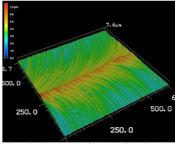
The area of observation of the microscope at the highest objective lens magnification is. Its vertical height display resolution is 5nm. In order to measure the surface roughness, a 7x5 matrix (each cell 135-100 μm) was defined on the surface using the microscope's software. Fig. 10 shows the stitched surface topography of the micro milled surface.
Fig 10. 3D surface topography of the micro milled surface (100X magnification).
Fig. 11 shows the areal surface roughness (Sa) measurements corresponding to experiments given in Table 3. The measurements are taken from the first machined pockets where the influence of tool wear is low. It is observed that low radial immersion experiments yield low surface roughness than high radial immersion tests. At high radial immersion, increasing feed yields better surface roughness. Based on our measurements, 20% radial immersion and 4 μm/tooth feed combination yielded the best areal surface roughness.
Fig 11. Surface roughness as a function of experimental conditions.
In micro milling, surface roughness is known to be stochastic due to process uncertainties and this stochastic behavior becomes more dominant as tool diameter decreases. In addition, powder-like chips observed while machining stainless steel get rubbed on the machined surface and hence degrade the quality of the surface [16]. The results of Experiment RI-10 reveals this situation, where a very low tool life (in Fig. 8) and a relatively poor surface finish (Fig. 11) was obtained.
3.4 Tool life
Tool life is an important information in terms of process parameters selection as it directly affects the economics of the process. Table 4 represents the experimental conditions (Taguchi-L9) used to investigate tool life of the micro end mill. Four parameters; cutting speed (N), feed per tooth (f),
700 705 710 715 720 725 730 735 740 745 0 2 4 6 8 Tool D iameter (m m )
Feed per Tooth (um)
20% 60% 80%
axial depth of cut (ap), and radial immersion (ae) are considered as process variables each with three levels. In addition, machining time per pocket and number of pockets machined with each tool are also given in Table 4.
Table 4. Experimental set for investigating tool life Exp
# N (rpm) f (μm) ap (μm) ae (%D) Time per pocket (sec) # of pockets S1 15000 2 80 0,4 228 9 S2 4 160 0,6 79 12 S3 6 320 0,8 41 15 S4 25000 2 160 0,8 74 5 S5 4 320 0,4 68 7 S6 6 80 0,6 31 14 S7 35000 2 320 0,6 68 7 S8 4 80 0,8 26 12 S9 6 160 0,4 32 10
After machining each pocket, micro end mills are investigated using digital microscope and the flank wear length and decrease in tool diameter values was measured. A flank wear limit of 30 μm and tool diameter reduction limit of 10% is used. Fig 12 shows the variation of tool life with respect to experimental cases shown in Table 4.
Fig. 12 Tool life variation with experiments
Due to limited recourses, only a single replicate of the experimental design given in Table 4 was conducted. Based on the results given in Fig. 12, the influence of cutting speed on the tool life can be clearly seen. In a recent study [17], it is shown that cutting speed is the main factor influencing the tool life followed by feed per tooth and depth of cut. Additional experimental study is required to reveal the relative importance of feed per tooth, axial depth of cut and radial immersion on the tool life.
4. Conclusion
The influence of process parameters is investigated and suitable process parameters for circular pocketing operation of Stavax stainless steel are identified. Experimental results show the influence of plunging method on tool wear which in turn affects micro milling forces and surface quality. The positive impact of not plunging the tool is also demonstrated. The relationship between radial immersion and feed per tooth is shown to affect tool wear. Areal surface roughness measurements revealed that low radial immersion yields lower surface roughness than high radial immersion tests. Small and discontinuous type of chips formed at very low
feeds is shown to have an adverse effect on surface roughness measurements.
Acknowledgements
The authors would like to thank The Scientific and Technological Research Council of Turkey (TÜBİTAK-110M660) and Ministry of Development of Turkey (HAMIT-Micro System Design and Manufacturing Research Center). The authors also thank Fevzi Yılmaz, Mustafa Kılıç and Muammer Kanlı for their help during experimental work.
References
[1] Dornfeld D, Min S, Takeuchi Y. Recent advances in mechanical micromachining. CIRP Ann-Manuf Techn 2006; 55; 745–768.
[2] Biermann D, Baschin A, Krebs E, Schlenker J. Manufacturing of Dies From Hardened Tool Steels by 3-axis Micromilling. Production Engineering Research and Development 2011; 5, 209-217.
[3] Filiz S, Conley C, Wasserman MB, Özdoğanlar OB. An Experimental Investigation of Micro-Machinability of Copper 101 Using Tungsten Carbide Micro-Endmills. Int. Journal of Machine Tools and Manufacture 2007; 47 7-8; 1088-1100.
[4] Lee K, Dornfeld DA. A study of Surface Roughness in the Micro-End-Milling Process, UC Berkeley: Laboratory for Manufacturing and Sustainability 2004.
[5] Natarajan U, Periyanan P, Yang S. Multiple-Response Optimization for Micro-Endmilling Process Using Response Surface Methodology. International Journal of Advanced Manufacturing Technology 2011; 56; 177-185.
[6] Rahman M, Kumar A, Prakash J, Micro Milling of Pure Copper, Journal of Materials Processing Technology. 2001; 116-1; 39-43.
[7] Uhlmann E, Piltz S, Schauer K. Micro Milling of Sintered Tungsten-Copper Composite Materials, Journal of Materials Processing Technology, 2005; 167 2-3; 402-407.
[8] Vazquez E, Rodriguez CA, Elias-Zuniga A, Ciurana J, An Experimental Analysis of Process Parameters to Manufacture Metallic Micro-Channels by Micro-Milling, International Journal of Advanced Manufacturing Technology 2010; 51; 945-955.
[9] Wang W, Kweon S, Yang S, A study on Roughness of the Micro-End-Milled Surface Produced by a Miniatured Machine Tool, Journal of Materials Processing Technology 2005 ;162-163; 702-708.
[10] Weinert K, Petzoldt V, Machining NiTi Micro-Parts by Micro-Milling, Materials Science and Engineering A, 2008; 672-675.
[11] Thepsonti T, Özel T. Multi-Objective Process Optimization for Micro-End Milling of Ti-6Al-4V Titanium Alloy, International Journal of Advanced Manufacturing Technology 2012; 63; 903-914.
[12]Li H, Lai X, Li C, Feng J, Ni J. Modelling and experimental analysis of the effects of tool wear, minimum chip thickness and micro tool geometry on the surface roughness in micro-end-milling. Journal of Micromechanics and Microengineering 2008; 18; 025006.
[13]Aramcharoen A, Mativenga PT, Yang S, Cooke KE, Teer DG, Evaluation and selection of hard coatings for micro milling of hardened tool steel. Int. Journal of Machine Tools and Manufacture. 2008; 48; 1578-1584. [14] Otkur M, Lazoglu I. Trochoidal milling. International Journal of Machine Tools and Manufacture. 2007; 47; 1324–1332.
[15] Introduction to Surface Roughness Measurement, Keyence Technical Document, http://www.keyence.com/products/microscope/laser-microscope/vk-x100_x200/
[16] Bisacco G, Hansen HN, De Chiffre L, Size Effects on Surface Generation in Micro Milling of Hardened Tool Steel. CIRP Annals - Manufacturing Technology. 2006; 55-1, 593–596.
[17] Saedon JB, Soo SL, Aspinwall DK, Barnacle A, Saad NH, Prediction and Optimization of Tool Life in Micromilling AISI D2 (~62 HRC) Hardened Steel. Procedia Engineering. 2012; 41, 1674 – 1683.
0 5 10 15 20 25 30 35 40 S1 S2 S3 S4 S5 S6 S7 S8 S9 To o l L if e ( m in ) Experiment #