c
T ¨UB˙ITAK
The Effect of phosphate Ions (PO
3
4
−
) on the Corrosion
of Iron in Sulphate Solutions
G. KILINC¸ C¸ EKER∗, B. YAZICI, M. ERB˙ILDepartment of Chemistry, C¸ ukurova University, Adana-TURKEY
H. GAL˙IP
Department of Chemistry, Eastern Mediterranean University, G. Ma˘gusa - T.R.N.C
Received 09.05.1997
The effect of phosphate ions on the corrosion of iron in sulphate solutions at different temperatures (293 K, 313 K, 333 K and 353 K) and at different pH (pH=2.1, 7.2 and 12.3) values was investigated. The electrochemical three-electrode technique was employed. The cathodic and anodic current-potential curves were obtained by strating from the corrosion potential measured against SCE and polarizing it first in cathodic and then in anodic direction. The results obtained indicate that at high pH (pH=7.2 and 12.3) SO24−+PO34−ions together reduce the corrosion rate of iron to a greater extent than SO24− alone. At low pH (pH=2.1), as the temperature increases the corrosion rate of iron increases in both SO24− and SO 2− 4 +PO 3− 4 solutions.
Introduction
Corrosion is the deterioration of a metal or its alloys by reaction with the environment. The type of metal, the composition of the surrrounding medium, the pH of the solution, whether the solution is aerated or deaerated, the solution temperature and the design effect are among the effective factors in corrosion. There
are different views regarding the effect of sulphate ions on the corrosion of various metal[1−3]. In general, the
sulphate ion has no effect on the corrosion of ferrous materials in neutral or close to neutral condition[4−5].
On the other hand, when pH<5 and temperature is constant, the sulphate ions increase the corrosion rate
of iron[6].
The materials which, when added to the corrosive medium in small amounts, reduce or stop the corrosion of metals are called inhibitors. The phosphates are one kind of inhibitor generally used, especially in water reservoirs and water distribution systems, cooling systems and power stations, in which inhibition polyhosphates such as trisodium phosphate sodium orthophosphate, sodium hexametaphosphate or even
phosphoric acid are used. The protective properties of phosphates depend on the pH of the medium.
Three different phosphate can be formed, depending on the pH of the medium (Na3PO4, Na2HPO4
and NaH2PO4), of which Na3PO4 is the most effective and NaH2PO4 is the least effective[7]. As the
concentration of phosphate ions increases, the inhibition effect increases[8]. Analyses made by electron
diffraction on corrosion products taken from the surface of the metal indicate that the phosphates enter the
structure of the surface films[8,9]. It is said that in basic solutions ( 8 <pH < 12 ) the phosphate ions form
the “Fe3(PO4)2” complex on the iron surface (whose solubility is very low), and thus the protective effect
is due to the formation of this complex[7−9].
Much research has been done on the inhibition effect of phosphates [9−15]. It is stated that these
materials are quite effective in cooling systems, and so they are widely used aginst corrosion in water cooling
systems[16−20]. The inhibition effect of the PO3−
4 ion in basic mediums is temperature-dependent, but
this temperature dependence is not so clear in the literature. However, its effects in an acidic medium are unknown in detail.
In this study, the effect of PO34− ion on the corrosion of ferrous materials in sulphate solutions was
studied at different temperatures (293 K, 313 K, 333 K and 353 K) and pH (2.1, 7.2 and 12.3) values. The effects of these ions on the corrosion of iron under these conditions, especially in an acidic medium, were determined.
Experimental
The electrochemical behaviour of iron was studied in electrolytes consisting of 0.1 M Na2SO4 and 0.1 M
Na3PO4+0.1 M Na2SO4 at
a) different temperatures ( 293 K, 313 K, 333 K and 353K), and b) different pH values (pH=2.1, 7.2 and 12.3)
The pH values of the solutions were adjusted by using H2SO4 and NaOH solutions. The temperature
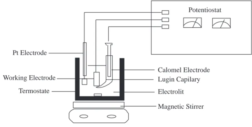
control was achieved by a thermostated cell. The experiments were carried out under atmospheric conditions, and the electrolyte was constantly stirred by magnetic stirrer at constant speed. The experimental set-up is shown in Figure 1. Potentiostat Calomel Electrode Lugin Capilary Electrolit Magnetic Stirrer Pt Electrode Working Electrode Termostate
Figure 1. Experimental Set-up
Iron (99.96 % Fe) coated with polyester and having a contact area of 2 cm2 was used as the working
electrode. A platinum foil with an area of 1 cm2 served as the auxilliary electrode, and the Standard
Calomel Electrode (SCE) was used as the reference electrode. The current-potential curves were obtained by the three-electrode technique. The electrode was first polarized in the cathodic and then in the anodic direction starting from the open circuit potential of iron measured against the calomel electrode and changing
the potential at a rate of 6 mV/min. The current-potential values were plotted for the interval -1.8 V — + 1.8 V. The current values measured were converted to current density values, and then semilogarithmic current density versus potential curves were plotted.
Experimental Results
The experimental results obtained by iron electode in different solutions and under varying conditions of temperature and pH are given in Figures 2-5 and in Tables 1-2. Figures 2-5 show the curves obtained at 293 K, 313 K, 333 K and 353 K, respectively. In these figures, a refers to pH=2.1 b refers to pH=7.2 and c refers to pH=12.3. The variation of the corrosion potentials of iron with the pH and temperature of the medium
in 0.1 M Na2SO4 and 0.1 M Na3PO4+0.1 M Na2SO4 solutions in given in Table 1. Table 1 indicates that
as the temperature increases, the corrosion potential shifts to more negative value for all solutions and pH values. However, at the same pH value and temperature, the corrosion potentials in sulphate solution were
more negative than those in SO24−+PO34−.
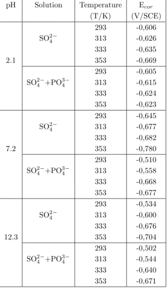
Table 1. The Corrosion Potentials (Ecor) of Iron Measured in Different Electrolytes at Different Temperatures and
pH values.
pH Solution Temperature Ecor
(T/K) (V/SCE) 293 -0,606 SO24− 313 -0,626 333 -0,635 2.1 353 -0,669 293 -0,605 SO24−+PO34− 313 -0,615 333 -0,624 353 -0,623 293 -0,645 SO24− 313 -0,677 333 -0,682 7.2 353 -0,780 293 -0,510 SO24−+PO34− 313 -0,558 333 -0,668 353 -0,677 293 -0,534 SO24− 313 -0,600 333 -0,676 12.3 353 -0,704 293 -0,502 SO24−+PO34− 313 -0,544 333 -0,640 353 -0,671
a) When pH=2.1
In all solutions, as the electrode is polarized towards negative potentials, the current densities increase
linearly up to ∼-0.900 V; but as more negative values are reached, the rate of increase of current density
starts to fall (Figures 2a-5a). In the cathodic region (Figure 2a-5a) at 293 K, while the current densities in phosphate solution are less than those in sulphate solution, at other temperatures the two ions show the same behaviour. _ _ _ _ _ _ _ _ _ _ _ _ _ 2.5 1.5 0.5 -0.5 -1.5 -2.5 -3.5 log i (mA.cm -2) 2000 1500 1000 500 0 Sulphate Sulphate+Phosphate -500 -1000 -1500 -2000 E(mV/SCE) Sulphate+Phosphate Sulphate+Phosphate Sulphate+Phosphate Sulphate+Phosphate log i (mA.cm -2) _ _ _ _ _ _ _ 2000 1500 1000 500 0 -500 -1000 -1500 -2000 E(mV/SCE) _ _ _ _ _ _ _ 2000 1500 1000 500 0 -500 -1000 -1500 -2000 E(mV/SCE) _ _ _ _ _ _ 2.5 1.5 0.5 -0.5 -1.5 -2.5 -3.5 log i (mA.cm -2) _ _ _ _ _ _ 2.5 1.5 0.5 -0.5 -1.5 -2.5 -3.5 (a) (b) (c)
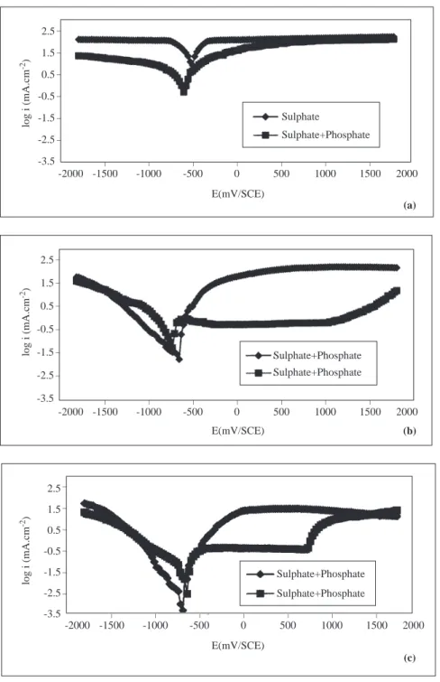
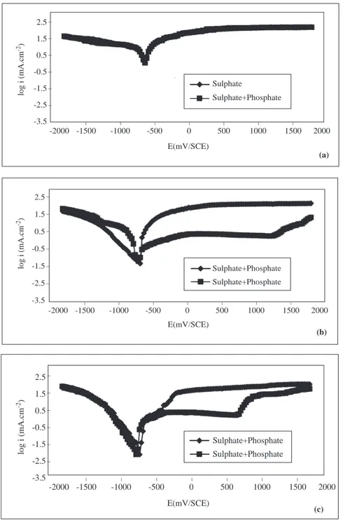
Figure 2. The Current Density-Potential Curves of Iron in 0.1 M Na2SO4 and in 0.1 M Na2SO4+Na3PO4
For example, at 293 K the change in current density with potential [∂i/∂E)T ,pH,c] in the linear portion is around 2803 mA/mV in sulphate solution, while it is 2056 mA/mV in phosphate solution. At 333 K, in the linear portion this change is the same in both sulphate and phosphate environments (3525 mA/mV). Starting from the open circuit potential, as one moves toward more positive potentials, except for the phosphate ion at 293 K, in all other electrolytes the current density increases linearly up to about 0.250 V, and the behaviour is similar in all electrolytes (Figures 2a-5a). At 293 K (Figure 2a) the linear increase in current density in
phosphate solution continues up to ∼-0.050 V, and around+ 0.900 V the sulphate and phosphate ions exert
the same behaviour. For example, at 293 K under anodic polarization, (∂i/∂E)T ,pH,c] in sulphate solution
is 2624 mA/mV, while it is around 1725 mA/mV in phosphate solution. But at other temperatures (313 K, 333 K and 353 K) these values are about the same in both sulphate and phosphate environments (5360 mA/mV).
b) When pH=7.2 and 12.3
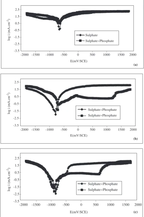
At different temperatures, when the electrode is polarized towards negative potentials the current densities increase in both sulphate and sulphate+ phosphate solutions (Figures 2b-5c). Under cathodic polarization at both pH values under constant temperature, the rate of increase of current density is greater in phosphate solutions than in sulphate solutions. For pH=7.2 and T=293 K, in the cathodic region while
the [∂i/∂E)T ,pH,c] is 1689 mA/mV in sulphate solution, it is 3426 mA/mV in phosphate solutions, and when
pH=12.3, this quantity is 2624 mA/mV in sulphate solition, and it is around 5607 mA/mV in phosphate solutions. The current densities under anodic poliraization conditions, however, are greater in sulphate
solutions than in phosphate solutions. When pH=7.2 and T=313 K, while the change in (∂i/∂E)T ,pH,c,
which is linear in sulphate solitions as from the corrosion potential, is around 2803 mA/mV, it is 1542 mA/mV in phosphate solutions (Figure 3b). When pH=12.3 and T=313 K, these values are 2418 mA/mV and 1186 mA/mV in sulphate and phosphate solutions, respectively (Figure 3c). In sulphate solutions, iron becomes passive at about -0.250 V, and this passivity is lost at more positive potentials (Figures 2b-5c). On
the other hand, in phosphate solutions, iron becomes passive in the potential interval ∼-0.500 V—∼+0.750
V at pH=12.3; and at ∼+ 1.250 V when pH=7.2. Under higher potentials, the passivity is lost (Figures
2b-5c). In the potential region where the passivity of iron is stable, the changes in current density with pH, type of ion and temperature are given in Table 2.
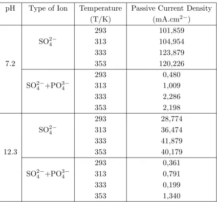
As seen in Table 2, in the potential intervals where iron is permanently passive, the current density decreases in both electrolytes at all temperatures as pH increases. Under the same temperature and pH conditions, the passive current density valuse of iron are smaller in phosphate solutions than in sulphate solutions. But in both electrolytes, as the temperature increases, the passive current density increases.
Discussion and Conclusion
As seen in reactions (1) and (2) below, depending on the pH of the solutions, the sulphate and phosphate ions are present in different proportions [20].
SO24−+ H2O *) HSO4−+ OH− Kd= 8, 33 . 10−13 (1)
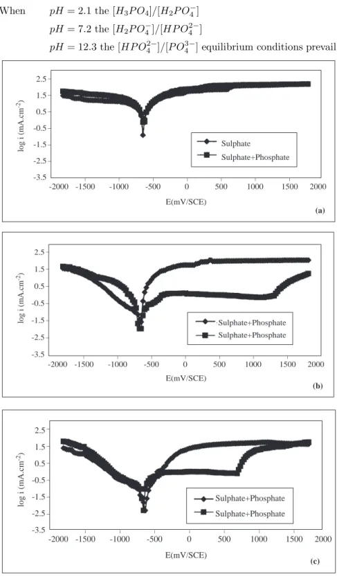
P O43−+ H2O *) HP O42−+ OH− Kd = 2, 08 . 10−2 (2) When the pH of the solution is increased from 2.1 to 12.3, according to equation (1), the concentration
of SO24− ion increases. The concentration of the phosphate ions in the medium accordingg to reaction (2) is
When pH = 2.1 the [H3P O4]/[H2P O−4]
pH = 7.2 the [H2P O−4]/[HP O 2− 4 ]
pH = 12.3 the [HP O42−]/[P O43−] equilibrium conditions prevail.
_ _ _ _ _ _ _ _ _ _ _ _ _ 2.5 1.5 0.5 -0.5 -1.5 -2.5 -3.5 log i (mA.cm -2) 2000 1500 1000 500 0 Sulphate -500 -1000 -1500 -2000 E(mV/SCE) Sulphate+Phosphate (a) (b) (c) Sulphate+Phosphate Sulphate+Phosphate _ _ _ _ _ _ _ 2000 1500 1000 500 0 -500 -1000 -1500 -2000 E(mV/SCE) log i (mA.cm -2) _ _ _ _ _ _ 2.5 1.5 0.5 -0.5 -1.5 -2.5 -3.5 Sulphate+Phosphate Sulphate+Phosphate log i (mA.cm -2) _ _ _ _ _ _ _ 2000 1500 1000 500 0 -500 -1000 -1500 -2000 E(mV/SCE) _ _ _ _ _ _ 2.5 1.5 0.5 -0.5 -1.5 -2.5 -3.5
Figure 3. The Current Density-Potential Curves of Iron in 0.1 M Na2SO4 and in 0.1 M Na2SO4+Na3PO4
Solutions at 313 K (a;pH=2.1, b; pH=7.2, c; pH=12.3).
When cathodic potential is applied to the systems in equilibrium, usually reduction of dissolved
(2H+2e*) H
2) takes place in acidic medium [15-18]. In this study, measurements were taken by polarizing
the electrode in both cathodic and anodic directions starting from the corrosion potential of the metal at
different temperatures (293 K, 313 K, 333K and 353 K) and pH (pH=2.1, 7.2 and 12.3) in SO24− and
SO24−+PO34− solutions. Under experimental conditions, when pH=2.1, the cathodic event must be mainly
the reduction of H+ ion (Figures 2a-5a). When pH=7.2 and 12.3 the expected reaction is the reduction of
the dissolved oxygen. However, the experimental results indicate that when pH >7 hydrogen reduction also takes place together with oxygen reduction. It is not only the limiting current of oxygen reduction that is present (Figures 2b-5c).
Table 2. The Passive Current Density of Iron.
pH Type of Ion Temperature Passive Current Density
(T/K) (mA.cm2−) 293 101,859 SO24− 313 104,954 333 123,879 7.2 353 120,226 293 0,480 SO24−+PO34− 313 1,009 333 2,286 353 2,198 293 28,774 SO24− 313 36,474 333 41,879 12.3 353 40,179 293 0,361 SO24−+PO34− 313 0,791 333 0,199 353 1,340
It is stated in the literature that when pH>7, the hydrogen ions to be reduced are produced by the decomposition of water [18]. When reactions (1) and (2) reach equilibrium on a metal surface, the hydrogen ions which will be left free as a result of a change in pH and which will take part in the reduction reaction, are formed on the surface, and thus hydrogen ions ready to be reduced are present on the surface of the metal. The cathodic current-potential curves do not exhibit the characteristic limiting current of oxygen reduction, nor do they indicate any limitations related to hydrogen ion reduction. This fact supports the view than the
H+ ions are first formed on the surface in a stepwise manner and then take part in the reduction reaction. If
this is so, the pH of the metal surface has to be lower than the pH of the solution. This view is in agreement with the literature [18].
When the equilibrium constants of reaction (1) and (2) are compared, if reaction (1) reaches equilib-rium rather than reaction (2), it is clear that the pH of the surface will be lower. Lower surface pH enhances the hydrogen ion reduction and increases the rate. This is the reason that the experimentally determined
(∂i/∂E)T ,pH,c values are greater in SO24− solution (Figures 2a-5c).
The results obtained under anodic polarization indicate that at high pH (pH=7.2 and 12.3) iron becomes passive but at low pH(pH=2.1) it undergoes corrosion (Figures 2-5). When pH=7.2 and 12.3, the
surface together with OH− ions [7,15-18]. Under all temperatures when pH is raised from 7.2 to 12.3, the decrease in passive current density and the shifting of open circuit potentials to more positive values support these views (Tables 1 and 2).
_ _ _ _ _ _ _ _ _ _ _ _ _ 2.5 1.5 0.5 -0.5 -1.5 -2.5 -3.5 log i (mA.cm -2) 2000 1500 1000 500 0 Sulphate -500 -1000 -1500 -2000 E(mV/SCE) Sulphate+Phosphate (a) (b) (c) _ _ _ _ _ _ _ 2000 1500 1000 500 0 -500 -1000 -1500 -2000 E(mV/SCE) log i (mA.cm -2) _ _ _ _ _ _ 2.5 1.5 0.5 -0.5 -1.5 -2.5 -3.5 Sulphate+Phosphate Sulphate+Phosphate log i (mA.cm -2) _ _ _ _ _ _ _ 2000 1500 1000 500 0 -500 -1000 -1500 -2000 E(mV/SCE) _ _ _ _ _ _ 2.5 1.5 0.5 -0.5 -1.5 -2.5 -3.5 Sulphate+Phosphate Sulphate+Phosphate
Figure 4. The Current Density-Potential Curves of Iron in 0.1 M Na2SO4 and in 0.1 M Na2SO4+Na3PO4
Solutions at 333 K (a;pH=2.1, b; pH=7.2, c; pH=12.3)
Under the same temperature and at the same pH, a comaparison of the lower value of passive current
density in PO34− solutions with that in SO24− solutions shows that the PO34− ions are adsorbed to the metal
pH(7 <pH <12) it is said that the layer forming on the metal surface is of the Fe3(PO4)2 type and that this layer coating the surface of metal improves the protection [7-10, 13, 14,19]. The protection effect increases
also as the pH of the solution increases, showing that the formation of Fe(OH)3 on the metal surface plays
a role as well. On the other hand, in both phosphate and sulphate solutions, as the temperature increases, the passive current densities increase.
_ _ _ _ _ _ _ _ _ _ _ _ _ 2.5 1.5 0.5 -0.5 -1.5 -2.5 -3.5 log i (mA.cm -2) 2000 1500 1000 500 0 Sulphate -500 -1000 -1500 -2000 E(mV/SCE) Sulphate+Phosphate (a) (c) _ _ _ _ _ _ _ 2000 1500 1000 500 0 -500 -1000 -1500 -2000 E(mV/SCE) log i (mA.cm -2) _ _ _ _ _ _ 2.5 1.5 0.5 -0.5 -1.5 -2.5 -3.5 Sulphate+Phosphate Sulphate+Phosphate (b) Sulphate+Phosphate Sulphate+Phosphate log i (mA.cm -2) _ _ _ _ _ _ _ 2000 1500 1000 500 0 -500 -1000 -1500 -2000 E(mV/SCE) _ _ _ _ _ _ 2.5 1.5 0.5 -0.5 -1.5 -2.5 -3.5
Figure 5. The Current Density-Potential Curves of Iron in 0.1 M Na2SO4 and in 0.1 M Na2SO4+Na3PO4
Solutions at 353 K (a;pH=2.1, b; pH=7.2, c; pH=12.3).
This shows that as the temperature increases, the stability of the complex compound formed on the electrode surface decreases (Table 2). Only the structure of the complex forming on the iron surface is given in
literature, and nothing is mentioned in relation to its stability. The separation of this complex from the metal surface as the temperature increases (293 K, 313 K, 333 K and 353 K) shows that the solubility of the complex increases with temperature. At low pH (pH=2.1), the iron surface undergoes corrosion; this must be due to the fact that the surface is always bare (Figures 2a-5a). Because protection is related to the stability of the complex, at low pH the decomposition of this complex causes corrosion of iron. By using these ions, applications for protection can only be tried at low temperatures and high pH (7.2<pH <12.3).
In conclusion, SO24− and PO34− ions, at pH=7.2 and 12.3, passivate iron and reduce its corrosion
rate. The passivation process is brought about by the formation of a protective, sparingly soluble complex
compound on the surface of iron by phosphate ions. When only SO24− ions are present in the solution, it is
harder for iron to become passive.
At low pH (pH=2.1), and as temperature increases (293 K, 313 K, 333 K and 353 K), the corrosion rate of iron increases in both types of solution.
References
1. M. Erbil., Krozyon ˙Inhibit¨orleri, SEGEM, Ankara, (1984).
2. I. L. Rozenfeld, corrosion Inhibitors, McGraw-Hill Inc. USA, (1981).
3. D. Geana, A. A. El Miligy, W. J. Lorenz, J. appl. Electrochem., 4, 337-345 (1974). 4. H. P. Leckie, and H. H. Uhling, J. Electrochem. Soc., 12, 1262-1267 (1966). 5. M. Erbil and W. J. Lorenz, Werkst. Korros., 29 505-510, (1978).
6. H. Galip and M. Erbil, Do˘ga-Tr. J. of Chemistry, 16, 2682-72 (1992).
7. R. N. Parkins, N. J. Holroyd and R. R. Fessler, Corros.-NACE, 34, 253-261, (1978). 8. R. B. Rebak and J. R. Galvele, Corros. Sci., 29, 1003-1018, (1989).
9. K. Kurusawa and T. Fukushima, Corros. Sci., 29, 1103-1114, (1989).
10. B. Hakansson, P. -E. Augustsson and G. G. Vannerberg Electrochim. Acta., 28, 791-799, (1983). 11. J. Flis Corros.-NACE, 40, 232-239 (1984).
12. L. Marahusin, S. Kokot and D. P. Schweinsberg, Corros. Sci., 34, 1007-1016, (1993). 13. M. Ergun and A. Y. Turan, Corros. Sci., 32, 1137-1142, (1991).
14. F. Zucchi and G. Trabenelli, Corros. Sci., 11 141-151, (1971).
15. J. O. M. Bockris and A. K. N. Reddy, Modern Electrochemistry, Vol 2, Plenum Press, New York (1977). 16. K. J. Vetter, Electrochemical Kinetics, Academic Press, New York (1967).
17. P. Lorbeer and W. J. Lorenz, Electrochim. Acta,25, 375-381 (1980).
18. M. A. Morsi, Y. A. Elewady, P. Lorbeer and W. J. Lorenz, Werkst. Korros. 31, 108-114, (1980). 19. G. H. Awad and T. P. Hoar, Corros. Sci., 15 581-588, (1975).