376 IEEE JOURNAL OF SELECTED TOPICS IN QUANTUM ELECTRONICS, VOL. 16, NO. 2, MARCH/APRIL 2010
A Planar Metamaterial With Dual-Band
Double-Negative Response at EHF
T. Funda G¨undo˘gdu, Kaan G¨uven, Mutlu G¨okkavas, Costas M. Soukoulis, and Ekmel ¨
Ozbay
Abstract—We report the fabrication and electromagnetic
char-acterization of a planar composite metamaterial (CMM) that is designed to achieve dual-frequency double-negative response at the lower end of the extremely high-frequency (EHF) band. The CMM is based on cut wire pairs and continuous wire elements. Dual-frequency operation is obtained by employing cut wire pairs of two different lengths within the unit cell of the CMM. The magnetic response of the cut wire pairs and the left-handed trans-mission band of the CMM are demonstrated by experiment and numerical simulations. It is found that the combined electric re-sponse of the dual-band CMM is complicated and imposes certain restrictions to the structure design in achieving true left-handed response at both designated frequencies.
Index Terms—Electromagnetic propagation, metamaterial,
neg-ative refractive index.
I. INTRODUCTION
M
ETAMATERIALS are artificial structures that respond to the incident electromagnetic wave with tailored ef-fective permittivity and permeability functions. A particular class of metamaterials has electromagnetically resonant ele-ments that provide negative permittivity and permeability re-sponse, and thus comprise an effective medium with negative refractive index [1]. Frequently used element designs are pe-riodic wires for negative permittivity (ε < 0), and split-ring resonators and cut wire pairs for negative permeability (µ < 0) response [2], [3]. Due to these two distinct components, these designs are also called composite metamaterials (CMMs). The majority of the metamaterial studies focused on achieving the desired electromagnetic response at a single frequency band. Dual- or multifrequency response is reported at microwave us-ing S-shaped resonators [4], and omega-shaped resonators [5], Manuscript received June 9, 2009; revised July 17, 2009. First published October 2, 2009; current version published April 7, 2010. This work was supported by the European Union under projects EU-METAMORPHOSE, EU-PHOREMOST, EU-PHOME, and EU-ECONAM, and TUBITAK under the Project 105E066, Project 105A005, Project 106E198, and Project 106A017. The work of K. G¨uven was supported by GEBIP program of Turkish Academy of Sciences.T. F. G¨undo˘gdu is with the Found. for Research and Tech. Hellas, GR-700 13 Heraklion, Greece, and also with Nanotechnology Research Center, Bilkent University Ankara, Turkey (e-mail: [email protected]).
K. G¨uven is with the Physics Department, Koc University, 34450 Istanbul, Turkey (e-mail: [email protected]).
M. Gokkavas is with the Nanotechnology Research Center, Bilkent Univer-sity, 06800 Ankara, Turkey (e-mail: [email protected]).
C. M. Soukoulis is with the Iowa State University, Ames, IA 50011 USA (e-mail: [email protected]).
E. ¨Ozbay is with the Physics Department, Nanotechnology Research Center, Bilkent University, 06800 Ankara, Turkey (e-mail: [email protected]).
Color versions of one or more of the figures in this paper are available online at http://ieeexplore.ieee.org.
Digital Object Identifier 10.1109/JSTQE.2009.2031618
at near-infrared [6], [7] and terahertz regimes [8], [9]. The multi-band operation may be derived from a single-multi-band CMM struc-ture by superposition principle, but the combined electric and magnetic response in a multiband CMM design can differ sig-nificantly from that of the individual responses of its constituent elements. Therefore, investigating the electromagnetic response of the dual structure in detail can elucidate design considerations in order to improve their utilization in multiband applications.
In this paper, we report the design, fabrication, and experi-mental/simulated characterization of a dual-band CMM aimed to operate at the lower part of the extremely high-frequency (EHF) band. The CMM exhibits double negative (i.e., simulta-neously ε < 0 and µ < 0) at both its designated frequencies. Section II describes the design and fabrication of the CMM. The simulated and measured transmission spectra of the metamate-rial are presented in Section III. The measured phase advance through the CMM is given in Section IV.
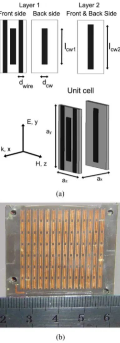
II. DUAL-BANDCUTWIREPAIR ANDWIREMETAMATERIAL The metamaterial consists of dielectric layers that are pat-terned with an array of metal cut wire and continuous wire elements on either side. The dielectric layers are then stacked periodically to form a 1-D metamaterial [10], [11]. For prop-agation normal to the layer plane, the electric field vector is parallel to the cut wires and the magnetic field vector is per-pendicular to the plane between the cut wire pairs (see Fig. 1). In this propagation direction, the electric field induces a plasma resonance on both cut wire pairs and continuous wires. Conse-quently, the dielectric response of the medium below the plasma cutoff frequency becomes negative below the plasma frequency
ε(ω) = 1−ω 2 p ω2 ω 2 p = 2πc2 d2ln(2d/w l) (1) where d is the separation between the wires, w is the width of wires, and c is the speed of light in the dielectric/air medium. This plasma frequency changes significantly in the presence of cut wires in the CMM.
The magnetic field induces an inductive–capacitive resonance on the cut wire pairs. The resonance frequency ωm depends on the geometrical parameters (in particular, the length) of the cut wire pairs and the dielectric constant of the separating layer. For a detailed formulation of this dependence, see [3] and [10]. The overall magnetic response can be represented through an effective permeability µeff = 1− F ω2 m ω2− ω2 m + iωΓ . (2) 1077-260X/$26.00 © 2009 IEEE
FUNDA G ¨UNDO ˘GDU et al.: PLANAR METAMATERIAL WITH DUAL-BAND DOUBLE-NEGATIVE RESPONSE AT EHF 377
Fig. 1. (a) Schematic view of the dual-band metamaterial unit cell. (b) Sample photograph of the first layer showing array of cut wires and wires. The scale numbers are in centimeters.
TABLE I
METAMATERIALDESIGNPARAMETERS
For dual-band operation, the unit cell is designed to accom-modate two cut wire pairs of different length. The unit cell consists of two layers, each containing one cut wire pair. The continuous wires are located in one of the layers. Fig. 1 shows the schematic of the unit cell and a photograph of first layer. The geometrical parameters are given in Table I.
The cut wire and wire patterns are fabricated by chemical etching the thin copper layer on both sides of the dielectric layer. In addition, several layers are fabricated that do not include continuous wires so that the isolated response of the cut wire pairs can be investigated.
Fig. 2. Simulated transmission spectra of dual-band cutwire-pairs with one (top dashed line) and two (middle solid line) unit cells. The transmission of the electrically shorted cutwire-pair is given for comparison (bottom solid line).
It may be possible to design a truly modular structure where the operation frequencies of the metamaterial can be changed simply by inserting or extracting different cut wire pair lay-ers. However, the nontrivial electric response of the CMM im-poses certain restrictions on the design parameters in achieving double-negative response.
III. SIMULATEDTRANSMISSION OF THEDUAL-MODECMM The simulated transmission spectra are obtained by using a commercial EM-solver software. The simulation employs elec-tric and magnetic boundary conditions on the unit cell along the
y- and z-directions (see Fig. 1).
Fig. 2 shows the transmission spectrum of the dual cut wire pair medium containing one and two unit cells, respectively, in
x-direction. The continuous wires are not present in this
struc-ture. The resonances occur at 28.2, 35.0, and 42.3 GHz. In order to exploit the origin of the resonance, the cut wire pairs are elec-trically shorted at their long ends. This removes the capacitive coupling at the ends, and hence, the magnetic coupling, but the electric coupling remains. The transmission spectrum of shorted cut wire pairs (black curve) clearly indicates that the first two resonances are of magnetic origin, whereas the resonance at 42.3 GHz is due to electric coupling. The suppression of the transmission thereafter in the two-unit-cell structure is associ-ated with the photonic bandgap effects induced by the stacking periodicity [12].
The transmission spectrum of the dual-band CMM for one unit cell is shown in Fig. 3 (squares) with the cut wire pair spectrum (triangles). The CMM has three transmission peaks slightly shifted from the respective resonance dips of the cut wire pair. The shift occurs in the magnetic resonance frequency due to the presence of continuous wires. In order to identify the transmission peaks, a control specimen for the CMM is constructed by using cut wire pairs electrically shorted at their long ends. This shorted CMM exhibits only one transmission
378 IEEE JOURNAL OF SELECTED TOPICS IN QUANTUM ELECTRONICS, VOL. 16, NO. 2, MARCH/APRIL 2010
Fig. 3. Simulated transmission spectra of the CMM (squares) and the CMM with shorted cutwire-pairs (solid curve). The spectrum of cutwire-pair from Fig. 2 is included for comparison (triangles).
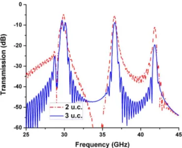
Fig. 4. Simulated transmission spectra of the CMM containing two (dashed line) and three (solid line) unit cells.
peak in common with that of the normal CMM [13]. Note that this peak is also common with the weak transmission peak of the cut wires at ∼41.0 GHz. By virtue of these results, the CMM comprises a double-negative (ε < 0, µ < 0) medium at its transmission bands around 28.2 and 35.0 GHz, and a positive (ε > 0, µ > 0) medium at∼41 GHz.
Fig. 4 shows the transmission spectra of the CMM structures containing two and three unit cells, respectively. With increasing CMM thickness (i.e., number of layers), the transmission bands become relatively pronounced by the strong suppression of the background. The suppression originates from the loss inherent to the resonance (in particular, to the imaginary part of the dielectric permittivity).
Fig 5. Measured transmission spectra of dual-band cut wire structure contain-ing (top curve) one and (bottom curve) two unit cells.
IV. EXPERIMENTALMEASUREMENTS OF THE DUAL-BANDCMM
A. Transmission Spectrum
The measurement setup consists of an HP 8510C network an-alyzer and two horn antennas. Transmission measurements are performed in free space. In Fig. 5, the transmission of the dual-band cut wire pair is shown. The resonances occur at 30, 36, and 40.5 GHz. The electric resonance shows a slight shift for the two-unit-cell structure that is caused by the nonuniformity of the spacing of thin dielectric layers. The two-unit-cell structure ex-hibits the photonic bandgap effect next to the electric resonance in agreement with the simulations. The dependence of this gap on the spacing of layers will be discussed elsewhere [12].
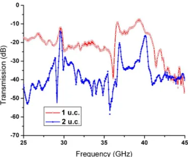
Fig. 6 shows the measured transmission spectra of the dual-band CMM with one and two unit cells. In agreement with the simulations (see Figs. 3 and 4), the transmission bands are obtained. The background suppression is also observed experi-mentally with increasing number of unit cells. Experiment data indicate that the misalignment between the layers affects the transmission level significantly.
B. Phase Spectra
We finally commence an analysis of the phase delay through the CMM with successive increasing number of unit cells. It is known that the phase advance is negative in a (ε < 0 and µ < 0) medium [14]. Thus, increasing the number of layers should decrease the phase dispersion at the transmission bands where the medium is double negative. Fig. 7 shows the phase dispersion for the CMM structures containing two, three, and four unit cells, respectively. The inset shows the behavior in the first (30 GHz) transmission band, and the main figure shows the behavior at the second (36 GHz) and third (40.5 GHz) transmission bands. Evidently, there is a crossover between the second and third transmission bands where the ordering of the dispersion curves
FUNDA G ¨UNDO ˘GDU et al.: PLANAR METAMATERIAL WITH DUAL-BAND DOUBLE-NEGATIVE RESPONSE AT EHF 379
Fig 6. Measured transmission spectra of the CMM containing (top curve) one and (bottom curve) two unit cells.
Fig. 7. Measured phase spectra of CMM structures containing two, three, and four layers of unit cell. Note the crossover of the phase dispersion curves before the last transmission band at∼40 GHz.
is reversed. We observe that with increasing thickness of the CMM, the phase delay decreases (in magnitude) in the first and second bands, whereas it increases in the third band.
V. CONCLUSION
In this study, we present an experimental realization of a dual-band CMM at EHF frequencies. We have found that although the dual operation can be based on a straightforward extension of single-band structures, the multilayer design of the CMM results in a nontrivial electric response, which must be taken
into account to attain a proper double-negative (ε < 0 and µ < 0) medium response. Well-defined transmission bands are obtained with “thin” CMM structures containing few number of unit cells. When compared with in-plane propagating metamaterials [4], [5], the normal-to-plane propagation provides full beam coverage within a single layer. Some modularity is available in comparison to integrated “fishnet”-type structures reported in [7]–[9].
ACKNOWLEDGMENT
The authors thank K. B. Alici for fabrication of samples. REFERENCES
[1] D. R. Smith, W. J. Padilla, D. C. Vier, S. C. Nemat-Nasser, and S. Schultz, “Composite medium with simultaneously negative permeability and per-mittivity,” Phys. Rev. Lett., vol. 84, pp. 4184–4187, 2000.
[2] J. B. Pendry, A. J. Holden, W. J. Stewart, and I. Youngs, “Extremely low frequency plasmons in metallic mesostructures,” Phys. Rev. Lett., vol. 76, pp. 4773–4776, 1996.
[3] J. B. Pendry, A. J. Holden, D. J. Robbins, and W. J. Stewart, “Magnetism from conductors and enhanced nonlinear phenomena,” IEEE Trans.
Mi-crow. Theory Tech., vol. 47, no. 11, pp. 2075–2084, Nov. 1999.
[4] H. Chen, L. Ran, J. Huangfu, X. Zhang, K. Chen, T. M. Grzegorcyzk, and J. A. Kong, “Metamaterial exhibiting left-handed properties over multiple frequency bands,” J. Appl. Phys., vol. 96, pp. 5338–5340, 2004. [5] K. Aydin, Z. Li, M. Hudlicka, S. A. Tretyakov, and E. Ozbay,
“Transmis-sion characteristics of bianisotropic metamaterials based on omega shaped metallic inclusions,” New J. Phys., vol. 9, pp. 326–336, 2007.
[6] D. Kwon, D. H. Werner, A. V. Kildishev, and V. M. Shalaev, “Near-infrared metamaterials with dual-band negative-index characteristics,” Opt. Exp., vol. 15, pp. 1647–1652, 2007.
[7] U. K. Chettiar, A. V. Kildishev, H. Yuan, W. Cai, S. Xiao, V. P. Drachev, and V. M. Shalaev, “Dual-band negative index metamaterial: Double negative at 813 nm and single negative at 772 nm,” Opt. Lett., vol. 32, pp. 1671– 1673, 2007.
[8] Y. Yuan, C. Bingham, T. Tyler, S. Palit, T. H. Hand, W. J. Padilla, D. R. Smith, N. M. Jokerst, and S. A. Cummer, “Dual-band planar electric metamaterial in the terahertz regime,” Opt. Exp., vol. 16, pp. 9746–9752, 2008.
[9] M. Li, Z. Wen, J. Fu, X. Fang, Y. Dai, R. Liu, X. Han, and X. Qiu, “Composite metamaterials with dual-band magnetic resonances in the terahertz frequency regime,” J. Phys. D, vol. 42, pp. 115420-1–115420-4, 2009.
[10] J. Zhou, L. Zhang, G. Tuttle, T. Koschny, and C. M. Soukoulis, “Negative index materials using simple short wire pairs,” Phys. Rev. B, vol. 73, pp. 041101-1–041101-4, 2006.
[11] K. Guven, D. Caliskan, and E. Ozbay, “Experimental observation of left-handed transmission in a bilayer metamaterial under normal-to-plane propagation,” Opt. Exp., vol. 14, pp. 8685–8693, 2006.
[12] T. F. Gundogdu, M. Gokkavas, K. Guven, Z. Li, and E. Ozbay, “Electric response in planar metamaterials,” submitted for publication.
[13] K. Aydin, K. Guven, M. Kafesaki, L. Zhang, C. M. Soukoulis, and E. Ozbay, “Experimental observation of true left-handed transmission peak in metamaterials,” Opt. Lett., vol. 26, pp. 2623–2625, 2004. [14] K. Aydin, K. Guven, C. M. Soukoulis, and E. Ozbay, “Observation of
neg-ative refraction and negneg-ative phase velocity in left-handed metamaterials,”
Appl. Phys. Lett., vol. 86, pp. 124102-1–124102-3, 2005.