B- TEORİK BİLİMLER
Eskişehir Technical University Journal of Science and Technology B- Theoritical Sciences 2018, Volume:6 - pp. 57 - 66, DOI: 10.20290/aubtdb.492147
4th INTERNATIONAL CONFERENCE ON EARTHQUAKE ENGINEERING AND SEISMOLOGY
CONTRIBUTION OF GRAVITY FRAMES TO SEISMIC PERFORMANCE OF STEEL MOMENT RESISTING FRAMES
Mustafa ZORLU 1, *, Bülent AKBAŞ 1, J. Jay SHEN 2, Onur ŞEKER 3
1
Department of Civil Engineering, Gebze Technical University, Gebze-Kocaeli 2
Department of Civil, Construction and Environmental Engineering, Iowa State University, USA 3
Department of Civil Engineering, MEF University, İstanbul
ABSTRACT
Traditionally, lateral stiffness and strength of the gravity frames in steel buildings are neglected in structural analysis. During the past earthquakes, such as Northridge, USA, 1994 and Kobe, Japan, 1995, unexpected failures were detected at beam-to-column connections of steel moment resisting frames (MRFs). In the aftermath of these earthquakes, extensive research has been carried out to reveal the causes of these failures. Based on the detailed observations, it is likely that the reserve capacity provided by the gravity frames prevented the highly damaged steel buildings from collapsing, since majority of the moment-resisting connections failed prematurely during the Northridge earthquake (1994). Even though the influence of gravity frames (GFs) on structural behavior can be substantial, little attention is paid to evaluate its impact on structural response. With this paper, the contribution of interior GFs in seismic performance of special moment resisting steel frames (SMRFs) is evaluated. For this purpose, 4- and 9-story SMRFs were designed in accordance with the requirements of Draft Turkish Seismic Code (2016). The frames are, then, subjected to incremental dynamic analysis. To evaluate the contribution of the interior GFs on the overall seismic performance of structural system, inelastic behavior of shear tab (simple) connections at beam-to-gravity-only columns were idealized as semi-rigid joints. A general purpose structural analysis software, ETABS, is utilized for the analyses. The results of the study are presented in terms of story drifts, base shear vs. roof displacement.
Keywords: Gravity-only frames, Steel moment frames, Seismic design
1.INTRODUCTION
In the current design practice, it is typical to separate the gravity load-carrying and Lateral Force Resisting Systems (LFRS) for an economical design of steel buildings. LFRS are, in general, arranged on the perimeter of a building while interior frames comprise Gravity Frames (GF), which are responsible for withstanding vertical loads. Traditionally in steel buildings, strength and lateral stiffness of the gravity columns, which incorporate shear connections are neglected in structural analysis. However, ignoring the reserve capacity provided by the gravity frames without properly quantifying its actual influence on the behavior may be deceptive when assessing structural performance of steel buildings with perimeter frames. Comprehensive observations after the past earthquakes, indicate that the effect of the gravity columns on overall structural performance can be substantial. For instance, majority of the pre-Northridge moment connections experienced brittle fractures during the 1994 Norhtridge and 1995 Kobe earthquakes but still none of the steel structures collapsed partially or entirely (FEMA 267, 1995). This was attributed to the impact of the reserve capacity provided by GFs (FEMA 267, 1995; Lui and Astaneh-Asl 2000). Subsequent to unveiling the potential significance of the gravity columns, recent research showed that bending moment transferred from beam to column through shear connections, depending on the composite action, may reach 20% to 40% of the beam’s plastic moment capacity (Lui and Astaneh-Asl 2000; 2004). It is, in fact, revealed that shear connections act as semi-rigid (SR) connections rather than pin connections (Lui and Astaneh-Asl, 2000; 2004). Although the
cyclic behavior of shear connections is thoroughly investigated and the moment-rotation relationship is well-established by experimental studies (Lui and Astaneh-Asl, 2000; 2004), the influence of gravity frames on the seismic behavior of steel buildings in the regions with high seismicity has yet to be adequately evaluated. Survey of the limited research conducted on the gravity frame effect can be found in Flores et al. (2012).
This paper focuses on the contribution of gravity frames to seismic performance of steel buildings that conventionally designed to resist seismic loads solely by special moment resisting frames (SMRFs). For this purpose, low-rise and mid-rise steel buildings are designed in accordance with the current design codes (TSC, 2016; AISC360, 2010). Then, the seismic behavior of the SMRFs with and without considering the contribution of gravity frames. The influence of the gravity frames is evaluated in terms of drift, roof displacement and rotational demands through Incremental Dynamic Analysis (IDA). Finally, conclusions are drawn to extend our understanding of the actual behavior of steel buildings with perimeter SMRFs.
2. STRUCTURAL MODELS
2.1. Design of Low-Rise (4-Story) and Medium-Rise (9-Story) SMFRs
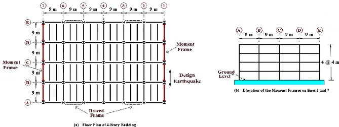
Typical low-rise (4-story) and medium-rise (9-story) buildings with steel moment frames, as shown in Figures 1 and 2, were designed considering the design requirements of Draft Turkish Seismic Code-2016 (TSC, Code-2016) and the provisions of AISC 360 (2010). These buildings are similar with the ones that were developed during the FEMA-sponsored steel frame research programs performed subsequent to 1994 Northridge earthquake (FEMA 355, 2000). The base plans of the buildings are symmetrical. As shown in Figure 1, the plan dimensions of four-story building is 54.0 m by 36.0 m with 6×9-m spans and 4×9-m spans in two perpendicular directions, respectively, with a typical 4-m story height. The columns are fixed at the base level.
Figure 1. 4-story frame - plan (a) and elevation (b)
Similarly, the nine-story building has 5×9-m spans in both perpendicular directions with plan dimensions of 45.0 m by 45.0 m. This building has a basement floor (B1 level in Figure 2b) in contrary to 4-story building. The typical story height is 4 m whereas the ground level and basement level has 5.40-m and 3.60-m, respectively (Figure 2b). The columns are considered as pinned connected to the foundation at the basement level. For the 9- story building, basement walls are assumed to prevent horizontal displacement at the ground level, therefore the ground level is assumed as the seismic base.
Figure 2. 9-story frame - plan (a) and elevation (b)
For each building, the structural system is consisted of perimeter SMRFs and interior simply connected GFs; that is, seismic loads are merely endured by two SMRFs arranged on the perimeter as shown in Figure 1(a) & Figure 2(a) and the interior GFs are not explicitly designed to resist lateral loads arise due to seismic actions and are not included in the analysis.
The buildings were assumed to be located at high seismic area which are designed for a site in the main
campus of Gebze Technical University, where short period (Ss) and long period (S1) map spectral
acceleration coefficients are 1.58g and 0.82g, respectively (identified on the web site of Boğaziçi Observatory and Earthquake Research Institute). Site class ‘ZB’ is considered in design (TSC, 2016). The SMRFs were designed using structural system behavior factor of R=8 and overstrength factor of
D=3. In addition to the beam and column element self-masses, super-dead load of 5.0 kN/m2 and live
load of 3.0 kN/m2 (4,0 kN/m2
& 1,0 kN/m2 for the roof), respectively, were used in design. The
TSC-2016 design base shear forces corresponding to the 4-story and 9-story structures were determined as 5875 kN and 6306 kN, respectively, based on the Modal Response Spectrum Method. As expected, drift requirement governed the design for both buildings. The beam and column elements are made of
European I-Sections steel with a yield strength of Fy = 345 MPa. The final member sizes were selected
considering the seismic design requirements stipulated in AISC 341 and are summarized in Table 1. Braced frames, shown in Figures 1 and 2, are used as the seismic force resisting system in the direction perpendicular to the moment frames.
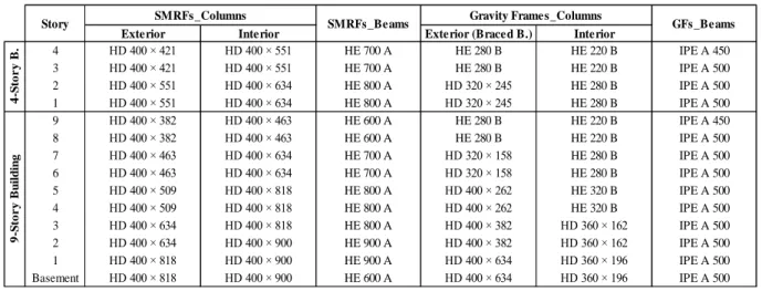
Table 1. Beam and Column Member Sizes in SMRFs and GFs
Exterior Interior Exterior (Braced B.) Interior
4 HD 400 × 421 HD 400 × 551 HE 700 A HE 280 B HE 220 B IPE A 450 3 HD 400 × 421 HD 400 × 551 HE 700 A HE 280 B HE 220 B IPE A 500 2 HD 400 × 551 HD 400 × 634 HE 800 A HD 320 × 245 HE 280 B IPE A 500 1 HD 400 × 551 HD 400 × 634 HE 800 A HD 320 × 245 HE 280 B IPE A 500 9 HD 400 × 382 HD 400 × 463 HE 600 A HE 280 B HE 220 B IPE A 450 8 HD 400 × 382 HD 400 × 463 HE 600 A HE 280 B HE 220 B IPE A 500 7 HD 400 × 463 HD 400 × 634 HE 700 A HD 320 × 158 HE 280 B IPE A 500 6 HD 400 × 463 HD 400 × 634 HE 700 A HD 320 × 158 HE 280 B IPE A 500 5 HD 400 × 509 HD 400 × 818 HE 800 A HD 400 × 262 HE 320 B IPE A 500 4 HD 400 × 509 HD 400 × 818 HE 800 A HD 400 × 262 HE 320 B IPE A 500 3 HD 400 × 634 HD 400 × 818 HE 800 A HD 400 × 382 HD 360 × 162 IPE A 500 2 HD 400 × 634 HD 400 × 900 HE 900 A HD 400 × 382 HD 360 × 162 IPE A 500 1 HD 400 × 818 HD 400 × 900 HE 900 A HD 400 × 634 HD 360 × 196 IPE A 500 9 -S to r y Bu il d in g
Story SMRFs_Columns SMRFs_Beams Gravity Frames_Columns GFs_Beams
4 -S to r y B.
2.2. Beam-to-Column Connections in SMFRs and GFs
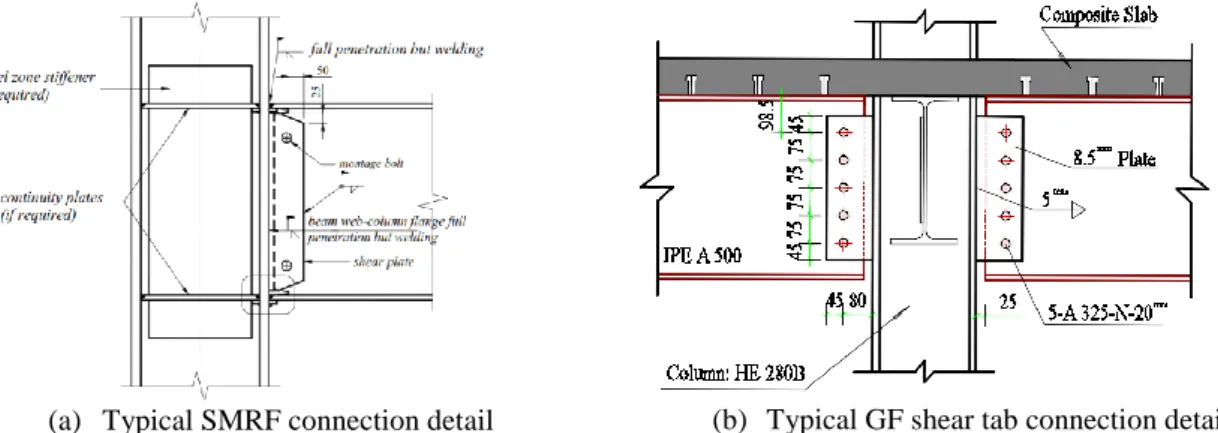
Typical beam-to-column connection details for moment resisting frames were identified in Annex 9B of Draft TSC (2016). In this study ‘Full Penetration Welded Joint’ connection detail, as described under item 9B.4 of TSC (2016), has been considered as the typical beam-to-column assembly for the whole SMRFs’ connections. Figure 3(a) indicates the application boundaries of the aforesaid typical connection detail.
(a) Typical SMRF connection detail (b) Typical GF shear tab connection detail Figure 3. Typical SMRF (a) and GF (b) systems beam-to-column connection details
The simple beam-to-column connections in GFs were designed as single-plate 390mm×125mm×8.5mm
implemented to the beam webs using five bolts and welded to the column flange with a single plate
using 5mm fillet weld on both sides, as shown in Figure 3(b).
Three analytical models (Case A, B and C) were compared in order to investigate the contribution of the interior GFs in seismic performance of SMRFs. Case-A model represented the typical analytical model, in which the contribution of the GFs is not included in the model. On the other hand, the connections in GFs were considered as semi-rigid moment connections in Case-B and Case-C models. Case B is modeled as bare steel frame while the composite deck effect on M-θ relationship of shear connections is considered in Case-C. P-Delta effects are taken into account for all cases. The details of numerical modeling of the three cases are described in the following section.
2.3. Special Moment Resisting Frame Elements’ (Nonlinear Behavior) Model
Nonlinear modeling parameters described in Table 9-6 of ASCE 41 (2013) were adopted for the moment connections in SMRFs. Figure 4(a) presents the force-deformation relationship used for the beam and
beam-column elements. Relevant a, b and c values corresponding to Q-θ relation are taken as 9θy, 11θy
and 0.6, respectively.
IO ≤ 1θy
LS ≤ 6θy
CP ≤ 9θy
(b) Software Input Data of SMRF Elements’ Nonlinear Hinge Model
Figure 4(b) represents the typical nonlinear parameters modelling input data of beam-columns. Note that the strain hardening is assumed to be zero. Acceptance criteria for IO, LS and CP were implemented
as 1θy, 6θy and 9θy, respectively, in accordance with the limits prescribed in TSC (2016).
2.4. Gravity System Beam-to-Column Connections’ Model
For the composite beam-to-column connections, analytical model proposed by Shen et al. [6, 9] and Wen et al. [7], is used in this study (Case-C model). Mathematical model for simplified shear connection (Case-B model) [9], is also included for the purpose of comparison. In Case-B, connections in GFs were idealized by semi-rigid connection model with a rotational stiffness of 10% of (4EI/L) and a flexural
strength of 20% (Mp) of the connecting beams’ (IPE A 500) plastic moment capacity. Figure 5(b) shows
the details of the GFs connection models in Case-B and Case-C. It is explicit in Case-B model that the positive bending strength is overestimated by neglecting composite action whereas the negative bending strength is overestimated, as shown in Figure 5(b).
(a) Idealized GF Joint Connection Model (b) Connections’ M-θ relation models in GFs [9] Figure 5. Case-B and Case-C connection models in GFs
2.5. Modelling Assumptions
3D modeling of 4-Story and 9-Story buildings are shown in Figure 6. There were two SMRFs in both buildings whereas five and four GFs existed in the direction of excitation, respectively, for 4- and 9-story buildings. The plastic hinges were assigned at the column face in SMRFs. As described in section 2.3, material non-linearity is incorporated in the models through nonlinear hinge models, which are assigned to beam and beam-column elements in SMRFs as (M3) and (P-M3) hinges, respectively.
(a) 4-story building 3D model (b) 9-story building 3D model Figure 6. 3D Software Models of 4-story (a) and 9-story (b) buildings (for Case-A)
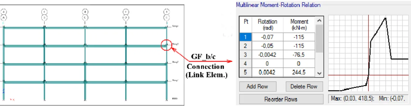
Concrete deck is assumed to be rigid. In Case-A, shear connections were modeled as pin connections. However, in Case-B and Case-C models, these connections were rectified in compliance with the prescribed connection models as identified in item 2.4 above. To represent the true behavior of the
Figure 7. GF beam-to-column connection model using Link Elements (i.e. Case-C Model)
3. NONLINEAR DYNAMIC ANALYSIS PROCEDURE
3.1. Earthquake Ground Motion (GM)
The ground motion (GM) acceleration record of 1999 Kocaeli earthquake (recorded at Düzce) was selected in order to initially investigate the 4-Story and 9-Story buildings. Details of GM record and the corresponding Response Spectrum (with %5 damping) is shown in Figure 8 below. For the GM, the
peak ground acceleration (PGA0) is equal to 0.31 g.
(a) GM Record (1999 Kocaeli_Düzce Record) (b) Response Spectrum of GM (%5)
Figure 8. Ground Motion Time History (a) and Response Spectrum (b), PGA = 0,31g
3.2. Nonlinear Incremental Dynamic Analysis (IDA)
The Incremental Dynamic Analysis (IDA) approach is utilized to investigate the seismic responses in regards of story drifts and base shear vs. roof displacement. The ever-increasing intensities of the GM is applied to the 3D models (for Case-A, B & C models) until reaching an interstory drift angle of 0.10 radians. Each time history analysis was carried out using non-linear direct integration method available in ETABS.
The fundamental periods of the 4-story buildings are 1.14 s, 1.12 s and 1.09 s, respectively, for models Case-A, B and C. For the cases in the 9-story buildings, the fundamental periods were obtained as 2.44 s, 2.40 s and 2.33 s. Note that the influence of the GFs on the initial stiffness of the buildings was noticeable. Due to the substantial difference in fundamental periods between the 4-story and 9-story buildings, increment sizes in different ranges were utilized. The spectral accelerations were increased by 0.10g and 0.05g increments for the 4-story and 9-story structures, respectively. The scale factor (SF) is determined in such a way that the ground motion intensity with a scale factor of SF would have a
spectral acceleration, Sa, equal to (SF) g. To exemplify, a scale factor of 1.0 corresponds to 1.0 g spectral
4. RESULTS AND DISCUSSION
Figure 9 plots the IDA curves of 4- and 9-story buildings, relating peak story drift ratios obtained from the frames to the “first-mode” spectral accelerations. It seems that the impact of GFs became more substantial for both 4-and 9-story buildings, as the intensity of the GMs increases. It is also noteworthy that 4-story buildings followed a similar trend while the response obtained from Case C of 9-story buildings differ from other two cases after a story drift ratio of 4%. This can be attributable to unsymmetrical hysteretic behavior of shear connections combined with higher-mode effects. The 4,7%
design drift ratio is reached approximately at spectral accelerations, Sa, of 1.0 g/1.05 g/1.15 g and 0.70
g/0.75 g/0.80 g, respectively, for Case-A, B and C of the 4-story and 9-story frames.
Figure 9. Peak Drift Ratio development of the 4-story (a) and 9-story (b) structures under GM
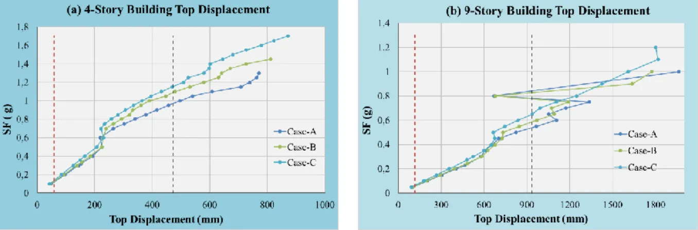
Similar to Figure 9, Figure 10 plots the peak roof displacements obtained under various GM intensities. The 4-story and 9-story frames reach their design roof displacement of 474 mm and 936 mm,
respectively, approximately at spectral accelerations, Sa, of 0.95 g/1.10 g/1.15 g and 0.55 g/0.60 g/0.70
g, respectively, for Case-A, B and C.
Figure 10. Top Displacement development of the 4-story (a) and 9-story (b) structures under GM
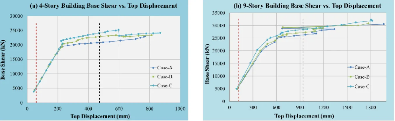
In Figure 11, base shear forces versus roof displacements curves are plotted for each analysis. As noted, base shear forces corresponding to abovementioned design roof displacements were obtained as 20751 kN/22942 kN/24080 kN and 26375 kN/27311 kN/28597 kN, respectively, for 4-story and 9-story building models. Note that the design base shear forces for 4- and 9-story buildings have been identified previously as 5875 kN and 6306 kN, respectively.
interior GFs to the overall seismic performance of the structural system become noticeable in 4-story building, in which the near collapse behavior was prevented. Furthermore, in 9-story building models, contribution of the GFs was apparent at SF=0.75 g. However, it was significant at SF=1.0 g, as seen in Figure 15.
Figure 11. Base Shear Force vs. Top Displacement relation of the 4-story (a) and 9-story (b) structures
Hinge rotations representing the IO, LS and CP performance levels are figured as; IO≤1θy<LS≤6θy<CP≤
9θy, as described in item 2.3 above.
(a) Case-A (b) Case-B (c) Case-C Figure 12. Hinge Formation of 4-story SMRF at SF=1,15 g
(a) Case-A (b) Case-B (c) Case-C Figure 13. Hinge Formation of 9-story SMRF at SF=0,75 g
Figure 14 plots the peak story drift ratio distributions along the building elevations for each structures when the scale factors were, SF=1.15 g and SF=0.75 g, respectively.
Finally, the maximum rotational demand corresponding to these SFs on beam-to-column connections of SMRFs were examined and found to be 0.041 rad/0.036 rad/0.031 rad and 0.045 rad/0.039 rad/0.035 rad., respectively, for the 4-story (story level 1) and 9-story (story level 2) buildings analysis models (Case-A, B & C).
Figure 14. Drift Ratio distributions along 4-story (a) and 9-story (b) buildings’ height
(a) Case-A (b) Case-B (c) Case-C Figure 15. Hinge Formation of 9-story SMRF at SF=1,0 g
5. CONCLUSION
Typical buildings (4- and 9-story) with SMRFs were designed in compliance with the requirements of Draft Turkish Seismic Code-2016, and subjected to ground motion record in order to investigate the contribution of the GFs to the overall performance of the lateral load resisting system. The goal was to assess whether or not the additional stiffness and strength provided by the GFs will contribute to the performance of the SMRFs. The resulting seismic responses were presented in regards of peak drift ratio, top displacement and base shear versus top displacement, and the primary outcomes are noted as below;
(1) The lower and upper bound of design drift ratio, as per TSC-2016, were identified as 2,35% and 4,7%. The 4- and 9-story buildings were designed considering the upper bound of drift ratio as 4,7%. Ground motion intensities fulfilling the design drift ratio were noted as maximum as SF=1,15 g and SF=0,75 g, respectively, in Case-C models of the 4- and 9-story buildings, in which the contribution of composite slab were included in the numerical models.
(2) Considering the all the response indicators used to evaluate the performance, such as GM spectral
acceleration intensity, Sa and the base shear forces corresponding to the peak roof displacement, it
can be concluded that the response of the GFs with bare shear tab beam-to-column connections (Case-B) and GFs beam-to-column connections with the composite concrete slab (Case C) were %7 and %15 larger than that of the conventional SMRF models, respectively.
(3) It is apparent that including the contribution of GFs in numerical models improved the overall performance of the steel buildings, especially when composite slab was involved. However, further investigation is needed to improve the assessment.
REFERENCES
[1] TSC 2016, Draft Turkish Seismic Code for Buildings, Turkey Federal Emergency Management
Agency (AFAD), Ankara, 2016.
[2] AISC 360, Specification for Structural Steel Buildings, AISC 360–10, American Institute of Steel
Construction Inc, Chicago, IL, 2010.
[3] ASCE 7, Minimum Design Loads for Buildings and Other Structures, ASCE 7–10, American
Society of Civil Engineers, Virginia, 2010.
[4] ASCE/SEI 41, Seismic Evaluation and Retrofit of Existing Buildings, ASCE/SEI 41-13,
American Society of Civil Engineers, Virginia, 2013.
[5] Shen J, Sabol TA, Akbas B, Sutchiewcharn N, Seismic Demand on Column Splices in Steel
Moment Frames, Engineering Journal Fourth Quarter (2010) 223.
[6] Shen J, Carter C, Akbas B, Sutchiewcharn N, Wen R, Seismic performance evaluation of braced
frames with and without design ductility, Technical Report Submitted to American Institute of Steel Construction, 2012.
[7] Wen R, Akbas B, Shen J, Practical moment-rotation relations of steel shear tab connections, J.
Constr. Steel Res. 88 (2013) 296–308.
[8] Wen R, Akbas B, Sutchiewcharn N, Shen J, Inelastic behaviors of steel shear tab connections,
Struct. Des. Tall Special Build. 23 (2014) 929–946.
[9] Shen J, Wen R, Akbas B, Seker O, Uckan E, Near-collapse behavior of steel buildings with
non-ductile concentrically braced frames, connections, J. Constr. Steel Res. 113 (2015) 101-114. [10] Shen J, Wen R, Akbas B, Doran B, Uckan E, Seismic Demand on brace-intersected beams in
two-story two-story X-braced frames, Engineering Structures 76 (2014) 295-312.
[11] Flores FX, Jarrett JA, Charney FA, The Influence of Gravity-Only Framing on the Performance of Steel Moment Frames, 15 WCEE LISSOA (2012).
[12] Vamvatsikos D, Cornell CA, The Incremental Dynamic Analysis and Its Application to
Performance-Based Earthquake Engineering, 12th Europ. Conf. on Earthquake Engineering Paper Ref. 479.
[13] ETABS (2016), Integrated Building Design Software, version 16.1.0, Computers and Structures, Berkeley, CA.
[14] Lui J, Astaneh-Asl A. Cyclic testing of simple connections including effects of slab. Journal of Structural Engineering 2000; 126(1):32–39. DOI: 10.1061/(ASCE)0733-9445(2000)126:1(32). [15] Lui Judy and Abolhassan Astaneh-Asl. "Moment-rotation parameters for composite shear tab
connections." Journal of Structural Engineering 130.9 (2004): 1371-1380.
[16] FEMA. (2000). “FEMA 355C: State of the Art Report on Systems Performance of Steel Moment Frames Subject to Earthquake Ground Motion Shaking.” H. Krawinkler, ed., Federal Emergency Management Agency, Washington, D.C.