MEF UNIVERSITY
MECHANICAL DESIGN AND FLUID ANALYSIS OF A
VERTICAL-AXIS WIND TURBINE
"TRIBINE"
Mechanical Engineering Senior Design Project
Alp İğertokoğlu, Büşra Koç, Cankat Enver Süren
3
MEF UNIVERSITY FACULTY OF ENGINEERING
DEPARTMENT OF MECHANICAL ENGINEERING
MECHANICAL DESIGN AND FLUID ANALYSIS OF A
VERTICAL-AXIS WIND TURBINE
"TRIBINE"
Mechanical Engineering Senior Design Project
Alp İğertokoğlu, Büşra Koç, Cankat Enver Süren
Advisor: Prof. Dr. Dante Dorantes, Assist. Prof. Ehsan Layegh Khavidaki
ISTANBUL, 2018
4
MEF UNIVERSITY
FACULTY OF ENGINEERINGDEPARTMENT OF MECHANICAL ENGINEERING
Name of the project: Mechanical Design And Fluid Analysis of a Vertical-Axis Wind Turbine "Tribine"
Name/Last Name of the Student: Alp, İğertokoğlu, Büşra Koç, Cankat Enver Süren Date of Presentation: 04/01/2018
We hereby certify that the design project titled ‘Design and Construction of a Vertical-Axis Wind Turbine’ by Alp, İğertokoğlu, Büşra Koç, Cankat Enver Süren has been completed under our supervision.
04/06/2018
Prof. Dr. Dante Dorantes
Assist. Prof. Ehsan Layegh Khavidaki
ACADEMIC HONESTY PLEDGE
In keeping with MEF University Student Code of Conduct, we pledge that we have completed this work on our own and that we have not received any inappropriate assistance in its preparation.
We further declare that all reference sources in print or on the web are explicitly cited in this report.
NAME DATE SIGNATURE Alp İğertokoğlu 07/06/2018
Büşra Koç 07/06/2018 Cankat Enver Süren 07/06/2018
5
ABSTRACT
MECHANICAL DESIGN AND FLUID ANALYSIS OF A VERTICAL-AXIS WIND TURBINE "TRIBINE"
Alp İğertokoğlu, Büşra Koç, Cankat Enver Süren
Faculty of Engineering
Department of Mechanical Engineering
Advisors: Prof. Dr. Dante Dorantes, Assist. Prof. Ehsan Layegh Khavidaki
JUNE 2018, 65PAGES
Purpose of the final project is to design a wind turbine with an artistic view, choose proper wind turbine axis and comparison of them. The chosen wind turbine should be manufacturable, eco friendly and innovative. After the wind turbine blade selection, flow simulations were done by Solidworks.
Keywords: Wind Turbine, Innovative, Renewable Energy, CAD Design, Motor
6
ÖZET
DİKEY EKSENLİ “TRIBINE” RÜZGAR TÜRBİNİ MEKANİK TASARIMI VE AKIŞKAN ANALİZİ
Alp İğertokoğlu, Büşra Koç, Cankat Enver Süren Mühendislik Fakültesi
Makine Mühendisliği Bölümü
Tez Danışmanları: Prof. Dr. Dante Dorantes & Assist. Prof. Ehsan Layegh Khavidaki HAZİRAN, 2018, 65 SAYFA
Bu projenin amacı, yenilikçi, düşük maliyetli ve düşey eksenli rüzgâr türbini geliştirmek, analizlerini yapmak ve üretmektir. Piyasada birçok rüzgâr türbini bulunmaktadır. Projede ön plana çıkan kriterler; doğa dostu, yenilikçi, üretilebilir ve şehir içinde kullanılabilir bir rüzgâr türbini olmasıdır. “Tribine” adını taşıyan tasarımımız, düşey eksenli olmakta ve bu sayede hem düşük rüzgâr hızlarında çalışabilmekte hem şehir içinde kullanılabilmekte hem de düşük gürültü seviyesinde çalışmaktadır. Akışkan analizi Solidworks ile yapılmıştır.
Anahtar Kelimeler: Rüzgâr Türbini, Yenilikçi, Yenilenebilir Enerji, Bilgisayar
7 TABLE OF CONTENTS ABSTRACT 5 ÖZET 6 LIST OF TABLES 9 LIST OF FIGURES 10 LIST OF ABBREVIATIONS 11 1. INTRODUCTION 12 1.1. Motivation 12 1.2. Broad Impact 12
1.2.1. Global and Environmental Impact 13
1.2.2. Legal Impact 13
2. PROJECT DESCRIPTION AND PLANNING 15
2.1. Project Description 15
2.2. Project Planning 15
2.2.1 Aim of the Project 15
2.2.2 Project Coverage 15
2.2.3 Success Criteria 16
2.2.4. Project Time and Resource Estimation 17 2.2.5. Solution Strategies and Applicable Methods 17
2.2.6. Risk Analysis 17
2.2.7. Tools Need 18
3. PROBLEM DEFINITION AND SYNTHESIS 18
3.1. Problem Definition 18
3.2. Synthesis 19
4. Turkish Design and Installation Standards/Restrictions of VAWT 25 5. MODELLING, ANALYSIS, TESTING AND OPTIMIZATION 31
5.1. Design Specifications 31
5.2. Motor Selection 32
5.2.1. Differences between traditional DC vs AC motors 34 5.2.2. AC, DC & BLDC Motor Characteristics 34
5.3. Computer-aided Design Modelling 35
5.4. Simulation 37
5.4.1. Fixed Blade Feasibility Test 37
5.4.2. Tests on Three Bladed Turbine 38
5.4.3. Frequency Simulations 41
8
5.5. Cost Analysis 43
5.6. Testing 46
5.6.1. Test on Printed Three Bladed Models 47 5.6.2. Tips for 3D Printing & Analysis 49
5.7. Optimization 50
6. DESIGN, IMPLEMENTATION AND RESULTS 51
6.1. Design 51
6.2. Implementation 52
6.3. Electrical Layout 53
7. CONCLUSION 54
7.1. Lifelong Learning 54
7.2. Professional and Ethical Responsibilities of Engineers 55
7.3. Contemporary Issues 55
7.4. Teamwork 56
APPENDIX 56
ACKNOWLEDGEMENT 58
9
LIST OF TABLES
● Table 1 - Comparison of HAWT & VAWT● Table 2 - Comparison of different types of wind turbines ● Table 3 - Comparison of Airfoils
● Table 4 - Comparison of AC Induction & BLDC Motors
● Table 5 - Results of The GOE 448 No Overlap Ratio with Different Angles
● Table 6 - Results of The GOE 448 With Overlap Ratio with Different Angles
● Table 7 - Frequency Responses ● Table 8 - Comparison of Motors ● Table 9 - Comparison of Batteries
● Table 10 - Economic Comparison of DC Motors
● Table 11 - Detailed Cost Calculation
● Table 12 - Experiment conducted to test the efficiency of the number of blades ● Table 13 - Test on Printed Three Bladed Test Results
10
LIST OF FIGURES
● Figure 1- Renewable Energy
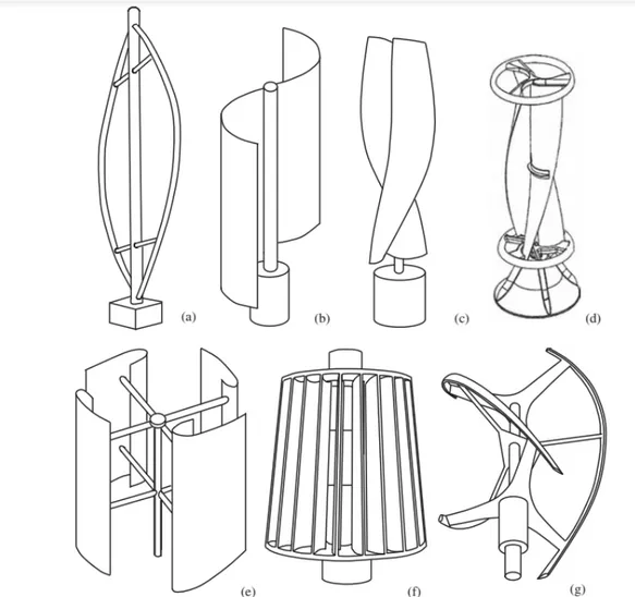
● Figure 2 - Gantt Chart of the Project ● Figure 3 - Power Curve Graph ● Figure 4 -Types of VAWT ● Figure 5- Parameters of Savonius ● Figure 6- Design Method for Turbines ● Figure 7 - Building Procedure
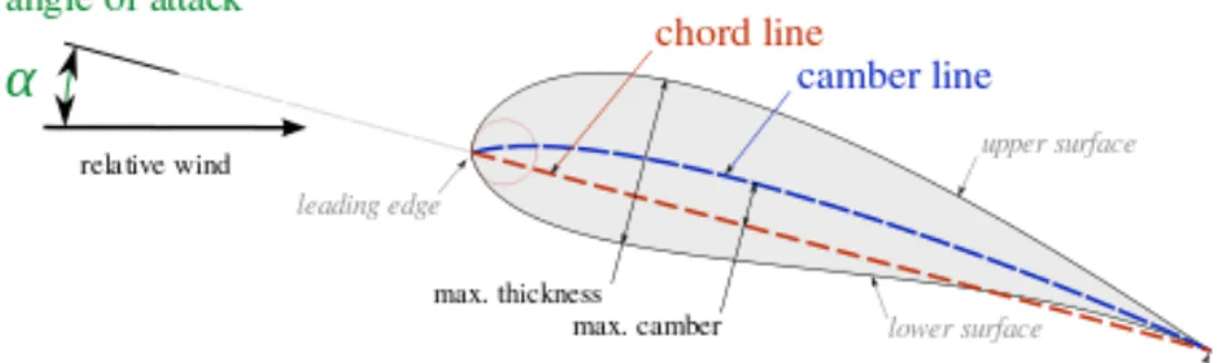
● Figure 8 - Airfoil Specifications
● Figure 9 - Effects of Different Overlap Ratios & Ratio Formula Representation ● Figure 10 - Optimum Overlap Ratios
● Figure 11 - Wind Turbine Induction Generator ● Figure 12 - DC & AC Characteristics
● Figure 13 - BLDC Characteristic
● Figure 14 - First CAD model for 2 & 3 Blades
● Figure 15 - GOE 448 Three Blade New CAD Models
● Figure 16 - Two Different options for open shaft GOE 462 Airfoil ● Figure 17- One Blade Feasibility Test
● Figure 18 - Flow Trajectories on a Single Blade ● Figure 19 - Flow Simulation on Three Blade Model ● Figure 20 - GOE 448 No-Overlap Ratio Angles vs Forces ● Figure 21 - GOE 448 With Overlap Ratio Angles vs Forces ● Figure 22 - Natural Frequency Response Results
● Figure 23 - Frequency Simulation Results for Different Mode Shapes ● Figure 24 - Test Setup & Tachometer
● Figure 25 - First Printed Prototype ● Figure 26 - Two Blade Paper Model
● Figure 27 - 3 Blade and DNA Type Paper Model ● Figure 28 - Three Blade of 3D Printed Model ● Figure 29 - Two Blade of 3D Printed Model
● Figure 30 - Top View of Two Blade 3D Printed Model ● Figure 31 - Charge Controller
● Figure A1 - First Dough Models
● Figure A2 - Combination of Savonius & Darrieus Wind Turbines ● Figure A3 - Ducted Type Wind Turbine
11
LIST OF ABBREVIATIONS
VAWT Vertical Axis Wind Turbine
HAWT Horizontal Axis Wind Turbine
DC Direct Current
BLDC Brushless Direct Current
AC Alternative Current
A Ampere
V Voltage
RPM Rotation Per Minute
CAD Computer Aided Design
12
1. INTRODUCTION
The purpose of this Senior Design Project is to choose the exact blade type for vertical axis wind turbines, compare with the other blades, make the flow simulation of proper blade type with fully defined design on Solidworks, finding proper overlap ratio, manufacturing samples and test them.
1.1. Motivation
The motivation is to design a sustainable wind turbine which can generate electricity. Unfortunately, there is no comparison table or report that published. We are aiming to make the comparison of standard blade type for vertical axis. We realized that there is no such a comparison for vertical axis turbines.
1.2. Broad Impact
There are lots of greenhouse gases effects and carbon emission due to consuming petroleum or natural gases. These effects cause harmful damages for environment. On the other hand, petroleum and natural gas reserves decrease faster. For those reasons, alternative energy usage must be grow up. For the next years, solar and wind energy will be pioneer energy sources. (Reuters, 2016) The wind energy or solar energy may be expensive source but in long term, benefits will be understood.
If the natural energy sources which are thermal and photovoltaic solar energy, wind power, surface and deep geothermal heat, hydroelectricity obtained through dams and small rivers and biomass do not combined intelligently, the consuming of natural gas or fossil fuel cannot be determined. The figure (Piccard, 2017) below shows us that the expanding alternative energy sources creates new employment areas.
Figure 1. Renewable Energy
On the other hand, the renewable energy methods are criticized with their unreality and unreliability. But nowadays, storage the energy and using it is possible. In 2013, Better Place,
13
an Israeli start-up had managed to raise $1 billion and was supposedly going to change the world. It is an example for it. The other example can be Tesla. “In 2015, they launched Powerwall, a home battery with a 7-kWh energy storage capacity, sufficient to power most homes during the evening using electricity generated by solar panels or the utility grid during the day. Not to mention their famous electric cars, with a range of 400 km, where a recharge of only 20 minutes already allows the car to drive 200 km or so.” (Piccard, 2017).
Davos World Economic Forum 2017 session opened with a restating of the 2015 Paris Agreement created to mitigate climate change by reducing greenhouse gas (GHG) emissions. Energy production and consumption comprise two-thirds of the world’s GHG emissions, and the panelists discussed several steps to meet the goals outlined in the agreement (Lau, 2017).
● Enacting carbon pricing, which was notably missing from the agreement ● Constructing infrastructure to support existing renewables
● Developing better means of energy storage
● Continuing technological exploration and research on renewables
Al Gore ‘Former Vice President of the United States’ gave a speech about renewable energies and he defends his ideas in politic areas he said; ‘We have such fuels. Scientists have confirmed that enough solar energy falls on the surface of the earth every 40 minutes to meet 100 percent of the entire world's energy needs for a full year. Tapping just a small portion of this solar energy could provide all of the electricity America uses and enough wind power blows through the Midwest corridor every day to also meet 100 percent of US electricity demand. Geothermal energy, similarly, is capable of providing enormous supplies of electricity for America.’ According to his speech in future we better use solar and wind energy instead of such fuel sources (Al Gore, 2008).
1.2.1. Global and Environmental Impact
Renewable technologies are considered as clean sources of energy and optimal use of these resources minimize environmental impacts, produce minimum secondary wastes and are sustainable based on current and future economic and social societal needs. The broad education is necessary to understand the impact of engineering solutions in a global, economic, environmental, and societal context. (Marjolein, 2015) For making the world better place people must decrease consumption of natural sources and start to find how to figure out to produce energies with renewable energy sources. The wind energy or solar energy may be expensive source today, but in long term, benefits will be understood, and they will become prevalent. Also, generally these sources don’t harm other living creatures and the world can live longer for creatures.
1.2.2. Legal Impact
After economic and environmental issues are defined, the design of a system should be decided. It should be an innovative design, components should be efficient and strong enough to afford predicted failure rate, to make this happen clean room technology systems will be used during this process. The design should have realistic constraints such as economic, environmental, social, political, health and safety, manufacturability, and sustainability
14
Environmental friendly, the design is made for fighting environmental problems such as energy consumption. The design should not harm environment and people during working. The design must consider environmental problems. When the design causes problems, those problems will create health and social issues. Turbines must be designed to eliminate social and environmental issues such as noise pollution, destroying habitats of fauna and flora etc., not for designed to create new problems. Economically, it should not be produced with high cost. Material selection and design requirements should be optimum, for example with three blades, design can be more efficient, but it charges more cost, so choosing two blade, etc. AeroLeaf wind turbine is bankrupted (Whitwham, 2015) because the design was costly and didn't produce enough energy compared to its cost. Our design should be sustainable, for example, there can be a projector that does advertisements and with it, it can improve its sustainability.
As to the understanding of professional and ethical responsibility, ethical rules and professional responsibilities such as environmental ethics, avoiding of plagiarism, minding the references, being loyal in team and trusting the teammates are accomplished.
Work division is one of the most important thing in teamwork everybody must do their job on time and efficiently on a disciplinary team. Everybody who in this team must respect other people and their ideas.
After whole researching and preparing thesis process ends, project is going to be presented verbally to a range of audiences. During the presentation, written documents must be organized well and ready to be present, also communication with the audiences must be efficient.
15
2. PROJECT DESCRIPTION AND PLANNING
2.1. Project DescriptionThe project consists of five parts:
1. Investigation of the state-of-the-art of wind turbines.
2. Mechanical virtual design of a preliminary vertical wind turbine. 3. Computational analysis on Solidworks.
The detailed project planning is described in the following section.
2.2. Project Planning
Project has separated to two halves for each semester. On the first semester, selection and mechanical design of the vertical-axis wind turbine prototype was done. Also, preliminary prototypes were printed by 3D printer.
On the second semester, the actual blade type was chosen and the three blade VAWT mechanical design has done. Also, TUBITAK project application is done by the members. Finally, flow simulations were done with Solidworks and the results were discussed.
2.2.1 Aim of the Project
Aim of the final project is to design a wind turbine with an artistic view, choose proper wind turbine axis and make comparison. The chosen wind turbine should be manufacturable, ecofriendly and innovative. After the wind turbine blade selection, flow simulations were done by Solidworks.
2.2.2 Project Coverage
As project coverage, a general research about renewable such as wind energy were searched. Also, blade type standards were searched, and proper blade type was selected. Control aided design was designed with SolidWorks. The aerodynamic and efficiency calculations were done. In addition, preliminary prototypes may be printed by 3D printing.
16
Figure 2. Gantt Chart of the Project 2.2.3 Success Criteria
The success criteria for this semester are to
● take aerodynamics into account through the blade parameter table of comparison of Savonius wind turbine,
● apply mastered and applied 3D CFD,
● design two final alternatives (GOE 448 and CH 10),
● conduct dynamics simulation to compare the efficiency and select the best one and ● prepare and submit a TUBITAK proposal to continue configuring the alternatives and
manufacture the selected one.
2.2.4. Project Time and Resource Estimation
17 The source estimations for this project are;
● Financial resources: No special budget is supporting the project ● Physical resources:
○ MEF University, Mechanical Engineering Laboratory and all the equipment and devices in it
○ MEF University, Computer Laboratory ● Information resources and IT tools:
○ MEF University, Library
○ Software programs, such as Solidworks, Google Drive, Citation Machine, Multisim
○ Internet
● Human resources: Advisors: Prof. Dante J. Dorantes, Dr. Ehsan Layegh; Instructor: Prof. Dr. Canfuad Delale Prof. Dr. Mehmet Fevzi Ünal; Students: Alp İğertokoğlu, Büşra Koç, Cankat Enver Süren
2.2.5. Solution Strategies and Applicable Methods
Purpose of the chapter is to choose proper wind turbine axis and compare them properly. Several types of wind turbines exist in the industry, for choosing proper type of wind turbine should be; Manufacturable, ecofriendly and innovative. There are some standard Savonius wind turbine blades and two different ways to design it (with and without overlap ratio). Those are compared and the most efficient one is selected.
2.2.6. Risk Analysis
For the risk analysis fatigue and stress test must be done for blades and motor. Those tests will be considered on the spring semester of 2017-2018 academic year. This project inspired from the original design of Aeroleaf® and that company Newwind© has bad.nkrupte Initially they did not think their products were quite expensive for commercial and they produced several trees, but they could not be able to sell whole products. As a result, the company could not afford their product’s costs and they bankrupted. From this issue we have decided to make this wind turbine as sustain as possible. In the case of manufacturing, the resolution of 3D printer is one of the important parameters for accuracy.
2.2.7. Tools Need
To develop the project, several tools are needed to use. Blades can be manufactured by 3D Printer, Ultimaker 2+, from MEF University Mechanical Engineering Department. Because of the specific usage of printing filament (PLA), blades may not need to be coated, also a CAD Program, Solidworks is used for the design process. Equipment for base is made by cardboard
18
and bearing of fidget spinner. DC motor (BLCD is recommended to the next generations), bearing (SKF 61804), accumulator (24V, 2.6A) and charge controller (12V-24V 600W) are necessary.
3. PROBLEM DEFINITION AND SYNTHESIS
Vertical axis wind turbine concept is dedicated to design an ecofriendly wind turbine and make it ready to manufacture for thesis of 2017-2018 years MEF University Mechanical Engineering Department.
Purpose of the chapter is to choose proper wind turbine axis, blade type and comparison of them. Several types of wind turbines exist in the industry, for choosing proper type of wind turbine should be; manufacturable, ecofriendly and innovative. To choose proper type, all other type of wind turbines must have compared. After this procedure, blade and material selection process begins. Blades can be manufactured by 3D printers from MEF University’s Mechanical Engineering laboratory, and because of specific usage of printing filament, blades may not need to be coated. Also, there are lots of restrictions and standards for wind turbines that are mentioned in following pages; to manufacture it these procedures should be followed.
3.1. Problem Definition
This project dedicated to comparison of vertical axis wind turbines since they are preferable due to; safety, manufacturability, cost, environmentally friendly and land reasons. Otherwise as a cost vertical axis wind turbine produces less electricity (due to small blades and less rotations) and requires an initial push for start. Overcome problem will be, turbines may cannot produce enough electricity due to small blades and deployed turbine on ground areas, so turbines do not have enough turbulent wind power on ground and it affects power production. The other problem is comparison between standards and simulation results. On the other hand, the restrictions may cause some problems.
The problems are:
● How to maximize capable of capture of wind force and efficiency?
● Is it possible to make our system silent, clean and with minimum friction bearing system?
● How can be used water and dust proof materials?
● Is turbine design durable and reliable to withstand high wind velocity, and different weather conditions?
● How to reduce cost for minimum maintenance requirement?
19 animal friendly?
● The other problem was horizontal type wind turbines produce more electricity but as a cost they are noisy, and their maintenance costs are much so, the vertical type of wind turbine is selected.
● It is not preferable to build a wind turbine less than two meters from the ground. ● It can build a wind turbine without taking license that produces less than 500 MW. ● There are calculated blade values, like efficiency, CL etc. for HAWT but there is no
information about VAWT. So, the comparison between standards and simulated values is a problem.
3.2. Synthesis 3.2.1. Betz Law
Betz law, named after German physicist Albert Betz, states the maximum theoretical efficiency that any wind turbine can attain. It states that there is a maximum power that can be extracted from a flow of air. Because of conservation of momentum and of mass, energy can never be fully extracted from wind. Betz proved that the maximum kinetic energy that can be extracted from the wind cannot exceed 16/27 (59.3%). Thus, according to this law, no turbine can extract all the speed out of the flowing wind, and the wind will always have a flow after passing through the turbine.
The derivation of the Betz limit is based on a horizontal axis wind turbine, and does not apply directly to vertical turbines (Pope,2010). The same source argues even that this theoretical limit can be exceeded using an ideal VAWT system. However, it is reported that VAWTs are less efficient than HAWTs and are less likely -in their current state- to exceed the limit for horizontal axis turbine (Thönnißen,2016). (Aymane, 2017)
3.2.2. Power Curve
The power curve is a plot that describes the performance of a wind turbine at different wind speeds. It shows the electrical energy power output vs. the wind speed and gives an idea about the minimum and maximum wind speeds for a wind turbine.
20
3.2.3. Forces Involved
There are two main types force that affects the turbine. These are drag and lift forces. The drag force has the same direction with flow (wind) and the lift force is perpendicular to the flow. Lift and drag, both can create motion for turbine with respect to blade and turbine type. Lift force is the main motion source for horizontal axis wind turbines and the drag force is for vertical axis wind turbines.
3.2.4. Types of Wind Turbines (HAWT & VAWT)
This section is about the comparison of different types of wind turbines, HAWT & VAWT due to their efficiencies, rpms, noises and such parameters that are listed on the table below. In the table.1. below, comparison of two different wind turbine types can be seen.
Table 1. Comparison of HAWT & VAWT
Factors HAWT VAWT
Power generation efficiency Average 35% Average 40%
Steering mechanism of wind Y N
Blade rotation speed Quite large Quite small
Wind-resistance capability Weak Strong
Noise 5-60 dB (Atta, 2013) 0-10 dB (Atta, 2013)
Starting wind speed High Low
Failure rate High Low
Maintenance Complicated Convenient
Rotating speed High Low
Effect on birds Great Small
Cable stranding problem Y N
Initial Push Need Yes Yes
From the table, it can be concluded that the vertical axis wind turbines are more suitable for the final project.
21
22
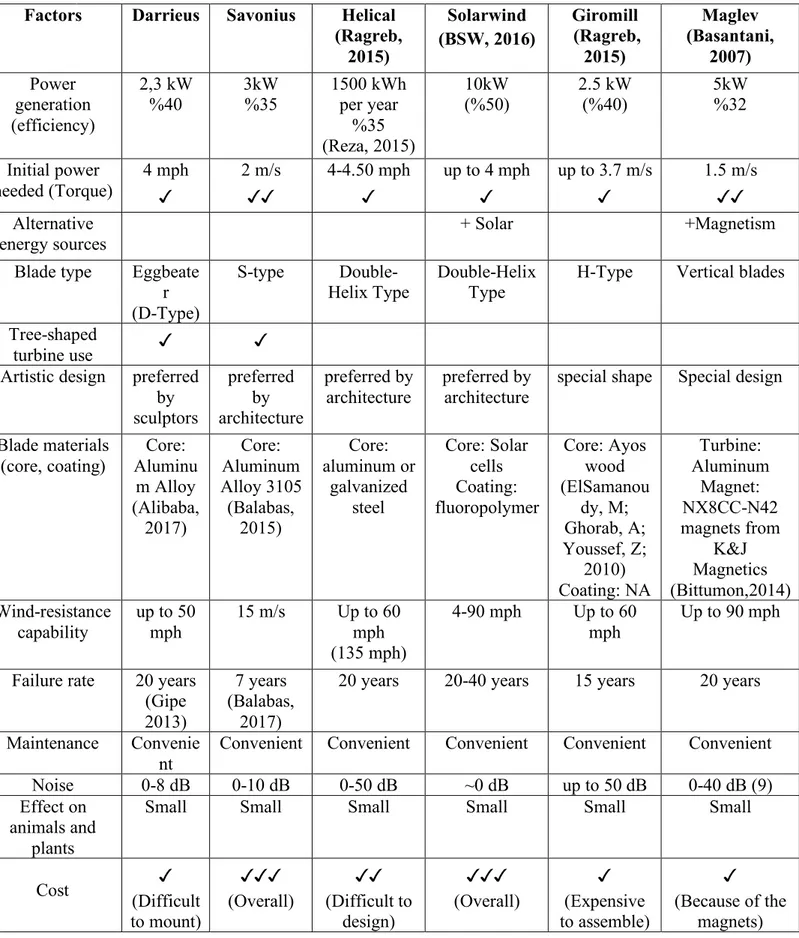
Table 2. Comparison of different types of wind turbines
Factors Darrieus Savonius Helical (Ragreb, 2015) Solarwind (BSW, 2016) Giromill (Ragreb, 2015) Maglev (Basantani, 2007) Power generation (efficiency) 2,3 kW %40 3kW %35 1500 kWh per year %35 (Reza, 2015) 10kW (%50) 2.5 kW (%40) 5kW %32 Initial power needed (Torque) 4 mph ✓ 2 m/s ✓✓ 4-4.50 mph ✓ up to 4 mph ✓ up to 3.7 m/s ✓ 1.5 m/s ✓✓ Alternative
energy sources + Solar +Magnetism
Blade type Eggbeate r (D-Type)
S-type
Double-Helix Type Double-Helix Type H-Type Vertical blades Tree-shaped
turbine use ✓ ✓
Artistic design preferred by sculptors preferred by architecture preferred by
architecture preferred by architecture special shape Special design Blade materials (core, coating) Core: Aluminu m Alloy (Alibaba, 2017) Core: Aluminum Alloy 3105 (Balabas, 2015) Core: aluminum or galvanized steel Core: Solar cells Coating: fluoropolymer Core: Ayos wood (ElSamanou dy, M; Ghorab, A; Youssef, Z; 2010) Coating: NA Turbine: Aluminum Magnet: NX8CC-N42 magnets from K&J Magnetics (Bittumon,2014) Wind-resistance capability up to 50 mph 15 m/s Up to 60 mph (135 mph) 4-90 mph Up to 60 mph Up to 90 mph Failure rate 20 years
(Gipe 2013)
7 years (Balabas,
2017)
20 years 20-40 years 15 years 20 years Maintenance Convenie
nt
Convenient Convenient Convenient Convenient Convenient Noise 0-8 dB 0-10 dB 0-50 dB ~0 dB up to 50 dB 0-40 dB (9) Effect on
animals and plants
Small Small Small Small Small Small
Cost (Difficult ✓ to mount) ✓✓✓ (Overall) ✓✓ (Difficult to design) ✓✓✓ (Overall) ✓ (Expensive to assemble) ✓ (Because of the magnets)
23
From the above information provided, the following conclusions can be made:
● Savonius turbine doesn't require initial impulse, it is easier to produce and is more efficient.
● Engineers tried to combine Darrieus and Savonius as one rotor and they see Darrieus rotor plays greater role for efficiency. When blade amount increases in Darrieus type turbines, their power efficiency increases. Variants of the Darrieus wind turbine are the giromill and cycloturbine. (Liang, Xiaoting 2017)
● Basically, Darrieus rotors cannot start by themselves so purpose is combined Darrieus rotor with Savonius to give it self-start (Liang, Xiaoting 2017).
● The main purpose of combining Darrieus and Savonius rotors is because the turbine can start working at lower operating wind speeds and it produces more energy (higher efficiency). They also rotate at the same time because they are fixed on the same shaft. ● Regarding the Solarwind turbine, uniform energy can be generated throughout the year,
since during winter time there is more wind, but during summer, there is more sun (BSW, 2016)
● It is easy to mount Solarwind turbine because there is a special space in the frame of the turbine that allows the solar cell to be mounted easily.
● Solarwind wind turbines can be also combined in new designs because with solar cells the efficiency increases nearly 50%.
● Tree-shaped wind turbines are designed and constructed to be durable, reliable and lasting in a variety of outdoor conditions. E.g. 26x36-feet tree features 72 leaves. It can work 280 days per year. A common tree-shaped wind turbine produces only 3.1 kW power. Maintenance of about $36.500 for a unit (Pantsios, 2015).
● Giromill wind turbine is very noisy, and blades' materials can be of different types. However, in one case wood is used as blade and it is not environment friendly. It is very difficult and expensive to assemble.
● Maglev stands for ‘Magnetic Levitation’ and they are one of type of vertical axis wind turbines. Their main difference in comparison with the other types of turbines is that instead of using ball bearing they use magnets for spinning. The turbine uses “full-permanent” magnets, not electromagnets, therefore, it does not require electricity to run. (Basantani, 2007)
● The type of magnets used in maglev wind turbine’s is neodymium magnets. It reduces friction loss and maintenance cost. (Basantani, 2007)
● A vertical-axis wind turbine comprises a shaft rotatable about a longitudinal axis and a plurality of blades 10 coupled to the shaft, at least one of the blades having an array of light emitting diodes controlled to generate a viewable image when the turbine rotates about the axis. Preferably means for controlling the LEDs includes variable speed control means to generate a coherent image when the turbine rotates at variable rotational speeds and is part of the turbine. Preferably the turbine generates electricity to power the light emitting diodes. Preferably the LED arrays can be arranged along a
24
leading 17 or trailing 18 edges of a blade 10, or an upper aero foil surface 19 of a blade 10. (Cochrane, 2006)
● Maglev wind turbines use neodymium magnets instead of ball bearings, so those turbines will be more efficient than the other VAWTs, it reduces friction to fair values but also using these magnets lower the maintenance cost instead it requires more budget to produce.
● Combined Darrieus & Savonius type of wind turbines are more efficient than each type of turbines individually, with using Savonius rotor on Darrieus rotor it reduces initial start for Darrieus rotor and it have more efficiency for Savonius rotor.
● Inspiration from Giromill does not makes sense because it is expensive to produce it and also it is not efficient. Besides, it is noisy.
● Ducted type wind turbines work with pressure difference, so if pressure difference is feasible for our design, DAWT can be inspired. with DAWT, there are not any rotor needed.
● The types of plastic filaments for 3D Printing fabrication of blades: There are three main filament types. PLA is a bioplastic filament. It has no bad effect for human health, and even can be used as fertilizer for recycling. The ideal printing temperature of PLA is about 180 and 220 degrees centigrade. The other type is ABS (acrylonitrile butadiene styrene) which is a petroleum-based plastic and has a matt appearance. ABS is very durable and needs a heated bed for printing. The ideal printing temperature of ABS is about 250-260 degrees centigrade. The last type is PVA. For objects that cannot be stayed at air, structures called reinforcements are created during printing. PVA (Polyvinyl Alcohol) is one of the best supporting materials available today with its liquid dissolution property. It dissolves when it is thrown into hot or cold water, helping to free your object from supports. (Kuyucu, 2016)
25
3.2.4.1. Characterization of Savonius Wind Turbines
The Savonius wind turbine is a simple vertical axis device having a shape of half-cylindrical parts attached to the opposite sides of a vertical shaft (for two-bladed arrangement) and operate on the drag force, so it can’t rotate faster than the wind speed. This means that the tip speed ratio is equal to 1 or smaller [4]. As the wind blows into the structure and meets the opposite faced surfaces (one convex and other concave), two different
forces (drag and lift) are exerted on those two surfaces. The basic principle is based on the difference of the drag force between the convex and the concave parts of the rotor blades when they rotate around a vertical shaft. Thus, drag force is the main driving force of the Savonius rotor [5]. Fig.5. (a) shows characteristic parameters of a Savonius wind turbine with two semicircular profile blades.
Figure SEQ Figure \* ARABIC 5. Parameters of
26
4. Turkish Design and Installation Standards/Restrictions of VAWT
4.1. Design Standards and RestrictionsTo build a wind turbine, does not matter the type of axis, there are some design restrictions that should be obeyed. In Turkey, European Norm (EN) Standards are being used. According to TS EN 61400-1, IEC 61400-2 standards, wind turbine structural design shall be based on verification of the structural integrity of the components in the critical load paths from the rotor blades to the foundation. The ultimate and fatigue strength of structural members shall be verified by calculations and/or tests to determine the structural integrity of a small wind turbine with the appropriate safety level.
The structural analysis shall be based on ISO 2394 or equivalent, where applicable.
27
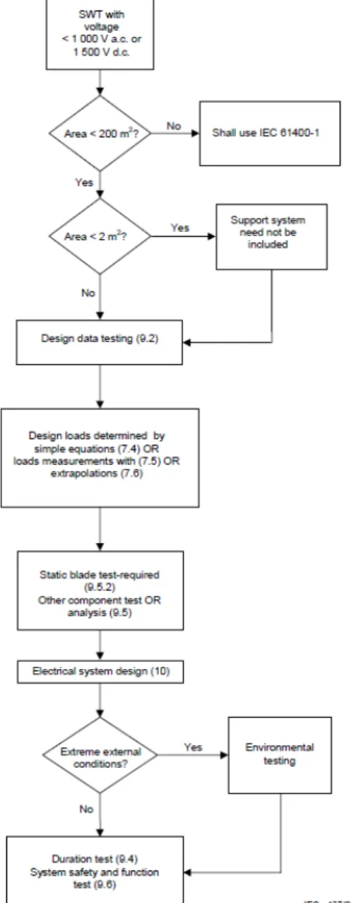
The design method for turbines covered under this part of IEC 61400 is depicted in scheme 1above. A simplified approach is permitted for a variety of turbine configurations. For turbines with a swept rotor area of less than 2 m2, the tower is not considered part of the design.
It should be verified that the limit states are not exceeded for the wind turbine design. There are three ways given to determine the design loads for the turbine:
– simplified load equations;
For certain turbine configurations, the loads can be derived using simple, conservative equations for a limited set of load cases. If the turbine configuration does not meet those configuration requirements, the simple equations cannot be used, instead the alternative aeroelastic modelling or load measurements shall be used. The turbine configurations that can use the simple equations should meet all the following requirements:
● horizontal axis;
● 2 or more bladed propeller-type rotor; ● cantilever blades; and
● rigid hub (not teetering or hinged hub).
The turbine configuration may use an upwind or downwind rotor; it may operate at either variable or constant speed; it may have an active or passive pitch mechanism, as well as fixed pitch; and it may furl about vertical, horizontal, or intermediate axes, as well as not furling. – Aeroelastic Modelling
In case the design loads are determined by aeroelastic modelling. In load cases evaluated where a wind speed range is given, the load case shall be evaluated over the entire wind speed range to ensure the worst load is identified.
– Mechanical Loads Testing
If the design loads are derived from load measurements, these load measurements should be taken under conditions as close as possible to the design load cases described under aeroelastic modelling. Extrapolation of measured loads should occur in compliance with IEC 61400-13. For any of the design load cases in simplified load equations or aeroelastic modelling, load measurements can be used instead of calculations if the measurements were taken under similar conditions as the design load case specifies.
28
Figure 7. Building Procedure
According to Republic of Turkey Ministry of Energy and Natural Sources, anyone can generate energy without taking any license up to 1 megawatt. Scheme 2 above explains the steps of building a wind turbine without taking any license. Republic of Turkey Ministry of Energy and Natural Sources declares that 6.5 m/s of wind is medium, 7.5 m/s is good, and 8.5 m/s is very good velocities due to wind turbines efficiency.
In any case, the ones who want to generate energy less than 1 MW, need to apply distributor company, for MEF University it is Boğaziçi Elektrik Dağıtım A.Ş (BEDAŞ), and ask for the evaluation. After the permission is taken, there will be a letter received that proves the confirmation. After that, ones need to show the confirmation letter to BEDAŞ in 180 days and sign a contract. After all these procedures, power plant building can be started.
The process of the project of wind turbine construction without any license has some procedures, that are; location decision, wind measurements, feasibility report, some confirmation and permissions, transition of the project to the construction phase.
These procedures should be done before building process. To build a power plant that generates less than 1 MW energy, ones (one person or company) must have electricity subscription. Power plant should relate to the grid and more energy can be sold to the government. In the application process, electricity bill, original deed of lease of the place that the wind turbine is built, a document that proves application fee should be paid, averagely 250 liras, a document that shows the single line scheme of the facility.
After the permission is taken, all procedures should be done in 180 days. There are some valuable advices, that are; the land should be as smooth as possible due to its efficiency, the velocity of wind should be averagely 7 m/s, the distance to the transformer should be as short as possible, feasibility report should be taken.
4.3. Dynamic Requirements
Small Wind Turbines support structure resonances can be a critical design issue and as such consideration should be taken to avoid continuous operation at turbine system resonance frequencies leading to excessive vibrations. This is particularly important if the support structure is an occupied building.
29
4.4. Mechanical Component Testing
For all other load carrying components, in the case where no calculations of a component have been performed, that component shall be subjected to a component test. In general, the worst combination of design loads including safety factors shall be applied to the component. No damage that may interfere with the safe operation of the turbine may occur (for example significant loss of stiffness, plastic deformation, buckling or cracking). In case of purchased components, it shall be sufficient to show that the design loads are within the specifications of the component.
-Blade test
The applied load for the static blade test shall be the worst combination of the flap wise bending moment and the centrifugal force. The blade shall be tested including the blade hub connection. No damage may occur at a test load up to the maximum operating load as predicted by modelling or measurements, including safety factors. It is recommended that the blade be tested to failure to determine the strength margin between the design load and actual blade failure load. If a blade fatigue test is performed, the test shall meet the requirements of IEC 61400-23. -Hub test
If a hub test is performed, the hub shall be tested statically by simulating centrifugal force and flap wise bending on all connection points of the blades. The hub shall be tested including the hub shaft connection. No damage may occur at the design test load (including factors of safety) based on the maximum calculated load.
-Nacelle frame test
If a nacelle frame test is performed, the nacelle frame shall be statically tested by subjecting it to a shaft tilt bending moment, axial rotor force and its own weight. No damage may occur at the design test load (including factors of safety) based on the maximum calculated load. -Yaw mechanism test
If a yaw mechanism test is performed, the yaw mechanism shall be tested by applying the loads as described under the nacelle frame test. It shall be shown that the yaw mechanism still works properly.
-Gearbox test
A gearbox test is not required but testing according to the AGMA/AWEA 921-A97 standard is recommended.
-Environmental testing
If the turbine is designed for external conditions outside the normal external conditions, the turbine shall be subjected to tests simulating those conditions. These tests are preferably
30
performed on the whole turbine. If this is not feasible, these tests shall be conducted on all portions of the system that are affected by this external condition.
4.5. Conclusion of Standards
As conclusion, every major component or subsystem in the wind turbine should be evaluated by the certification body as per TS EN 61400-1 and IEC 61400-2. If small power(<1MW) is generated by wind turbine, IEC 61400-2 standard should be obeyed and no need to take license. According to IEC 61400-2;
● Voltage should be smaller than 1000V (ac) or 1500V (dc) ● Area of swept rotor should be less than 200m2
● Design loads should be determined with simplified load equations, aeroelastic modelling or mechanical loads testing.
● Design data, mechanical component, blade, hub, nacelle, yaw testing should be done; also, gearbox testing can be performed but it is not required, and if the turbine is designed for external conditions, environmental testing should be done.
Ones who decide to build a wind turbine should apply to Republic of Turkey Ministry of Energy and Natural Sources to start the building process and need to prove if project is feasible (see scheme 2). After the permission is taken, all procedures should be done in 180 days.
4.6. Airfoil Standards
Airfoils in definition; shape of wing, blade or sail. Airfoils has some specifications like; chamber line, chord line and trailing edge. We considered those specifications during blade selection. There are two types of forces acts on a blade, drag and lift forces. For a regular Savonius types wind turbine blades face with only drag force but if blade has some proper angular positions, also lift forces may occur.
31
There are several standards exist for airfoils such as; NACA, NASA, Onera etc. We picked Goettingen standard for our vertical axis wind turbine, it called Goettingen 448 airfoil. Goettingen 448 airfoil has unique shape and its curve due to its chord line is applicable for our wind turbine. We expected that we can catch wind easily with this curved geometry. After doing some computational fluid dynamics tests, results can be compared with original Goettingen 448 airfoil database. Table 3 below, shows the comparison of airfoils.
Table 3. Airfoil Comparison
GOE
462 GOE 448 E423 (smoothed) CH10 EPPLER 420 GOE 525
Thickness 10.8% 12.9% 12.5% 12.8% 14.3% 16.4%
Camber 13.3% 10.5% 10.0% 10.2% 10.7% 9.7%
Trailing edge angle 4.7° 22.5° 14.1° 13.2° 14.0° 8.6°
Lower flatness 2.8% 6.5% 6.7% 6.4% 6.6% 6.6%
Leading edge radius 3.7% 3.7% 3.2% 2.6% 3.7% 4.8%
Efficiency 50.3 49.9% 48.7 48.4 45.3 52.2 Max CL 2.381 2.357 2.357 2.27 2.477 2.712 Max CL angle 15.0 13.5 14.5 11.5 15.0 15.0 Max L/D 596.019 55.149 67.65 69.198 82.799 83.087 Max L/D angle 0.0 3.0 -1.0 -0.5 -0.5 -0.5 Max L/D CL 1.264 1.464 1.212 1.354 1.337 1.467 Stall angle 0.0 -0.5 14.5 -0.5 -0.375 -4.0
Zero lift angle -10.5 -10.5 -10.5 -11.5 -11.0 -12.0
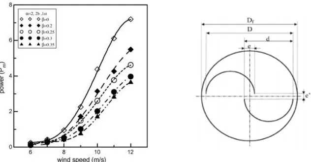
4.7. Overlap Study
The ordinary Savonius rotor has pairs of cylindrical blades and they are not connected to the middle or with gaps (overlapping) on both ends.
Various overlap ratios from 0 to 0.35 are studied experimentally at constant values of the other studied parameters. Figure illustrates the relation between mechanical power and wind speed
32
for the tested overlap ratios. It can be noticed here that the rotor with overlap gives higher mechanical power than rotors without overlap.
Figure 9. Effects of Different Overlap Ratios & Ratio Formula Representation With different overlap ratios from 0 to 0.35 are investigated experimentally to determine the optimum geometries of Savonius turbine. The rotors without overlap ratios are better in operation than those with overlap. (Mahmoud, 2010) (Lednicer,2010) (Yaakob, 2009) (GOE 462, 2018)
Concludes; The best results for overlap ratio is around β = 0.21 for Savonius turbines β can be represented as; β = e/d. They also mentioned best power coefficient values observed in between 0.20 -0.25. We can justify those values from figure that represents their experiment. (Zhu, 2014)
33
For this article they mentioned, overlap ratio is an advantage and they observed best overlap ratio is 0.5 and corresponding to the max. power coefficient is 0.261. (Akwa,2012)
The buckets overlap of the rotor indicates that the maximum device performance occurs for buckets overlap ratios with values close to 0.15. Overlap ratio for Savonius wind turbines information is obtained from CFD. Also, rotor operation is more efficiently at 1.25 tip speed ratio. As a result, the best performance gives an averaged power coefficient is 0.3161.
The comparison of overlap ratios with respect to Literatures Name of article Which ratio is better Mahmoud, 2010 Overlap ratio has bad effect
Lednicer, 2010 0.15
Yaakob, 2009 0.21
Zhu, 2014 0.5
Akwa, 2011 0.15
5. MODELLING, ANALYSIS, TESTING AND OPTIMIZATION
5.1. Design SpecificationsThe tentative vertical wind turbine design should consider two or three blades for a Savonius/Helical type; however, further optimization may decide the improved number of blades. It should produce between 0,5 and 2 kW energy, to be able to charge three to four mobile phones simultaneously. Tentatively, solar panels should be mounted on the shell of the blades and/or assembled to an efficient position and location. As a core material, PLA filament is recommended to be used, and the blades may be fabricated by 3D printing. By using PLA filament there will no need to apply coating material on the turbines, however, some waterproof coating might be applied. Clean-room technology will be used during the design process to cover the bearings and rotating parts. The blade size will be decided after CAD and computational fluid designs tests. Generators shafts can be used instead of ball bearings to eliminate turbine noise and increase its efficiency. The “Tribine” is going to be manufactured in an artistic fashion, considering environment friendliness and sustainability. More details are given in the table 3 below in optimization section. The other trouble is blade type. To manufacture blade, the trailing edge angle should be large as possible. Also, the efficiency of turbine is another parameter. The efficiency should be as high as possible.
5.2. Motor Selection
Major types of rotational electrical machines commonly used in a wind power generating systems are:
1.The direct current (DC) machine, also known as a Dynamo
2. The alternating current (AC) synchronous machine, also known as an AC Generator
34
3. The alternating current (AC) induction machine, also known as an Alternator. All these electrical machines are electromechanical devices that work on Faraday’s law of electromagnetic induction. That is, they operate through the interaction of a magnetic flux and an electric current, or flow of charge. As this process is reversible, the same machine can be used as a conventional electrical motor for converting the electrical power into mechanical power, or as a generator converting the mechanical power back into the electrical power.
Figure 11. Wind Turbine Induction Generator
The electrical machine most commonly used for wind turbines applications are those acting as generators, with synchronous generators and induction generators (as shown) being commonly used in larger wind turbine generators, while smaller and homemade wind turbines tend to use a low speed DC generator or Dynamo as they are small, cheap and a lot easier to connect up. So, it makes a difference what type of electrical generator we can use to produce wind power. The simple answer is both Yes and No, as it all depends upon the type of system and application you want. The low voltage DC output from a generator or older style dynamo can be used to charge batteries while the higher AC sinusoidal output from an alternator can be connected directly to the local grid.
Also, the output voltage and power demand depend entirely upon the appliances you have and how you wish to use them. In addition, the location of the wind turbine generator, would the wind resource keep it constantly rotating for long periods of time or would the generator speed and therefore its output vary up and down with variations in the available wind.
There are two ways to produce direct current. Either AC or DC motors can be used. Motor should be without redactor to eliminate noise. (alternative-energy-tutorials.com, 2017)
35
Qualifications AC Induction Brushless DC (BLDC)
Traditional DC
The speed/torque characteristics
Nonlinear. It enables lower torque at lower speeds.
Poor torque control.
Flat in nature. It enables operations at all speeds with rated load.
Controllable torque.
Flat in nature. It enables operations at all speeds with rated load.
Controllable torque.
Output power
Output power/frame size is moderate. Because both stator and rotor have windings, output power to size is lower than BLDC.
Output power/frame size is high. Because it has permanent magnets on the rotor, the smaller size can be achieved for a given output power.
Output power/frame size is high. Because it has permanent magnets on the rotor, the smaller size can be achieved for a given output power.
Size/Weight ratio 100% 70% of AC @ 1HP
55% of AC @ 2HP
Lighter than AC motor. (i-glamour, 2014)
Efficiency 40-45% 70-75% The efficiency of DC
motors is about 10 to 20% larger than AC motors
Reliability High (no brushes) High (no brushes) Low (because of carbon-brush wear)
The rotor inertia High. This enables poorer dynamic characteristics.
Low. This enables better dynamic characteristics.
Medium
The starting current
Approximately up to 7 times of rated. Stator circuit rating should be carefully selected. It normally uses a star delta starter.
Rated. No special starter circuits are required.
No special requirements
Controller /Driver Requirement
Difficult & nonlinear speed control. Required for fixed speed. A controller is required only if variable speed is desired.
Easy & linear speed variable control. Always required to keep the motor running.
Easy & linear speed variable control if required.
Rotor Frequency
The rotor runs at a lower frequency than the stator by slip frequency and slip
No slip experienced between stator and rotor frequencies.
36 increases with load
on the motor.
Accuracy of speed 3-5% 0.5% 0.5%
Cost
Cheaper for middle sizes.
Cheaper for smaller sizes.
Cheaper for smaller sizes.
Raw material cost AC <= BLDC driven by size/weight Lower than BLDC and AC for our case.
5.2.1. Differences between traditional DC vs AC motors
● AC motors are used for small scale applications where the output is between 1 to 100 Watts. DC motors are used for bigger applications and to get a greater power output. ● The structure of an AC motor is simple, but the structure of a DC motor is more
complicated.
● AC motors do not have to be checked for maintenance regularly and have greater stability, but DC motors must be maintained properly because of the presence of a commutator and are less stable.
● AC motors have a more complicated control structure while DC motors can be monitored easily.
● AC motors are more expensive but have a structure which is lighter, better and efficient. DC motors are cheaper but are heavier in comparison and are larger in size.
37
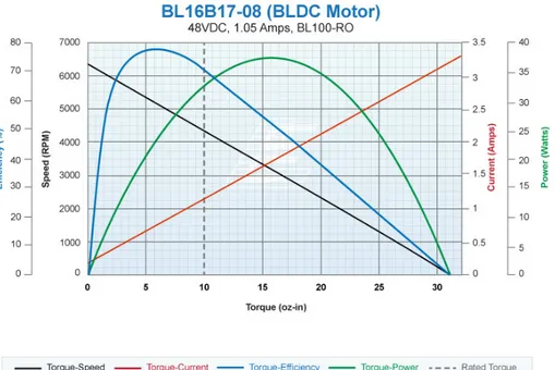
5.2.2. AC, DC & BLDC Motor Characteristics
Figure 12. DC & AC Characteristics
Figure 13. BLDC Characteristic
38
As conclusion of t is better to use DC motors because no converter is needed, and its cost is much less (about 25 times).
● As less as possible rpm is needed.
○ Rpm value can be calculated with; !"#
$% 𝑉'
○ Where Vn is voltage of motor and Vb is battery’s voltage.
● Most possible efficiency should be produced with low rpm formula; ○ Poutput / Pinput x 100%
The example below describes the efficiency when Zener Motor is chosen.
○ (4000/220) x 24 = 436 rpm effective (436/4000) x 100 = %10,9 efficient ● As compact as possible.
● Brushless motors require driver and it affects cost.
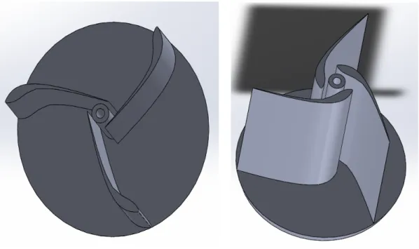
5.3. Computer-aided Design Modelling
In this section, you can see CAD models of first samples. For 3D printing this design process must be done flawlessly. First, we created for two blade drawings then started to make a 3-blade design of 3-blades. Pictures can be found below.
39
Figure 15. GOE 448 Three Blade New CAD Models
Figure 16. Two Different options for open shaft GOE 462 Airfoil
In this figure, you can see the two different options for direction of blade. The first one is increased moment of inertia so; second model is preferred but it is not feasible for manufacturing it with 3D printer, so we decided to stick with GOE 448 three bladed models.
40
5.4. Simulation
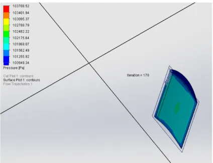
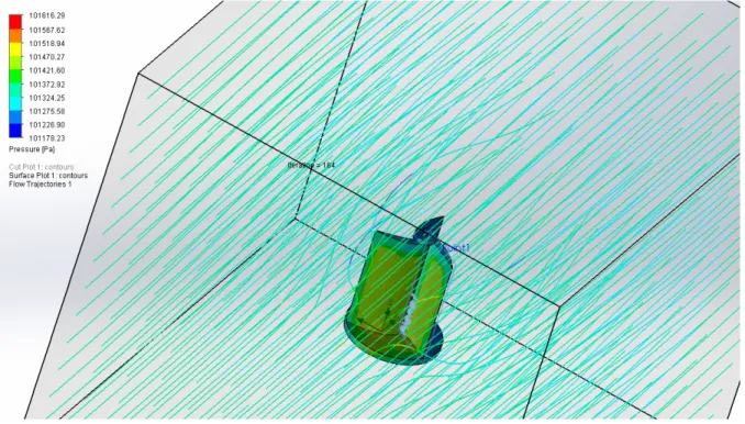
For the flow simulation part, Solidworks flow simulation add in preferred to use, initially we wanted to check feasibility of the flow simulation on Solidworks, due to that reason we test flow simulation on one fixed blade, can be seen on Figure 17. The results were satisfying, we can able to see/obtain pressure distributions, flow trajectories, force, shear stress, velocity at any direction etc. Also, for finding responses, frequencies and mode shapes we used Solidworks regular simulation feature. We applied different flow simulations to find what is the maximum force with changing angle of attack on blades. All results and figures can be found below.
5.4.1. Fixed Blade Feasibility Test
First, we wanted to try SolidWorks flow simulation feature before we start simulations on real three bladed prototype we wanted to test flow simulation feature with one fixed GOE 448 blade. Results were satisfactory, and we can able to see flow trajectories, pressure distributions and any surface goal that we inserted at the beginning of the flow simulation.
41
Figure 18. Flow Trajectories on a Single Blade
5.4.2. Tests on Three Bladed Turbine
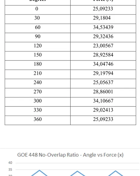
After the feasibility test of Solidworks Flow Simulation feature is tested on a single GOE 448 blade, we decided to advance on three blade models. In this case angle of attack is changing every 30 degrees and we applied several surface goals to compute required values for the calculations. Wind direction as taken as X direction and 15m/s.
42
Table 5. Results of The GOE 448 No Overlap Ratio with Different Angles
Degrees Force (N) 0 25,09233 30 29,1804 60 34,53439 90 29,32436 120 23,00567 150 28,92584 180 34,04746 210 29,19794 240 25,05637 270 28,86001 300 34,10667 330 29,02413 360 25,09233
43
Table 6. Results of The GOE 448 With Overlap Ratio with Different Angles
Degrees Force (N) 0 24.50689 30 29.32720 60 33.85062 90 29.32436 120 25.09233 150 28.56480 180 34.37590 210 29.02266 240 24.90568 270 28.90568 300 33.56672 330 29.12356 360 24.50689
Figure 21. GOE 448 With Overlap Ratio Angles vs Forces
When we wanted to compare overlap, ratio is logical to use parameter or not, we created also a model with overlap ratio and simulated it, but results were very close to each other. If you check the figure above the pattern can be seen on the figure, every 120 degrees it must give same force values due to three blade geometries and they are nearly the same. As a result, this analysis data shows that we cannot conclude which one is better than the other because of the simulation type.
44
5.4.3. Frequency Simulations
Every structures or machine elements have natural frequency, when we are applying dynamic analysis to find natural frequency we are also finding that component’s different mode shapes. Every mode vibration characterized by a frequency and mode shape. Mod shapes are basically, system’s response due to applied conditions. For example, in mod shape 2 we obtained torsion at this mod shape but when we check mod shape 2, we can see there is bending and also torsion little bit. It is very dangerous to reach any structure or component’s natural frequency, it will take serious and permanent damages or even can be destroyed by vibrations. The Mode shape and natural frequency responses can be seen below.
45
Figure 21. Frequency Simulation Results for Different Mode Shapes
In frequency table we can see how frequency changes with different mode shapes, all those different mode shapes represent different deformations. First mode shape is representing natural frequency.
Table 7. Frequency Responses
Mode Shape 1 8,5451e-005 Hz (Wn)
Mode Shape 2 95,655 Hz
Mode Shape 3 104,39 Hz
Mode Shape 4 104,64 Hz
5.4.4. Conclusion of Simulations
So far usage of flow simulation & simulation features in Solidworks were new for us and this was great opportunity to learning and discovering it. After all we have to test this simulation feature and as a group decided to apply a simulation on one sample blade. The results were meaningful, and we can see pressure distributions, flow trajectories and our assigned surface goals on the blade. Then created three bladed GOE 448 turbine and started to apply same procedure on this model. Investigated three bladed GOE 448 no-overlap model had a good
46
pattern as a result with changing angles. For the comparison also, we created a model with 0.25 overlap ratio. 0.25 selected due to several sources and feasibility of our design parameters. As a result of this model’s simulation was not good and plot was distorted. After those results we decided to move on with no overlap model. Lastly frequency simulation has done on this model for obtaining mode shapes and its natural frequency.
5.5. Cost Analysis
For the cost analysis we mainly we must consider; Electrical components such as motors, redactors, batteries etc., printing material and mechanical components such as; bearings, shaft & base etc. From now on we only dealt with design part and benchmarking of motors & batteries, we did not buy any components for this semester. For printing material and printer, we used our sources from MEF University mechanical engineering laboratory. You can see benchmarking search for batteries and motors below.
Table 8. Comparison of Motors
Motor Type Power
(W) Speed (rpm) Voltage (V) Price (TL)
Wellington Motor (BLDC) ≈ 100 1500 220 150 (Without Driver) Excem Motor (BLDC) ≈ 100 3000 24 1000 (including driver) Mogus Electronics(DC) ≈ 100 2800 24 190 Zenger Electronics(DC) ≈ 100 4000 230 40 Keskinler Motor1 (DC) ≈ 100 2500 230 75 Keskinler Motor2 (DC) ≈ 100 10000 220 35 Mitsumi (DC) ≈ 100 4000 21 40
47
Table 9. Comparison of Batteries
Battery Selection Voltage (V) Ampere (A) Price (TL)
Zenger Electronics 1 6 1,3 14
Zenger Electronics 2 6 4 20
Zenger Electronics 3 12 1,3 22
Zenger Electronics 4 12 2,6 25
Car Battery 12 60-72 250-600
Table 10. Economic Comparison of DC Motors
Motor types and economic quantities BLDC motor DC motor
Price per motor (TL)
300
60
Lifetime for a motor (year)
10
1
For ten years needed number of motor
1
10
Total cost for ten years(TL)
300
600
Table 8 shows us; the BLDC motor has lower cost than DC motor two times. Table 9 below, shows the cost calculations in detailed.
Table 11. Detailed Cost Calculation
Product Price (TL)
PLA filament (10 kg) 1200 12V 2.6A DC Motor (2) 300
Batteries (4) 100
Others 400
Charge Controller 300 (gittigidiyor,2018)
48
The average cost of the project is around 2000 Turkish Liras. PLA filament has already decided to use. Since four different prototypes are going to be manufactured, averagely 10 kg of filament will be needed. Two prototypes are going to be tested in the same time, for this reason, two DC motors are needed. Price is taken according to the market research that is done in the previous semester. 24 V of battery is needed, so two 12V batteries need to be connected, so in total four-12V batteries are needed.
Others stand for the other components for the design, such as shaft, bearings, electrical layout components etc.
5.6. Testing
In this section you can found different experiments that we made during project. In first experiment a hair dryer to simulate/produce wind power, also tachometer to measure how much time rpm can we catch for each paper prototype. You can see results and photos below.
49
Table 12. Experiment conducted to test the efficiency of the number of blades
Blade Type RPM Power-to-Weight
Ratio(rpm/kg) 3 Blade 770 ± 20% 128 2 Blade 630 ± 22% 105 DNA 718 ± 17% 103 Power= 1800W Voltage= 220V Frequency=50-60 Hz
Distance between blower and wind turbine 450mm
As a conclusion, the experiment is made with using three different paper wind turbines, such as 3 blades, 2 blades and DNA type, measured with the tachometer to define rpm values. Experiment is done with several times to find average rpm values for each wind turbine. When power-to-weight ratio was calculated, torque of the wind blower is not considered because it’s eliminated in the end of the process. The experiment proves that using 3-blade wind turbine is the most efficient and reasonable option for turbine selection.
5.6.1. Test on Printed Three Bladed Models
In this section you can found two different tests. One of them is for model which has overlap ratio and other one has no-overlap ratio. In this experiment we used air blower for generating wind which is 1400 W & 30000 rpm, a non-contact tachometer for measuring rpm of the blades and two different blade models for comparison. The results can be seen below.
50
Table 13. Test on Printed Three Bladed Test Results
Trials
No-overlap ratio angular velocity (rpm)
With overlap ratio angular velocity (rpm) 1 761 878.4 2 805.7 870 3 778.8 885 4 743.2 862 5 706.3 897.9 6 748.5 851.4 7 737.6 852.5 8 775.5 851 9 799.9 864.8 10 812.9 876 11 795.8 880.6 12 785.6 867.1 Average 770.9 869.7
51
Figure 22. Air Blower Location & Setup
As a conclusion, initially with flow simulation we could not decide which model is efficient, model with overlap ratio or no-overlap ratio. Flow simulations were not dynamic simulation and it was hard to compare results. After that we decided to prepare second experiment to decide which model is better. According to the results and after several trials we took average values of the results and we decided to continue model with overlap ratio.
5.6.2. Tips for 3D Printing & Analysis
● Product of inertia must be considered, and computational fluid analysis must be done before printing.
● To avoid thermal stress of the printing material, drawn parts must be applicable for scaling, for this case in figure 10 we did not consider scaling for shaft, it was too small, and it did not print well due to thermal stress, inner shaft was distorted.
● Shaft diameter of the blade will change with the proper material selection, these criteria will be discussed later.
● According to the test of paper models, the best selection will be 3 blades or DNA type but DNA type of blades hard to draw on CAD programs.
52
Figure 24. First Printed Prototype
5.7. Optimization
Table 14. Design Requirements and Tasks DESIGN
CRITERIA DESIGN REQUIREMENTS AND TASKS
Power generation (efficiency)
In the range of 1 kW to 3.5 kW (charging smartphones, and electronic devices)
Initial power needed (Torque)
Combination of Savonius + Helical + solar panel blades + ducted type (tentatively). The number and shape of the blades should be optimized to produce more energy
Alternative
energy sources From solar panels Blade type S-Type + Helical
Tree-shaped turbine use
Solar panels should cover most-exposed-to-sun blade sides, and other tree parts. The three should withstand significant wind turbulences.